Coriolis Mass Flow Meter Technology
Coriolis Mass Flow Meter — Working Principle, Installation & Price.
A Coriolis mass flow meter reads the Coriolis effect to measure mass flow directly — the same physics a fuel depot uses to prove a tanker’s load or a chemical plant uses to close a batch. Output is mass, density, and volume in one 4-20 mA loop, with no pressure or temperature compensation needed.
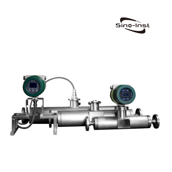
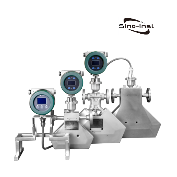
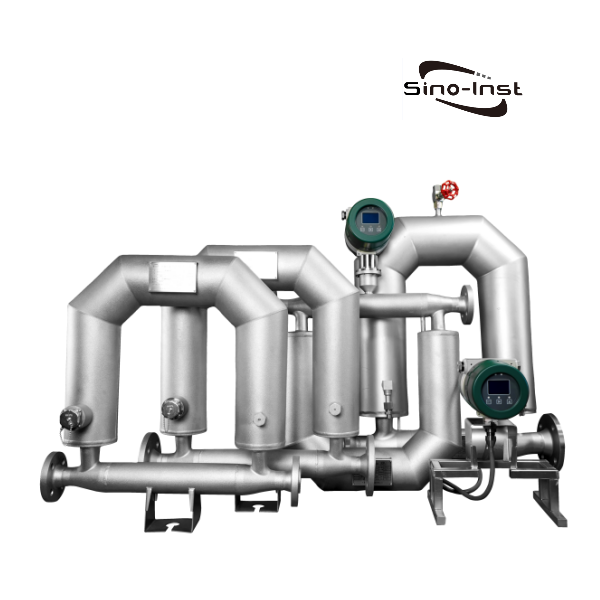
The Coriolis mass flow meter (also called a micro motion flow meter) is built around a vibrating U-tube, straight-tube, or twin-tube sensor. Fluid flowing through the tube deflects it by microradians; that deflection is proportional to mass flow. Because the measurement is physical — not inferred from pressure or velocity — Coriolis meters are the default for custody transfer of hydrocarbons, LPG, and industrial gas, and for process control where density or concentration has to be tracked in real time. The tradeoff: a Coriolis meter costs more than a DP or gear meter, and does not tolerate two-phase flow as well.

Featured Coriolis Mass Flow Meters
What is a Coriolis Mass Flow Meter?
A Coriolis mass flow meter measures mass flow directly by reading the Coriolis effect in a vibrating tube. Unlike a DP, turbine, or vortex meter that gives you volume — which has to be compensated for temperature and pressure before you can bill it — a Coriolis meter reports mass, density, and volume from the same tube. No density transmitter, no second loop, no math in the PLC.
Coriolis is the technology of choice whenever fluid properties change, density matters, or the number on the ticket has to be provable — custody transfer of hydrocarbons, chemical batching, food & beverage blending, pharmaceutical dosing.
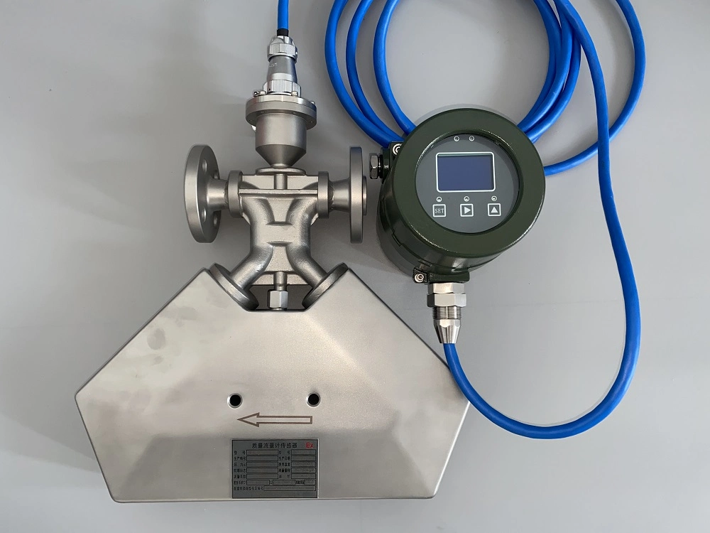
A Coriolis mass flow meter (sometimes called a Coriolis force meter or micro motion meter) has two parts: a sensor — one or two tubes vibrating at their natural frequency — and a transmitter. Fluid moving through the vibrating tube generates a Coriolis force that twists the tube. The twist is measured as a phase shift between two pickoffs on either side of the tube. That phase shift is directly proportional to the mass flow rate. Resonant frequency shifts tell you density. From mass and density you get volume, concentration, and Brix on the same loop.


A Coriolis meter is a direct mass flow meter — the tube twist is the measurement. The industry uses three broad approaches for measuring mass flow, and only one reads mass straight from the physics:
- Direct mass flow meter — one sensor reads a quantity proportional to mass flow. Coriolis sits here. The tube twists under the Coriolis force, the transmitter reads the twist, and that number is the mass flow.
- Derivative mass flow meter — a volume flow meter plus a separate density meter. A computer multiplies the two. Accuracy is the sum of two instrument errors, and you now own two devices to calibrate.
- Compensated mass flow meter — a volume flow meter plus temperature and pressure transmitters. Density is inferred from a state equation. Fine for steam or cleaned-up natural gas, not for fluids whose composition drifts.
Working Principle of Coriolis Mass Flow Meter
A Coriolis mass flow meter measures mass flow directly by reading the Coriolis force generated inside a vibrating tube. The sensor tube — U-shape, Omega, straight, twin-bent, or triple-spiral depending on the model — is driven at its natural frequency by a small coil. When fluid flows through the oscillating tube, it resists the rotation on the inlet half and pushes with it on the outlet half. The result is a twist the transmitter picks up as a phase shift. Phase shift out, mass flow in.
The intuition — a merry-go-round and a garden hose
- The Coriolis force is the sideways force you feel whenever mass moves toward or away from an axis of rotation.
- Ride a merry-go-round and walk toward the center: you have to lean the direction of rotation, because your body wants to keep the tangential speed it had further out.
- Run water through a flexible hose and swing the hose side-to-side in front of you: the hose twists. The moving water resists the swing on one half and adds to it on the other.
- A Coriolis meter does exactly that, at high frequency and low amplitude. A coil vibrates the sensor tube a few microns at its natural frequency.
- Fluid moving through the vibrating tube twists it. The twist is directly proportional to the mass flow rate — no density assumption, no state equation.
- Two pickoffs on either side of the tube measure the phase shift between the inlet and outlet halves. The transmitter converts that phase shift into a 4-20 mA signal, a pulse, or digital output.
The math — from Newton to mass flow
Every Coriolis mass flow meter is a pair: a sensor (the tube and pickoff coils) and a transmitter (the electronics that drive, digitise, and output the signal). The sensor carries the mechanical work; the transmitter carries the math.
The physics sits on Newton’s second law — F = m·a. Rewrite it as m = F / a and you have the measurement: force out of the tube divided by the acceleration the transmitter imposes on it gives mass.
When a fluid particle of mass m moves at velocity v through a tube rotating at angular velocity ω, the particle feels two acceleration components from the tube:
(1) Normal (centripetal) acceleration αr: magnitude ω²r, pointing towards the axis of rotation.
(2) Tangential (Coriolis) acceleration αt: magnitude 2ωv, perpendicular to both v and ω. This is the component that twists the tube.
The tube reacts to that tangential acceleration with an equal and opposite Coriolis force, Fc = 2·m·ω·v. Rearranged for what we measure:
qm = Fc / (2·ω·L) — where qm is the mass flow rate and L is the effective length of the tube. Angular velocity ω is a known constant set by the driver coil. Fc is what the pickoff coils read as phase shift between inlet and outlet. That is the Coriolis mass flow meter principle in one equation.
The same tube also reports fluid density: denser fluid loads the tube, drops its resonant frequency, and the transmitter reads density off that frequency shift. One sensor, two measurements — that is why a single Coriolis meter can replace a separate density meter on most skids. When density or concentration itself is the primary measurement, a dedicated Coriolis density meter is built for exactly that job.
Advantages and Disadvantages of Coriolis Flow Meter
| Advantages and Disadvantages of Coriolis Flow Meter | |
| Advantages | Disadvantages |
| Can handle sanitary applications | The cost is high, especially for line sizes above four inches. |
| Approved for custody transfer and is highly reliable and low maintenance | |
Universal measuring principle for liquids and gases | Poor zero stability which affects the flow meter accuracy. |
Multivariable measurement – simultaneous measuring of mass flow, density, temperature and viscosity | |
High measuring accuracy: typically ±0.1% o.r., optionally: ±0.05% o.r. (PremiumCal) | It cannot be used to measure fluids with lower density, such as low pressure or low density gas. |
Measuring principle independent of the physical fluid properties and the flow profile | |
No inlet/outlet runs necessary. Generally, it is not required straight pipe lines when installing the sensor. | Slightly higher gas content in the liquid may cause a significant increase in measurement error. |
It has a wide range of measurable fluids. Including high viscosity fluids, liquid-solid two-phase fluids, liquid-gas two-phase fluids containing trace gases. And medium and high pressure gases of sufficient density. | |
The change in fluid viscosity has no significant effect on the measured value. | It is sensitive to external vibration interference. |
The change in fluid density has little effect on the measured value. | |
Bidirectional flow measurement | It cannot be used for larger diameters. Currently max size we can make is 8 inch Coriolis flow meter. |
It can take measurement of high viscosity fluids, such as crude oil, heavy oil, residual oil and other liquids with higher viscosity. | |
Pressure drop can be a consideration for “U” shaped tube designs and high viscosity fluids. | The pressure loss is large, especially when measuring a liquid with a high saturated vapor pressure. The pressure loss may cause vaporization of the liquid, and cavitation occurs. |
Coriolis vs Thermal Mass Flow Meter
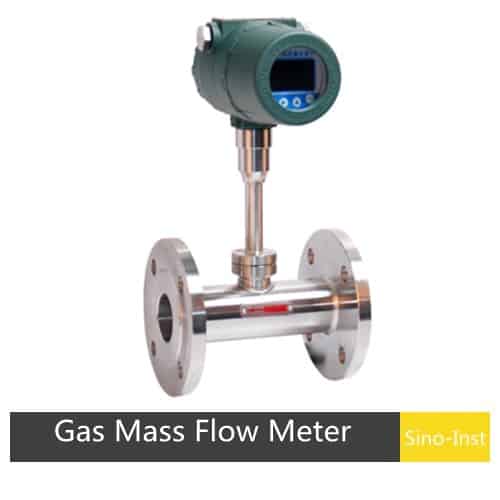
A thermal mass flow meter reads mass by heat transfer — it heats a sensor in the flow stream and measures how much energy the fluid carries away. Thermal is cheap and works well on clean, dry gas at low flow, but a change in humidity, gas blend, or composition throws the reading off. A Coriolis meter measures physical deflection, so the same meter keeps reading correctly when the fluid changes. Where that matters:
- Fluid-independent — no recalibration when the feedstock or gas blend changes
- Gas or liquid, same sensor — no separate meter for each phase
- Handles undefined or variable mixtures (mixed hydrocarbons, slurries)
- Works on supercritical fluids: CO2, ethylene, LNG vapour
- Same footprint as a standard spool — DN15 to DN200 coverage from one body style
- Accuracy: ±0.1–0.2% of rate for liquids, ±0.35–0.5% for gases
- Turndown up to 1:200 on a single sensor (some models 1:2000)
- Response time 50–100 ms — fast enough for batch-end cutoff valves
Coriolis also handles supercritical CO₂ and ethylene, fluids where the phase line is too blurry for thermal meters to resolve. For food & beverage lines running brix or sugar, Coriolis gives density and mass in one instrument — thermal gives neither.
Applications
A Coriolis meter earns its price in fluids that are expensive, reactive, or legally measured. Typical use:
- Food & beverage — sugar, brix, yeast slurry, dairy
- Pulp & paper — black liquor, fibre slurries
- Petrochemical — feedstock dosing, polymer batching
- Oil & gas — custody transfer of crude, LPG, natural gas liquids
- Power — fuel oil, hydrogen coolant
- High viscosity — polymer, heavy residue, asphalt
- Paint & coatings — batch dosing with density check
- Mining — tailings and concentrate pumping
- Process control — chemical injection, reactor feed
- Water & wastewater — chemical dosing and sludge
- Anywhere density matters as much as flow
Installation, Operation & Maintenance
Before we get into mounting and wiring, three operating caveats that apply to every Coriolis meter in service:
• Run the meter in the upper part of its flow range. Sizing a Coriolis meter for “one day we might double the flow” costs you accuracy every day you run at 10% of full scale.
• High-viscosity fluids raise the pressure drop across the sensor. Size the meter against your thickest-operating viscosity, not the datasheet water figure.
• For liquid service, keep the tube 100% full; for gas service, respect the lower flow-range limit and expect a measurable pressure drop. For any service, isolate the sensor from pipe vibration.

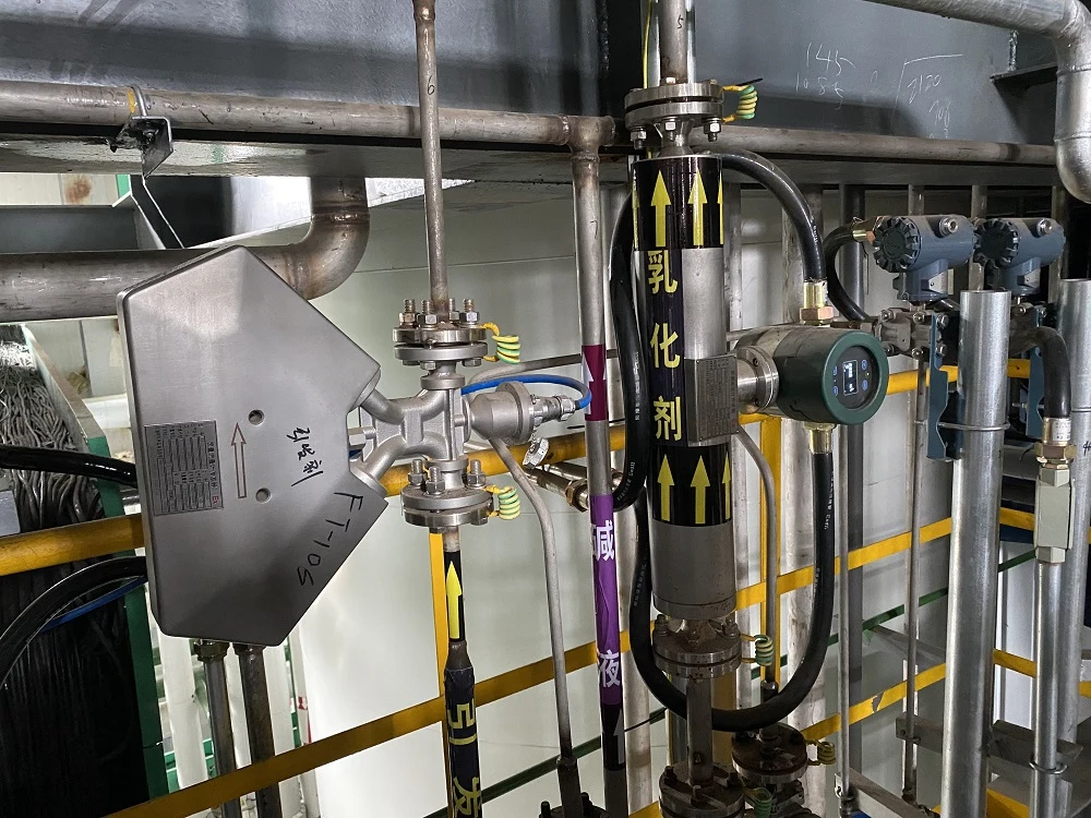
A Coriolis meter is unforgiving of bad installation. Get the mounting, piping, and wiring right the first time and the meter runs for ten years; get them wrong and you will chase drift, zero shift, and “the meter is lying” tickets for the life of the asset.
Mechanical installation — what to get right:
a. Mount the sensor on solid ground. Small-bore meters (ID < 10 mm) belong on a flat, rigid surface — wall, floor, or skid frame — with the sensor isolated from line vibration by flexible couplings at inlet and outlet. Large-bore meters install directly on the process pipe, but the pipe itself must be clamped and supported so the meter does not act as a pipe hanger.
b. Avoid meter-to-meter crosstalk. When two Coriolis meters sit on the same pipe run, they can couple through pipe vibration. Keep at least 10·DN between sensors, or order matched drive frequencies.
c. Keep the tube full. On a liquid line, install the sensor in a low loop or vertical-up flow orientation so the tube never drains. An air pocket in one tube leg produces a false zero and a failed calibration.
d. Respect the flow direction. Most sensors are bi-directional in firmware, but the arrow on the housing is the calibrated direction — install it that way and flag any reversals in the DCS.
e. Ground the transmitter and the sensor. The Coriolis signal is a small phase shift riding on a high-frequency drive signal; a bad earth connection puts noise straight onto the mass-flow output.
Use and maintenance — what to do and when:
① Zero the meter after start-up. Fill the sensor with process fluid, close the downstream block valve, wait for temperature to settle, and run the zero routine. Skipping this is the single most common cause of custody-transfer disputes.
② Re-zero after major process changes. Fluid change, seasonal temperature swing, new pump, new orifice plate downstream — any of these can shift the zero. Plan a zero-check into the PM schedule.
③ Inspect the transmitter display and diagnostics monthly. Modern Coriolis transmitters report drive gain, tube frequency, and pickoff amplitude. A drive gain climbing towards 100% means the tube is fouling or gas is entrained.
④ Do not re-calibrate in the field unless the manufacturer signs off. Coriolis factory calibration is water-traceable and stable for years; a poorly-executed field cal is worse than no cal.
⑤ Keep the external surface clean and dry. Electronics housings are rated for ingress, but standing water, process leaks, and insulation condensation eat at terminals over time.
How Does a Coriolis Meter Measure Density?
Mass flow is read from the phase shift between the two pickoff coils — the heavier the flow, the more the tube twists. Density is read from the tube’s natural frequency — the denser the fluid, the more mass loads the tube and the lower the frequency. Once density is known, the transmitter divides mass flow by density to give you volumetric flow. One sensor, three measurements: mass, density, and volume.
In the flow measurement industry, “direct mass measurement” is a selling point because most of the alternatives — orifice, turbine, Coriolis-free vortex — measure volume and then correct for temperature, pressure, and density. A Coriolis mass flow meter skips the correction step. That is why custody-transfer codes (API MPMS Ch. 5.6, ISO 10790) list Coriolis as a preferred technology for hydrocarbon liquid mass billing.
Density from the same sensor. The tube’s vibration frequency is inversely proportional to the square root of fluid density (f ∝ 1/√ρ). Measure the frequency shift and you know the density. That is why every serious Coriolis transmitter also reports density, °API, and concentration without any added hardware.
Mass flow, density, and volumetric flow — one meter, one 4-20 mA loop (plus HART or Modbus for the rest). That is the reason a Coriolis meter costs more and earns its keep.
Difference between mass flow meters and volume flow meters
A volume flow meter tells you how much fluid went by in cubic units. A mass flow meter tells you how much actual matter went by. For a liquid at steady temperature the two are almost the same; for a gas, or a liquid whose density drifts, they are not. Coriolis sits in the mass-flow camp and reads mass directly — no pressure or temperature compensation, no state equation.
A simple picture. Take a 1-litre cylinder with a frictionless piston. Fill it with air at 1 bar and 0 °C — 1.293 g of air. Push the piston halfway down: the volume is now half a litre and the pressure is near 2 bar, but the mass is still 1.293 g. Nothing was added or removed. Volume and pressure moved; mass did not. That is the whole reason mass flow and volume flow give different answers.
In principle, mass flow should be reported in units of weight — g/h, kg/h, mg/s. In practice, plant operators live in volume units, so the industry reports mass flow in volume units corrected to a fixed reference temperature and pressure. That is what “normal” and “standard” conditions are for, and that is where two engineers can disagree by 7 % without either of them being wrong.
“Normal” conditions (European / IUPAC): 0 °C and 1.013 bar. Units carry an “n” — mln/min, m³n/h.
“Standard” conditions (European): 20 °C and 1.013 bar. Units carry an “s” — mls/min, m³s/h. “Standard” conditions (American): 0 °C (32 °F) and 101.325 kPa absolute (14.6959 psia), used in sccm, slm, and scfh.
Same word, different numbers. Before you accept a flow reading in standard units, pin down whose standard. A 20 °C vs 0 °C reference gap alone is a ~7 % error on the measured rate.
Volumetric meters — turbines, variable-area, vortex — cannot see temperature or pressure by themselves. To get mass from them you bolt on a temperature sensor, a pressure sensor, and a flow computer. Thermal mass flow meters sidestep some of this for clean gases. A Coriolis meter sidesteps all of it: the tube twist is already a mass reading, at whatever T and P the fluid happens to have.
Coriolis Mass Flow Meter — Frequently Asked Questions
How does a Coriolis mass flow meter work?
A Coriolis mass flow meter works by vibrating a measuring tube (U-shape, Omega, or straight) at its natural frequency. When fluid flows through the oscillating tube, Coriolis force twists the tube by an amount proportional to mass flow rate. Two pickoff coils on either side of the tube read the resulting phase shift, and the transmitter converts that phase shift into a mass flow signal — no density, temperature, or pressure compensation required.
Coriolis vs thermal mass flow meter — which one should I use?
Use a Coriolis meter for liquids, slurries, mixed gases, custody transfer, and any application where density or concentration changes. Use a thermal meter only for clean, dry, single-composition gas at low flow when budget is the primary constraint. A Coriolis meter measures the physical Coriolis force; a thermal meter infers mass flow from heat transfer and is thrown off by any shift in fluid composition or humidity.
How accurate is a Coriolis mass flow meter?
A well-installed Coriolis meter is accurate to ±0.1% to ±0.2% of rate on liquids and ±0.5% of rate on gases, with repeatability typically ±0.05% and turndown up to 1000:1. Accuracy depends on correct zeroing after start-up, stable mounting, full tubes, and matching the sensor size to the operating flow range — undersized or oversized sensors cut accuracy fast.
How much does a Coriolis mass flow meter cost?
Coriolis meter price scales with line size and sensor design. A DN15 (1/2″) industrial Coriolis meter starts around $2,500–$3,500; DN50 (2″) is typically $5,000–$9,000; DN150 (6″) sits in the $15,000–$30,000 range. Custody-transfer versions with MID/OIML R117 approval add 20–40% on top. Sino-Inst supplies OEM and custody-grade Coriolis mass flow meters — request a quote with your line size, fluid, and flow range for a firm number.
What are the installation requirements for a Coriolis mass flow meter?
Install the sensor on a rigid foundation isolated from pipe vibration, keep the tube full of process fluid at all times, respect the flow-direction arrow, and zero the meter after start-up with the downstream block valve closed. Avoid placing two Coriolis meters within 10 pipe diameters of each other unless their drive frequencies are matched. Bond the transmitter and sensor to the same earth to prevent noise on the mass-flow output.
Can a Coriolis meter measure gas as well as liquid?
Yes. The same Coriolis sensor measures liquid and gas — the tube does not care what is flowing through it, only that mass moves. On gas applications, pay closer attention to sizing (gas density is lower, so the tube must be sized for mass flow, not volumetric flow) and to keeping the process dry. Two-phase flow (gas in liquid, or liquid droplets in gas) degrades accuracy and should be resolved upstream with a separator.
Technical Support
Choosing the right Coriolis meter starts with three numbers: line size, fluid, and the accuracy your contract needs. A DN15 meter on a chemical dosing skid and a DN200 meter on a crude-oil manifold are not the same instrument even when the tag says “Coriolis.” Get the sizing right and you hold ±0.1–0.2 % of rate for years; get it wrong and you live inside the zero-drift warning all day.
The relationship between mass flow and volumetric flow is Mass Flow Rate = Density × Volumetric Flow Rate. A Coriolis meter reports both sides of that equation from one sensor. A volume meter gives you only the right side, and only at the temperature and pressure it happened to see.
Where accuracy better than ±1 % matters — fuel monitoring, mass balancing of hydrocarbons, custody transfer, reactor feed — a Coriolis meter is the right tool. Sino-Inst ships DN1 to DN200 Coriolis meters with factory wet-calibration certificates and HART or Modbus output, built for LPG, hydrocarbon, chemical-dosing, and food & beverage service. Give an application engineer the line size, fluid, pressure, temperature, and accuracy target, and we will size the meter against your worst operating point — not the datasheet water number.
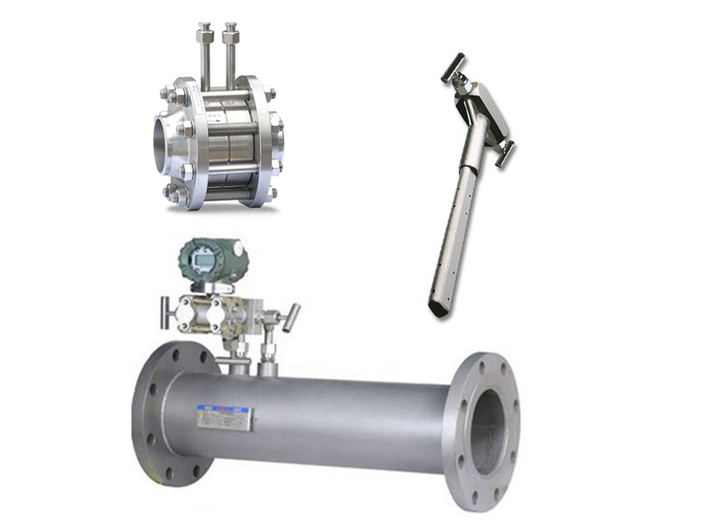
Differential Pressure Flow Meter Technology
Differential Pressure Flow Meters also called DP flow meters. Differential pressure flow meters consist of flow sensors and pressure/differential transmitters. DP Flow Meters measure the flow rate based on the differential pressure measured by the flow sensor parts. Flow sensors are the important part of differential pressure flow meters. Like: Orifice plate, Venturi tube, Wedge, V-cone and Averaging Pitot Tubes.
Differential pressure (DP) flow meters are suitable for applicaitons, like: water, gas, steam, oil….
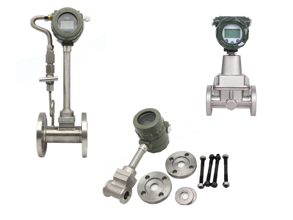
Vortex Flowmeter Technology
Vortex flow meters are suitable for measuring steam as well as a variety of liquids and gases. As fluid moves across a vortex meter shedder bar, vortices form. The frequency of the vortices shedding is proportional to the fluid velocity.
Even for the steam flow rate, Vortex flow meters are the perfect choice. Pressure and Temperature compensation ensure measurement accuracy. When measure steam or gas flow in pipes with variable operating pressure and temperature.
Applications in the chemicals and petrochemicals industries. For example, in power generation and heat-supply systems. Involve widely differing fluids: saturated steam, superheated steam, compressed air. Nitrogen, liquefied gases, flue gases, carbon dioxide, fully demineralized water. Solvents, heat-transfer oils, boiler feedwater, condensate, etc.
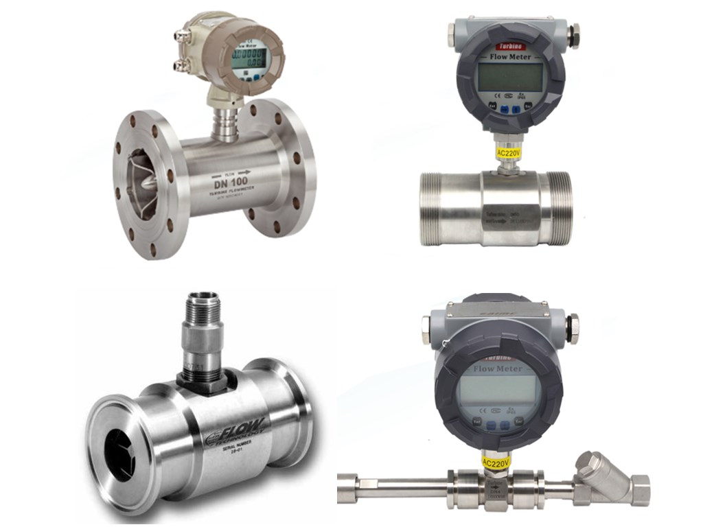
Turbine Flowmeter Technology
A turbine flow meter is a Volume flowmeter. Turbine flow meters use the mechanical energy of the liquid or gas to rotate a rotor in the flow stream. The velocity of the turbine rotor is proportional to the velocity of the fluid passing through the flow meter. The frequency of the signal relates directly to flow rate. The vaned rotor is the only moving part of the flow meter. Turbine flow meters measure the velocity of liquids, gases and vapors in pipes. Such as hydrocarbons, diesel, water, cryogenic liquids, air, and industrial gases.
Turbine flow meter is the most popular equipment to measure flow electronically. They offer a wide flow and application rangeability. Turbine Flow Meters are easy to maintain, durable and versatile.

Zhang Wei, possesses 20 years of experience as an automation instrumentation engineer, specializing in the research, design, installation, commissioning, and maintenance of automation instruments.
Face to various instrument communication protocols (such as Modbus, Profibus, etc.), with solid hardware circuit design and software programming skills (proficient in C language and PLC programming). Has extensive project experience; projects he has led and participated in have all achieved outstanding results, improving product accuracy, reducing costs, and increasing production efficiency.
Possesses excellent communication and coordination skills and a strong team spirit, enabling him to quickly respond to customer needs and provide high-quality automation instrumentation solutions.