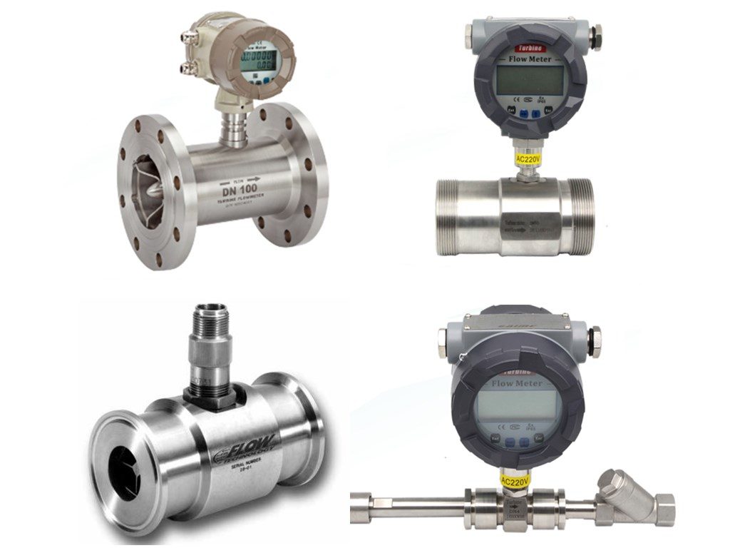
A turbine flow meter is a volume flowmeter that uses the mechanical energy of the liquid or gas to rotate a rotor in the flow stream. The velocity of the turbine rotor is proportional to the velocity of the fluid passing through the flow meter. The frequency of the signal relates directly to flow rate.
Turbine flow meters measure the velocity of liquids, gases and vapors in pipes, including hydrocarbons, diesel, water, cryogenic liquids, air, and industrial gases. The turbine flow meter is one of the most widely used devices to measure flow electronically. They offer a wide flow and application rangeability, are easy to maintain, durable and versatile.
Turbine flow meters are cost-effective and offer reliable, minimal flow meter maintenance required.
A turbine flow meter is a volume sensing device, constructed with rotor and blades. Turbine flow meters use the mechanical energy of the fluid to rotate the rotor in the flow stream. As liquid or gas passes through the turbine housing, it causes the freely suspended turbine blades to rotate. The velocity of the turbine rotor is proportional to the velocity of the fluid.
Rotor movement is often detected magnetically, where movement of the rotor generates a pulse. When the fluid moves faster, more pulses are generated. Turbine flow meter sensors detect pulses externally, outside the flowing stream, avoiding material-of-construction constraints associated with wetted sensors. The RPM of the turbine wheel is proportional to flow velocity within the tube diameter and corresponds to the volume flow over a wide range.
A flow transmitter mounted on the body of the flow meter. Transmitter processes the pulse signal to determine the flow of the fluid. Flow transmitter and sensing systems are available to sense flow in both the forward and reverse flow directions. High-accuracy models are available for custody transfer of hydrocarbons and natural gas.
When selecting a turbine flow meter, several application-specific factors must be considered:
Fluid Type
Viscosity
Connection
Pipe Sizing
Process Temperature (min & max)
Flow Range (min & max)
Pressure Range (min & max)
Accuracy Range
Specific Application
Sanitary or not
Local display
Signal output
If you need volumetric total flow and/or flow rate measurement, a turbine flow meter is the ideal device. Turbine flow meters are used in a wide variety of liquid and gas flow sensing applications. They can be built to endure high pressure, and high and low temperatures. They offer a high turn-down with minimum uncertainty and excellent repeatability. Turbine flowmeters are also simple to install and maintain only requiring periodic recalibration and service.
Turbine Measuring Principle
Theory of Operation
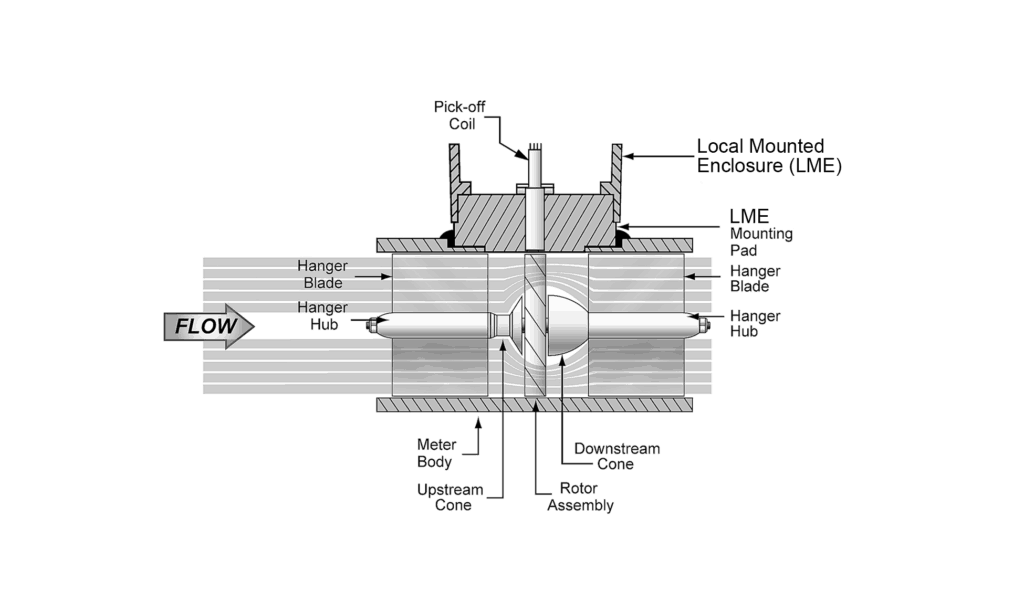
A turbine flow meter is used for volumetric total flow and/or flow rate measurement. Turbine flow meter has a simple working principle. As fluid flows through the turbine meter, it impinges upon turbine blades. These blades are free to rotate about an axis along the center line of the turbine housing. The angular (rotational) velocity of the turbine rotor is proportional to the fluid velocity. The resulting output is taken by an electrical pickoff(s) mounted on the flow meter body.
2. Because the blade of the impeller has a certain angle with the flow direction, the impulse of the fluid causes the blade to have a rotating moment.
3. Blades rotate after overcoming frictional torque and fluid resistance.
4. After the torque is balanced, the speed is stable.
5. Under certain conditions, the speed is directly proportional to the flow rate.
6. Because the blade is magnetically permeable, it is in the magnetic field of a signal detector (made of permanent magnetic steel and coils).
7. The rotating blade cuts the magnetic field lines and periodically changes the magnetic flux of the coil.
8. Thereby, an electric pulse signal is induced at both ends of the coil.
9. This signal is amplified and shaped by the amplifier to form a continuous rectangular pulse wave with a certain amplitude.
10. Remotely transmitted to the display instrument, show the instantaneous flow rate and cumulative amount of the fluid.
In a certain flow range, the pulse frequency f is proportional to the instantaneous flow Q of the fluid flowing through the sensor.
Turbine Flow Meter Equation
And the flow equation is: Q = 3600 × f / k
In the formula:
f——pulse frequency [Hz];
k——meter coefficient [1 / m] of the sensor, given by the checklist. If the unit is [1 / L] Q——the instantaneous flow of the fluid (in the working state) [m3 / h];
3600-conversion factor.
The meter factor of each sensor is filled in the verification certificate by the manufacturer.The k value is set in the matching display instrument, and the instantaneous flow rate and cumulative total can be displayed.
Totalizing Flow
The output frequency of the pickoff is proportional to the flow rate.Each electrical pulse is also proportional to a small incremental volume of flow. This is a major advantage of the turbine flow meter. This incremental output is digital in form. And as such, can be totalized with a maximum error of one pulse regardless of the volume measured. The rimmed rotor improves pulse resolution. Particularly in DN150 (6-in) and larger line size meters.
Achieving Repeatability
The turbine flow meter’s expanding blade hanger assembly holds the turbine rotor in alignment with the fluid flow. The angle of the turbine blades to the stream governs the angular velocity and the output frequency of the meter. Flow impinging upon the blade causes the rotor to spin at an angular velocity that is proportional to the flow rate. This design ensures linearity and repeatability. And make the turbine meter an ideal device for flow measurement. The short-term repeatability can reach 0.05 ~ 0.2%. It is precisely because of its good repeatability. Regular calibration or online calibration can achieve very high accuracy.
How Turbine Flowmeters Work
Turbine flowmeters use the mechanical energy of the fluid to rotate a “pinwheel” (rotor) in the flow stream. Blades on the rotor are angled to transform energy from the flow stream into rotational energy. The rotor shaft spins on bearings. When the fluid moves faster, the rotor spins proportionally faster. Turbine flowmeters now constitute 7% of the world market. Shaft rotation can be sensed mechanically or by detecting the movement of the blades. Blade movement is often detected magnetically, with each blade or embedded piece of metal generating a pulse.
Turbine flowmeter sensors are located external to the flowing stream to avoid material-of-construction constraints associated with wetted sensors. When the fluid moves faster, more pulses are generated. The transmitter processes the pulse signal to determine the flow of the fluid. Transmitters and sensing systems are available to sense flow in both the forward and reverse flow directions.
How Does a Turbine Flow Meter Work?
A turbine flow meter works by placing a free-spinning rotor in the flow path. As fluid passes through the meter body, it pushes against the angled rotor blades and causes the rotor to spin. The rotational speed is directly proportional to the volumetric flow rate of the fluid.
The rotor shaft typically carries a small magnet or ferromagnetic element. Each time the blade passes a pickup coil mounted on the meter housing, it generates an electrical pulse. A flow computer counts these pulses per unit time and converts them to a flow rate using the meter’s K-factor — a calibration constant expressed in pulses per unit volume.
Step-by-Step Signal Chain
Fluid enters the meter and hits the rotor blades at an engineered angle (typically 30–45°).
The rotor accelerates until drag forces balance the fluid-driven torque — this equilibrium speed is proportional to flow velocity.
A magnetic pickup coil detects each blade pass and outputs a frequency signal (pulse train).
The electronics module converts pulse frequency to instantaneous flow rate: Q = f / K, where f is pulse frequency (Hz) and K is the K-factor (pulses/liter or pulses/gallon).
Totalizer registers accumulate the pulse count to provide cumulative volume.
One practical consideration: turbine meters require a fully developed flow profile to produce accurate readings. Install at least 10 pipe diameters of straight pipe upstream and 5 diameters downstream. Flow conditioners can reduce this requirement to roughly 5D upstream in tight installations.
For gas measurement applications, pressure and temperature compensation is essential. Gas volume changes with operating conditions, so a flow computer with built-in P/T correction converts actual volume to standard volume (referenced to standard conditions, typically 15°C and 101.325 kPa).
Advantages & Disadvantages of Turbine Flow Meters
Like any flow measurement technology, turbine meters have clear strengths and limitations. Knowing both helps you avoid costly misapplication.
Turbine Meter Advantages
High accuracy — ±0.5% to ±1.0% of reading for liquids, making them suitable for custody transfer and fiscal metering.
Wide rangeability — Typical turndown ratio of 10:1 to 20:1, with some models reaching 30:1 under controlled conditions.
Fast response time — Millisecond-level response to flow changes, ideal for batch control and fast-cycling processes.
Low pressure drop — Streamlined rotor design creates minimal flow restriction compared to orifice plates or positive displacement meters.
Pulse output — Direct frequency signal simplifies totalizer integration without requiring A/D conversion.
Compact size — Shorter lay length than most Coriolis or ultrasonic meters at the same pipe size.
Proven reliability — Decades of field history in oil & gas, water distribution, and chemical processing.
Turbine Meter Disadvantages
Sensitive to dirty fluids — Suspended solids, fibrous material, or debris can damage rotor blades and bearings. A strainer upstream is strongly recommended.
Moving parts wear out — Bearings are the primary failure mode. Expect 5–10 year bearing life in clean service; much less in abrasive or poorly lubricated conditions.
Viscosity limitations — Performance degrades above 5–10 cSt. High-viscosity fluids cause under-reading and accelerate bearing wear.
Requires straight pipe runs — 10D upstream and 5D downstream minimum. Swirl, pulsation, and asymmetric profiles all cause measurement error.
Not suitable for two-phase flow — Entrained gas in liquid (or liquid droplets in gas) produces erratic readings and can over-speed the rotor.
Over-speed risk — Running above the maximum rated flow can permanently damage the rotor and bearings. Proper sizing is critical.
Applications for a Turbine Flow Meter
A turbine flow meter measures the velocity of liquids, gases and vapors in pipes.
Such as:
Oil and gas;
Water and wastewater;
Gas utility, chemical, power, food and beverage, aerospace, pharmaceutical;
Metals and mining;
Pulp and paper.
Fiscal and custody transfer, check metering or blending/batching;
Rude oil production;
Floating production, storage and off-loading (FPSO), refined product loading and offloading;
Low viscosity applications: Tap and demineralized water. Fuel flow meter solvents, Pharmaceutical fluids.
The repeatability of the meters ensures quality measurement. Over a wide range of flow rates, temperatures, compositions and viscosities.
High accuracy turbine flowmeters are available for custody transfer of hydrocarbons and natural gas.
A mass flow computer is often used in custody-transfer applications to correct for pressure, temperature and fluid properties. To achieve the desired accuracy.
Industries Where Used
Oil & Gas
Water injection
Test and production separators
Disposal wells
Hydraulic fracturing
Chemical injection
Natural gas pipelines
Aerospace/Defense
Engine Testing
Fuel flow measurement
Shipboard reverse osmosis systems
Monitor fuel supply to ship engines
Pharma-Bio Tech, Food & Beverage
Sanitary measurement
Pill coating
Power Generation
Custody transfer
Industrial & Municipal
Building automation
HVAC
Water metering
Cryogenics
Liquids measurement for plant applications and truck deliveries
How to Use Turbine Flowmeters
Turbine flowmeters measure the velocity of liquids, gases and vapors in pipes. Such as hydrocarbons, chemicals, water, cryogenic liquids, air, and industrial gases. For custody transfer of hydrocarbons and natural gas. High accuracy turbine flowmeters are available. These flowmeters often incorporate the functionality of a flow computer. To correct for pressure, temperature, fluid properties and achieve desired accuracy for application.
Be careful using turbine flowmeters on fluids that are non-lubricating. Because the flowmeter can become inaccurate and fail if its bearings prematurely wear. Some turbine flowmeters have grease fittings for use with non-lubricating fluids. Besides, turbine flowmeters that are designed for a specific purpose. Such as for natural gas service, can often operate over a limited range of temperature (such as up to 60ºC). Whereby operation at higher temperatures can damage the flowmeter.
This flowmeter can be applied to sanitary, relatively clean, and corrosive liquids in sizes up to approximately 24 inches. Smaller turbine flowmeters can be installed in the piping. But larger turbine flowmeters require the installation of substantial concrete foundations and supports. The flow of corrosive liquids can be measured with proper attention to the materials of construction of all wetted parts. Such as the body, rotor, bearings, and fittings.
Applications for turbine flowmeters are found in the water, petroleum, and chemical industries. Water applications include distribution systems within and between water districts. Petroleum applications include the custody transfer of hydrocarbons. Miscellaneous applications are found in the food and beverage, and chemical industries.
Application Cautions for Turbine Flowmeters
Turbine flowmeters are less accurate at low flow rates due to rotor/bearing drag that slows the rotor. Make sure to operate these flowmeters above approximately 5 percent of maximum flow. Turbine flowmeters should not be operated at high velocity. Because premature bearing wear and/or damage can occur. Be careful when measuring fluids that are non-lubricating. Because bearing wear can cause the flowmeter become inaccurate and fail. In some applications, bearing replacement may need to be performed routinely. And increase maintenance costs. Application in dirty fluids should generally be avoided so as to reduce the possibility of flowmeter wear and bearing damage. In summary, turbine flowmeters have moving parts that are subject to degradation with time and use.
Abrupt transitions from gas flow to liquid flow should be avoided. Because they can mechanically stress the flowmeter, degrade accuracy, and/or damage the flowmeter. These conditions generally occur when filling the pipe and under slug flow conditions. Two-phase flow conditions can also cause turbine flowmeters to measure inaccurately.
Turbine Flow Meter Calibration
“To calibrate” means “to standardize (as a measuring instrument) by determining the deviation from a standard so as to determine the proper correction factors.” There are two key elements to this definition: Determining the deviation from a standard. And ascertaining the proper correction factors.
Flow meters need periodic calibration. This can be done by using another calibrated meter as a reference or by using a known flow rate. Accuracy can vary over the range of the instrument. And with temperature and specific weight changes in the fluid, which may all have to be taken into account.
Thus, the meter should be calibrated over temperature as well as range. So that the appropriate corrections can be made to the readings. A turbine meter should be calibrated at the same kinematic viscosity at which it will be operated in service. This is true for fluid states, liquid and gas. In Volumetric Method technique, flow of liquid through the meter being calibrated is diverted into a tank of known volume. The time to displace the known volume is recorded to get the volumetric flow rate eg:- gallons per minute. This flow rate can then be compared to the turbine flow meter readings.
Turbine Flow Meter Price
Sino-Inst is a Turbine flow meter manufacturer, China. Sino-Inst offers over 10 turbine flow meter products. A wide variety of turbine flow meter options are available to you, to suit different applications and budgets. The price of turbine flow meters are decided by flollowing factors:
Pipe diameter;
Flow range;
Measured medium;
Whether it is corrosive;
Whether explosion protection is required;
Whether it needs local display;
Connection method;
Measure pressure;
Measure temperature;
Signal output;
Accuracy requirements;
Material requirements;
Turbine Flow Meter Application Selection Matrix
Choosing the right turbine flow meter starts with matching the meter specifications to your actual process conditions. The table below covers the most common application scenarios and the recommended configurations.
Application
Medium
Recommended Model
Key Spec Requirement
Notes
Water distribution
Clean water
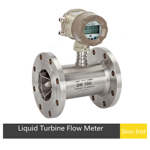
SI-3202 (Liquid)
DN25–DN200, ±1%
Standard 304SS housing is sufficient
Petroleum custody transfer
Diesel, gasoline, kerosene
SI-3202 (Liquid)
DN15–DN100, ±0.5%
Requires explosion-proof rating (Ex d IIB T6)
Natural gas metering
NG, LPG, biogas
SI-3201 (Gas)
DN25–DN200, with P/T comp
Must comply with AGA 7 or ISO 17089 for billing
Compressed air monitoring
Dry air, N2
SI-3201 (Gas)
DN15–DN100
Install after dryer and filter to protect rotor
Food & beverage
Milk, juice, syrup
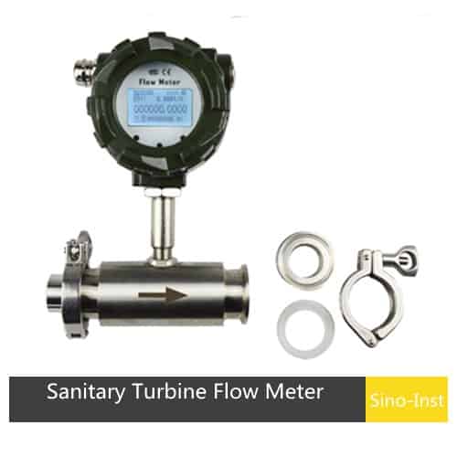
SI-3203 (Sanitary)
Tri-clamp connection, 316L
CIP-compatible, FDA-compliant wetted parts
Chemical dosing
Solvents, additives
SI-3204 (Flanged)
DN6–DN25, PTFE bearings
Check chemical compatibility before ordering
Hydraulic test stands
Hydraulic oil
SI-3202 (Liquid)
DN10–DN50, high-pressure rated
Viscosity compensation may be needed above 10 cSt
If your application is not listed above or involves unusual conditions (high viscosity, pulsating flow, two-phase flow), contact our engineering team for a custom recommendation. Turbine meters are not ideal for all situations — for slurry or highly viscous fluids, an electromagnetic flow meter or Coriolis meter is a better fit.
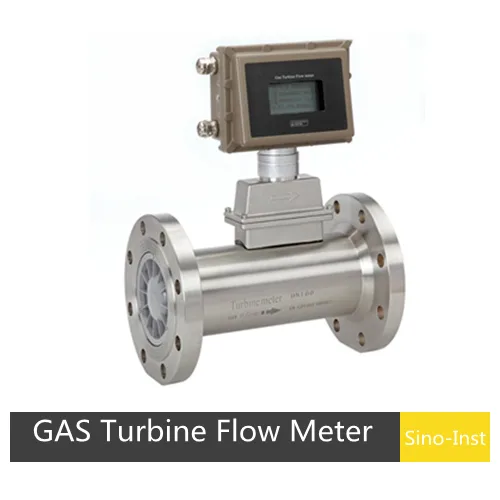
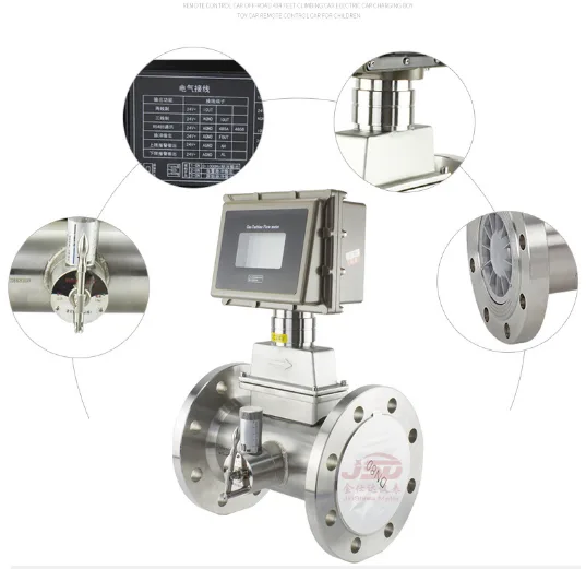
What Makes a Gas Turbine Flow Meter Different?
A gas turbine flow meter uses the same rotor principle as its liquid counterpart, but the mechanical and electronic design is optimized for low-density, compressible media. Because gas exerts much less force on the rotor blades than liquid does, gas meters use lighter rotors with thinner blades to maintain sensitivity at low flow velocities.
Key Differences: Gas vs Liquid Turbine Meters
Parameter
Gas Turbine Meter
Liquid Turbine Meter
Rotor material
Lightweight aluminum or titanium alloy
Stainless steel 304/316
Bearing type
Ball bearings or ceramic hydrodynamic
Sleeve or ball bearings, fluid-lubricated
Pressure compensation
Required — gas density changes with pressure
Typically not needed
Temperature compensation
Required — gas volume changes with temperature
Only for high-precision applications
Typical accuracy
±1.0% to ±1.5% of reading
±0.5% to ±1.0% of reading
Common applications
Natural gas custody transfer, compressed air, nitrogen, biogas
Pressure and temperature compensation matters because gas is compressible. A cubic meter of natural gas at 5 bar contains roughly 5 times more mass than a cubic meter at 1 bar. Without P/T correction, your totalizer reading would be meaningless for billing or process control. Most gas turbine meters either have built-in P/T sensors or accept external inputs from a pressure transmitter and temperature sensor.
For custody transfer of natural gas (ISO 17089 / AGA Report No. 7), gas turbine meters remain a popular choice because of their wide rangeability (typically 10:1 to 30:1), proven long-term stability, and relatively low pressure drop compared to orifice plates.
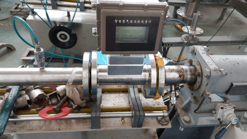
Sino-Inst’s SI-3201 Gas Turbine Flow Meter is available in DN15–DN200 sizes with optional built-in P/T compensation and HART or Modbus output.
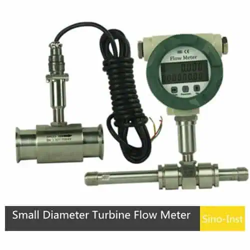
Low Flow Turbine Flow Meter
The SI-3207 small Diameter (small flow) liquid turbine flow meter,is a precision flow measuring instrument,that can be used to measure the flow and total volume of liquids. The structure is explosion-proof and can show the total flow, instantaneous flow and percentage of flow fullness.It is widely used in measurement and control systems in petroleum, chemical, metallurgical, scientific research and other fields. Sensors equipped with sanitary fittings can be used in the pharmaceutical industry.
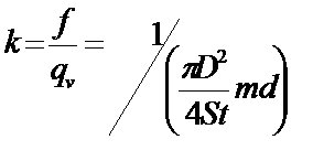
How do you calculate K factor for a turbine flow meter?
There are two different manufacturers k: one is k = f / Q, which is the number of vortices generated per unit flow; the other is k = Q / f, which is the flow corresponding to each vortex. The k value is calibrated by the factory water. The number of vortices of the sensor measuring instrument is compared with the volume flow measured by the calibration device to obtain the k value.
St —- Strauhal number, constant in a certain range of Reynolds number
d —- characteristic width of vortex generator
m–the ratio of the arcuate area on both sides of the vortex generator to the cross-sectional area inside the pipe
The values of d and m are difficult to measure accurately, so it is difficult to obtain accurate k values by calculation.
Turbine Flow Meter vs Flow Sensor vs Flow Transmitter: What Is the Difference?
These three terms often appear interchangeably in search results, but they refer to different levels of a measurement system. Understanding the distinction helps you specify the right product for your application.
Term
What It Is
Output Signal
Typical Use Case
Turbine Flow Meter
Complete measurement instrument with rotor, housing, and readout electronics
Pulse output, 4–20 mA, or display
Standalone flow measurement with local or remote indication
Turbine Flow Sensor
Rotor assembly + pickup coil only — no signal conditioning electronics built in
Raw pulse signal (mV level)
OEM integration where the host system provides signal processing
Turbine Flow Transmitter
A flow meter with built-in signal conditioning that outputs a standardized signal (4–20 mA, HART, RS485)
4–20 mA, HART, Modbus
Process control loops, PLC/DCS integration, SCADA systems
In practice, most industrial turbine flow meters sold today include transmitter-level electronics — meaning they output 4–20 mA or digital signals out of the box. When you see “turbine flow sensor” in a product listing, it usually means a simpler unit intended for OEM or cost-sensitive applications where the user supplies their own signal processing.
At Sino-Inst, our SI-3201 and SI-3202 models ship with integrated electronics and can be configured as either pulse-output meters or 4–20 mA transmitters, depending on your control system requirements.
Frequently Asked Questions
What is the accuracy of a turbine flow meter?+
Most turbine flow meters achieve ±0.5% to ±1.5% of reading, depending on the model and calibration. Liquid meters tend to be more accurate (±0.5–1.0%) than gas meters (±1.0–1.5%). Accuracy also depends on proper installation with adequate straight pipe runs.
How long does a turbine flow meter last?+
With clean fluid and proper installation, a turbine flow meter bearing typically lasts 5–10 years. The rotor itself rarely fails. Bearing wear is the primary life-limiting factor and is accelerated by dirty fluid, over-speeding, or insufficient lubrication in gas applications.
Can a turbine flow meter measure bidirectional flow?+
Standard turbine meters measure flow in one direction only. Some models can detect reverse flow, but the accuracy specification only applies in the forward direction. For true bidirectional measurement, consider an ultrasonic or electromagnetic flow meter.
What is the minimum flow rate for a turbine meter?+
The minimum measurable flow (lower range limit) depends on the meter size. For a DN25 liquid turbine meter, it is typically around 0.6–1.0 m³/h. Below this threshold, the fluid does not generate enough torque to spin the rotor consistently. Oversizing the meter is a common mistake that pushes operating flow below this limit.
Does fluid viscosity affect turbine meter readings?+
Yes. Turbine meters are calibrated for a specific viscosity range, usually below 5 cSt. As viscosity increases, the rotor drag increases, and the meter under-reads. Above 10 cSt, accuracy degrades significantly unless viscosity compensation is applied. For high-viscosity fluids (above 30 cSt), a positive displacement or Coriolis meter is a better choice.
How often should a turbine flow meter be calibrated?+
Most industry guidelines recommend annual calibration for custody transfer and fiscal metering. For process control applications, every 2–3 years is acceptable if the meter is installed in clean fluid and operating within its rated range. Sudden shifts in K-factor during operation usually indicate bearing wear or rotor damage.
Best Technology Guide to Thermal Mass Flow Meters. A thermal mass flowmeter (TMF) is a gas flowmeter designed based on the principles of thermal diffusion or heat conduction. It directly measures the mass flow of gas without the need for…
Flow meters measure the volume or mass of liquid, gas, or steam moving through a piping system. There are many different flow meter technologies, and each delivers different accuracy. The accuracy requirements for a flow meter depend a great deal…
Best Technology Guide to Ultrasonic Flow Meters. An ultrasonic flow meter is a volumetric flow meter that measures the flow rate of a medium based on the effect of the flowing medium on the ultrasonic velocity or ultrasonic pulse. There…
Coriolis Mass Flow Meter — Working Principle, Installation & Price. A Coriolis mass flow meter reads the Coriolis effect to measure mass flow directly — the same physics a fuel depot uses to prove a tanker’s load or a chemical…
Differential Pressure Flow Meters (also called DP flow meters or differential flow meters) measure flow rate by detecting the pressure drop across a restriction in the pipe. A throttling device — such as an orifice plate, Venturi tube, wedge, V-cone,…
Best Technology Guide to Vortex Flow Meters. Vortex flow meter is a kind of velocity flowmeter, based on the Karman (Von Kármán Effect designed by vortex principle research). It is mainly used for flow measurement of medium fluid in industrial…
Zhang Wei, possesses 20 years of experience as an automation instrumentation engineer, specializing in the research, design, installation, commissioning, and maintenance of automation instruments.
Face to various instrument communication protocols (such as Modbus, Profibus, etc.), with solid hardware circuit design and software programming skills (proficient in C language and PLC programming). Has extensive project experience; projects he has led and participated in have all achieved outstanding results, improving product accuracy, reducing costs, and increasing production efficiency.
Possesses excellent communication and coordination skills and a strong team spirit, enabling him to quickly respond to customer needs and provide high-quality automation instrumentation solutions.