Vortex Flow Meter Technology
Best Technology Guide to Vortex Flow Meters.
Vortex flow meter is a kind of velocity flowmeter, based on the Karman (Von Kármán Effect designed by vortex principle research). It is mainly used for flow measurement of medium fluid in industrial pipelines, such as flow control and metering of various media such as gas, steam or liquid.
Vortex flow meter has irreplaceable advantages, extremely high sensitivity, and the lower limit of gas flow rate can be as low as 2m/s. It is widely used in the metering and control of superheated steam, saturated steam, compressed air, and general gas (oxygen, nitrogen, hydrogen, natural gas, coal gas, etc.), water and liquid (such as: water, gasoline, alcohol, benzene, etc.).
Featured Products
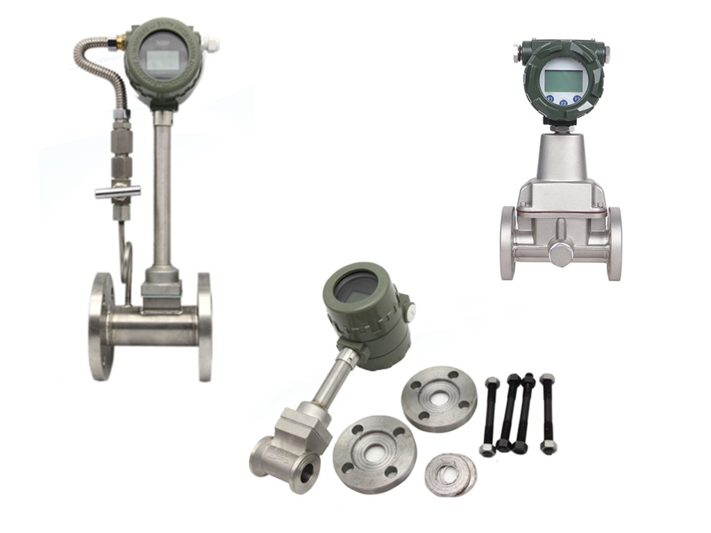
Sino-Inst vortex flow meters offer outstanding reliability in measuring gas, liquid and steam flow. We supply pipeline type (flange, Wafer), insertion type vortex flowmeter, and new type of swirl vortex flowmeter.
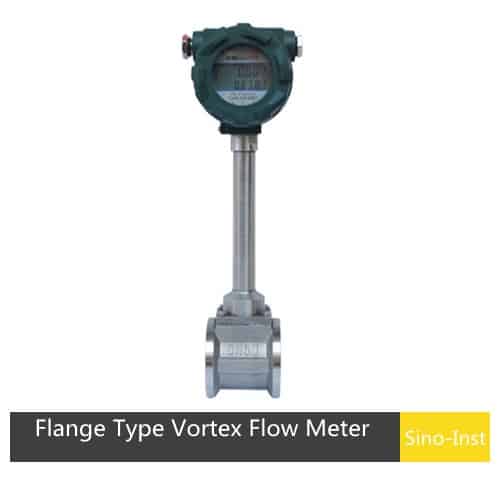
SI-3301 Gas Vortex Flow Meter
SI-3301 digital gas vortex flow meter is a flow meter operating with Karman Vortex principle for flow rate of gases (air, oxygen, nitrogen, coal gas, natural gas, chemical gas, etc.). It could be used in automatic control system as flow transmitter.
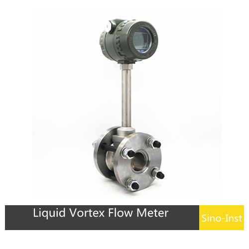
SI-3302 Liquid Vortex Flow Meter
SI-3302 Liquid Vortex Flow Meter is a flow meter operating with Karman Vortex principle for flow rate of liquids (water, high temperature water, oil, beverage, chemical liquids, etc.). It could be used in automatic control system as flow transmitter. SI-3302 liquid flow meter is also with unique sensor encapsulation and protection technology to ensure service life of the sensor.
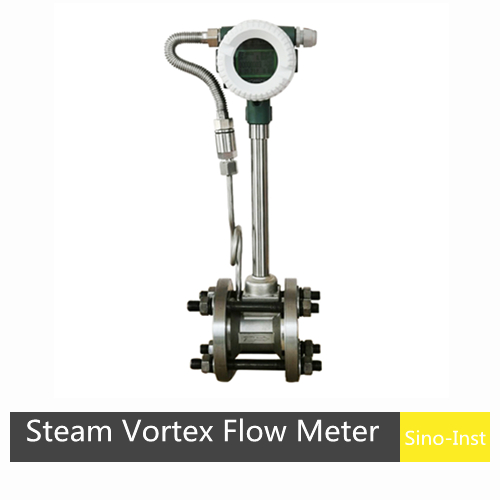
SI-3303 Steam Vortex Flow Meter
SI-3303 digital steam vortex flow meter is a flow meter operating with Karman Vortex principle for flow rate of steams (saturated steam, superheated steam, etc.). It could be used in automatic control system as flow transmitter. SI-3303 steam flow meter is also with unique sensor encapsulation and protection technology to ensure service life of the sensor.
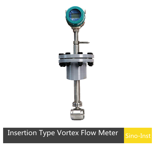
SI-3304 Insertion Type Vortex Flow Meter
SI-3304 Insertion Type Vortex Flow Meter is designed for large pipeline size over 10 inches, users can install and removal the vortex sensor without closing down the whole running system. Customers can get volumetric or mass flow of gas, air or steam through our powerful vortex flow meter
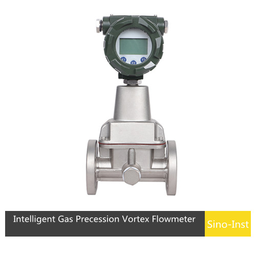
SI-3305 Intelligent Gas Precession Vortex Flowmeter
SI-3305 Intelligent Gas Precession Vortex Flowmeter is a new type of gas flow meter. It has the function of measuring flow, temperature, and pressure; it also can compensate temperature, pressure and compressible factor automatically. It is an ideal instrument of gas measurement, which is used for petroleum, chemical industrial, electricity, metallurgy, and so on.
What is a Vortex Flow Meter?
Vortex flowmeters are also known as vortex shedding flowmeters or Karman vortex flowmeters. Vortex flowmeters are volumetric flowmeters used to measure volumetric flow, standard volumetric flow, or mass flow of gases, steam, or liquids.
Vortex flowmeters work on the principle of vortex shedding. When a fluid, such as water, flows over a blunt body (rather than a streamlined shape), an oscillating vortex is generated. The vortices are alternately shed downstream of the object. The frequency of vortex shedding is proportional to the velocity of the liquid flowing through the flowmeter.
Vortex flowmeters are suitable for flow measurement where it is difficult to introduce moving parts. Vortex flowmeters are available in industrial grade, brass, or all-plastic. They have low sensitivity to changes in process conditions and have no moving parts. They have relatively low wear compared to other types of flowmeters.
Vortex flowmeters are ideal for applications where low maintenance costs are important. Industrial grade vortex flowmeters are custom-made and need to be sized appropriately for the specific application.
Vortex flow meter working principle
How does a vortex flow meter work? When a triangular prism-shaped vortex generator is set in the fluid, regular vortices are generated alternately from both sides of the vortex generator. This vortex is called a Karman vortex. The vortex array is arranged asymmetrically downstream of the vortex generator.
The working method of the vortex flowmeter is relatively simple, and its process is as follows:
- When the fluid passes through the vortex blades, vortices are generated, and the number of vortices is proportional to the fluid flow rate;
- The vortex blades vibrate under the action of the vortex;
- The vortex sensor detects and measures the frequency and amplitude of the vortex vibration;
- The signal processor converts the frequency and amplitude measured by the vortex sensor into a flow value.
Next, let’s take a closer look at its principles and calculation formulas.
When a non-streamlined vortex generator (baffle body) is set in the fluid, two regular vortices are generated alternately from both sides of the vortex generator. This vortex is called Karman vortex effect, as shown in the figure below.

The vortex columns are arranged asymmetrically downstream of the vortex generator. Assume that the frequency of vortex generation is f, the average velocity of the measured medium is V, the width of the vortex generator’s frontal surface is d, and the diameter of the body is D. According to the Karman vortex effect principle, there is the following relationship:
f=StV/d
Where:
- f- Karman vortex frequency generated on one side of the generator
- St- Strouhal number (dimensionless number)
- V-average flow rate of the fluid
- d-width of the vortex generator
It can be seen that the instantaneous flow rate can be calculated by measuring the Karman vortex separation frequency. Among them, the Strouhal number (St) is a dimensionless unknown number. The following figure shows the relationship between the Strouhal number (St) and the Reynolds number (Re).

In the straight part of the curve St=0.17, the release frequency of the vortex is proportional to the flow rate, which is the measurement range of the vortex flow sensor. As long as the frequency f is detected, the flow rate of the fluid in the pipe can be obtained. The volume flow rate is calculated from the flow rate V. The ratio of the measured pulse number to the volume is called the instrument constant (K), see the formula:
K=N/Q(1/m³)
Where:
- K=Instrument constant (1/m³).
- N=Number of pulses
- Q=Volume flow rate (m)
vortex flow meter advantages and disadvantages
Advantages:
- The main body of the product has no moving parts, high reliability, long-term stability, simple structure and easy maintenance;
- The sensor output is a pulse frequency, and its frequency is linear with the actual flow rate of the measured fluid. There is no zero point drift and the performance is very stable.
- The structure is diverse, including pipeline type, insertion type flow sensor and other forms;
- High accuracy, the measurement accuracy of conventional liquid is ±1.0%; the measurement accuracy of gas is ±1.5%;
- Small pressure loss (about 1/4-1/2 of the orifice flowmeter), belonging to the energy-saving flow meter;
- Flexible installation method, according to the different process pipelines on site, it can be installed horizontally, vertically or at different angles;
- Wide measurement range, the range ratio can reach 1:8~1:30;
- The volume flow of the vortex flowmeter is basically not affected by the temperature, pressure, density, viscosity and other parameters of the measured fluid.
Disadvantages:
- Uneven flow rate in the pipeline can easily cause measurement errors;
- Failure to accurately determine the density of the medium when the fluid working conditions change can also easily cause measurement errors.
- Poor vibration resistance. External vibration can cause measurement errors of the vortex flowmeter, or even fail to work properly. The high-speed impact of the channel fluid will cause additional vibration to the cantilever of the vortex generator, thereby reducing the measurement accuracy. The impact of large pipe diameters is more obvious.
- Poor adaptability to measuring dirty media. The generator of the vortex flowmeter is easily dirty or entangled by the medium, and the change in the size of the geometric body has a great impact on the measurement accuracy.
- High requirements for straight pipe sections. In order to ensure measurement accuracy, the vortex flowmeter needs to ensure a straight pipe section of 40D in front and 20D in the back to meet the measurement requirements.
- Poor temperature resistance. The vortex flowmeter can generally only measure the fluid flow of media below 350℃.
Vortex flow meters measure fluid velocity using a principle of operation referred to as the von Kármán effect. When flow passes by a bluff body, a repeating pattern of swirling vortices is generated.
Von Kármán Effect is an important phenomenon in fluid mechanics. It is often encountered in nature. When a steady flow under certain conditions passes around certain objects, the two sides of the object will periodically shed double-row line vortices with opposite rotation directions and regular arrangement. After nonlinear action, a Karman vortex is formed.
For example, when water flows over bridge piers, wind blows over high towers, chimneys, and electric wires, Karman vortex will be formed. Karman vortex effect have some very important applications, so it is necessary to understand its research history and related applications.
The K factor of a vortex flowmeter indicates the number of pulses output by the vortex flowmeter when a unit volume (or mass) of fluid passes through it. The unit is usually pulses/cubic meter (P/m³) or pulses/liter (P/L).
The instrument factor K value of the vortex flowmeter has been debugged and tested before leaving the factory. The instrument constant k of each flowmeter is indicated on the nameplate and factory certificate. Its physical meaning is that under the calibration state (P = 101.3kPa, t = 20℃), for each liter of volume flow passing through the flowmeter, the number of pulses output by the flowmeter is 1/L.
Formula: K=f/Q
f: Pulse frequency output by vortex sensor (Hz)
Q: Instantaneous flow rate (m’/h or L/s)
Example:
If K=1000P/m³, when the flow rate is 10m³/h, the output pulse frequency is:
f=K*Q=1000×10=10,000P/h≈2.78Hz
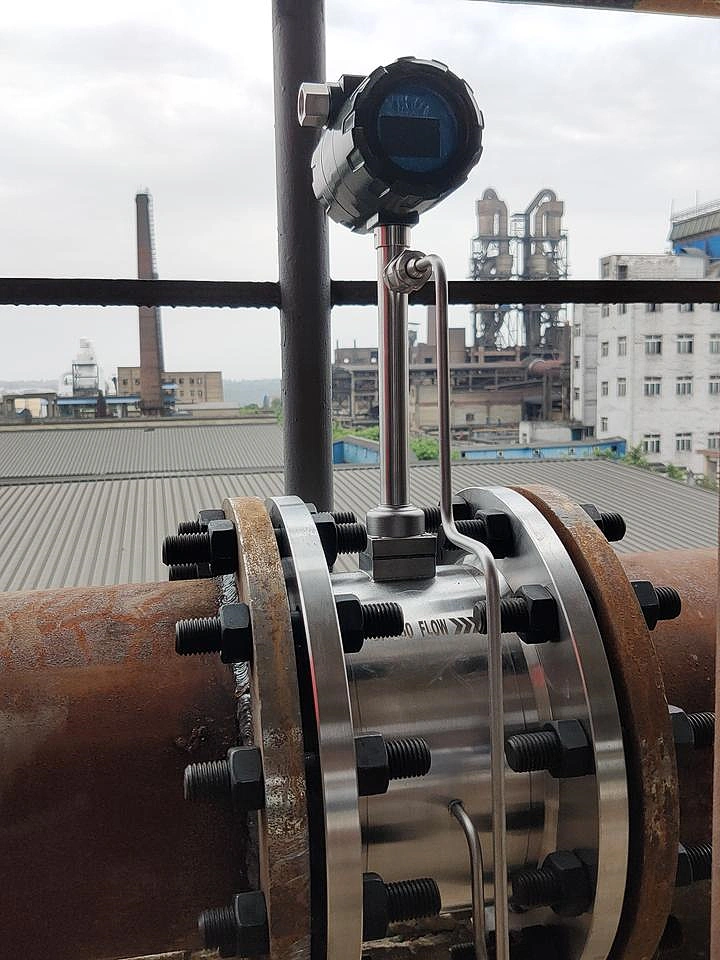
Vortex flow meter installation
Vortex flow meter can be installed horizontally, vertically, or tilted on the pipeline. However, we must also pay attention to the requirements of the front and rear straight pipe sections, as well as some installation details. Otherwise, it will affect the smoothness of the medium in the pipeline and affect the measurement accuracy of the instrument.
Precautions for installing vortex flow meter:
1. Reasonably select the installation location and environment of the vortex flowmeter. Consider the convenience of installation and maintenance at the same time. Avoid strong electrical equipment, high-frequency equipment, and strong electrical switch equipment. Avoid the influence of high-temperature heat sources and radiation sources. Avoid strong vibration places, strong corrosive environments, etc.
2. There must be enough straight pipe sections upstream and downstream.
- If the sensor installation point of the vortex flowmeter is located upstream of two 90° elbows in the same plane, then: the upstream straight pipe section ≥25D, and the downstream straight pipe section ≥5D.
- If there are two 90° elbows in different planes upstream of the sensor installation point, then: the upstream straight pipe section ≥25D.
- Elbow, then: the upstream straight pipe section ≥40D, and the downstream straight pipe section ≥5D.
- The regulating valve should be installed 5D downstream of the sensor.
- If it must be installed upstream of the sensor, the upstream straight pipe section of the sensor should not be less than 50D, and the downstream should not be less than 5D.

3. The upstream and downstream pipelines of the installation point should be concentric with the sensor, and the coaxiality deviation should not be less than 0.5DN.
4. Take vibration reduction measures for the pipeline. Try to avoid installing the sensor on pipelines with strong vibration. Especially on pipelines with large lateral vibration.
If it must be installed, vibration reduction measures must be taken. And pipeline fastening devices should be installed 2D upstream and downstream of the sensor, and anti-vibration pads should be installed.
5. Horizontal pipeline installation is a common installation method for flow sensors.
When measuring gas flow, if the measured gas contains a small amount of liquid, the sensor should be installed at a higher position in the pipeline.
When measuring liquid flow, if the measured liquid contains a small amount of gas, the sensor should be installed at a lower position in the pipeline.
6. Installation of the sensor in a vertical pipeline.
When the vortex flowmeter measures gas flow, the sensor can be installed on a vertical pipeline, and the flow direction is not restricted.
If the measured gas contains a small amount of liquid, the gas flow direction should be from bottom to top.
When measuring liquid flow, the liquid flow direction should be from bottom to top: this will not add extra liquid weight to the probe.
7. The sensor is installed on the side of the horizontal pipe. Regardless of the fluid being measured, the sensor can be installed sideways on the horizontal pipe. It is especially suitable for measuring superheated steam, saturated steam and low-temperature liquids. If conditions permit, side installation can be used, and the fluid temperature has less effect on the amplifier.
8. The sensor is inverted on the horizontal pipe. This installation method is generally not recommended. This installation method is not suitable for measuring general gases and superheated steam. It can be used to measure saturated steam, suitable for measuring high-temperature liquids or occasions where the pipeline needs to be cleaned frequently.
9. Install the sensor on the insulated pipe. When measuring high-temperature steam, the height of the insulation layer shall not exceed one-third of the height of the bracket.
10. Selection of pressure and temperature measurement points. According to the measurement needs, when it is necessary to measure pressure and temperature near the sensor, the pressure measurement point should be located 3-5D downstream of the sensor. The temperature measurement point should be located 6-8D downstream of the sensor.
Vortex flow meter price
The price of vortex flowmeters is affected by the following measurement conditions:
1. Pipeline diameter
2. Accuracy requirements
3. Measure the pressure
4. Measure the temperature
5. Output signal
6. Whether explosion-proof
Key Elements to Consider before Choosing a Vortex Flow Meter
- What is the fluid being measured?
- Pressure Maximum and Minimum
- Flowrate Ranges
- Fluid Temperature
- Fluid Density Range
- Viscosity Range
- Pipe Size
- Maximum Acceptable Pressure Drop
- Pipe Schedule or Wall Thickness
- Pipe Material
- Nearest Upstream Obstruction
Vortex Flow Meters Applications
Vortex flowmeters are widely used in industrial circulation, sewage treatment, and oil flow measurement of large, medium and small pipelines. Vortex flowmeters are also frequently used for measurement in steam, saturated steam, and superheated steam. They can be specifically applied to Flow measurement in the following occasions
1. Flow measurement of steel plant and coke oven gas;
2. Measurement of air flow and secondary air volume of the boiler;
3. Flue gas flow measurement of the chimney;
4. Measurement of aeration flow in water treatment;
5. Gas flow measurement during the production process of cement plants, cigarette factories and glass factories;
6. Compressed air flow measurement in the compressor;
7. Gas, liquefied gas, flare gas, hydrogen, and other gas flow measurement
More Flow Measurement Solutions
- Flowmeter Calibration & Recalibration
- Ultrasonic Flow Meter Technology
- Thermal Mass Flow Meter Technology
- Coriolis Mass Flow Meter Technology
- Differential Pressure Flow Meter Technology
- Turbine Flowmeter Technology
- Magnetic Flowmeter Technology
Vortex flowmeter is a commonly used flowmeter. Its principle is to use the vortex generated by the vortex to measure the fluid flow. The above is our comprehensive analysis of the vortex flowmeter, including its principle, structure, working mode, application range, advantages and disadvantages. I hope it may help you choose a suitable vortex flowmeter.
Vortex flowmeter has excellent performance in many aspects, but it also needs to be selected according to actual use needs. Sino-Inst supports various parameter customization of vortex flowmeter. If you need to purchase or have related technical questions, please feel free to contact our sales engineer!

Zhang Wei, possesses 20 years of experience as an automation instrumentation engineer, specializing in the research, design, installation, commissioning, and maintenance of automation instruments.
Face to various instrument communication protocols (such as Modbus, Profibus, etc.), with solid hardware circuit design and software programming skills (proficient in C language and PLC programming). Has extensive project experience; projects he has led and participated in have all achieved outstanding results, improving product accuracy, reducing costs, and increasing production efficiency.
Possesses excellent communication and coordination skills and a strong team spirit, enabling him to quickly respond to customer needs and provide high-quality automation instrumentation solutions.