Home > Technologies > Differential Pressure Flow Meter Technology
Differential Pressure Flow Meter Technology
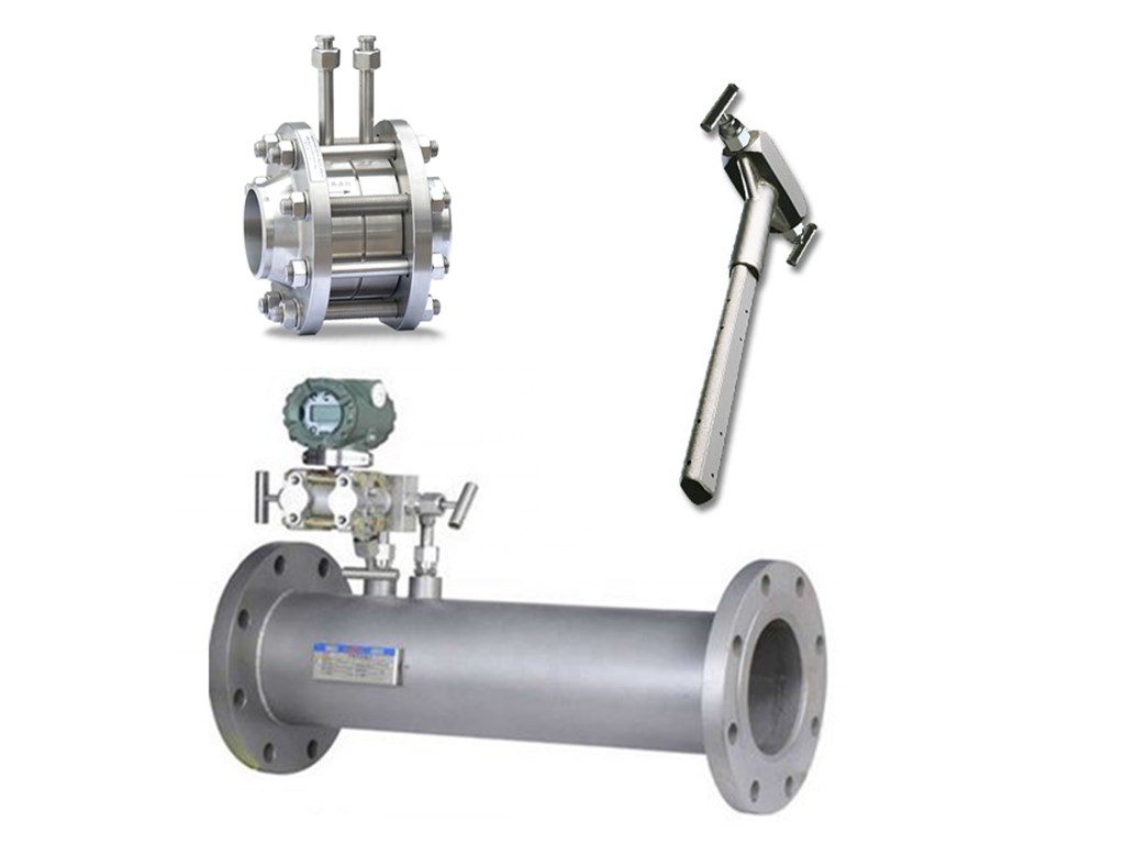
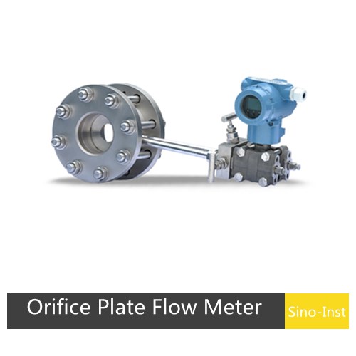
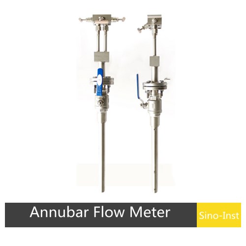
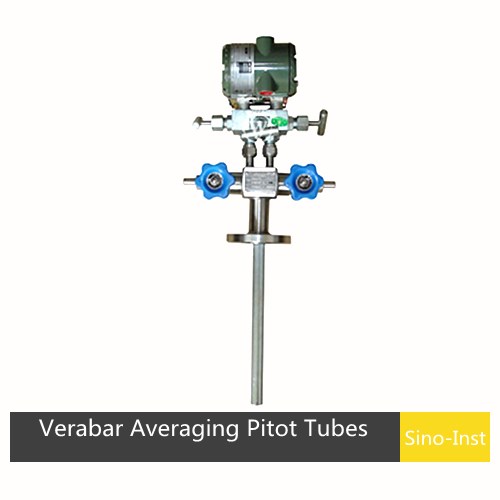
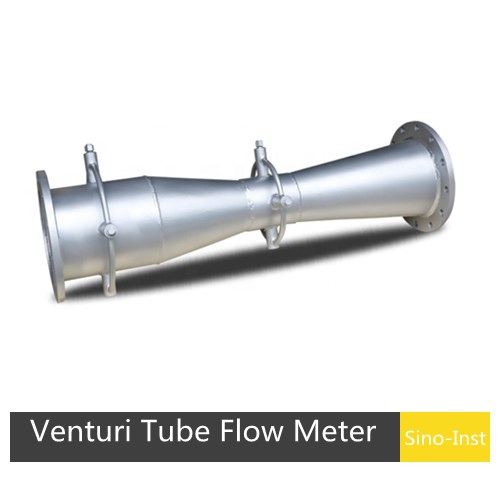
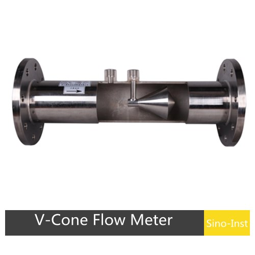
Differential Pressure Flow Meters (also called DP flow meters or differential flow meters) measure flow rate by detecting the pressure drop across a restriction in the pipe. A throttling device — such as an orifice plate, Venturi tube, wedge, V-cone, or averaging Pitot tube — creates this pressure drop. The bigger the flow, the bigger the pressure difference. A DP transmitter reads that difference and converts it to a flow signal. These pressure flow meters handle water, gas, steam, oil, and many chemical processes.
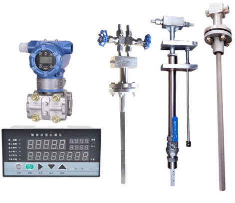
A differential pressure flow meter works by placing a restriction inside a pipe. Fluid speeds up as it passes through the narrowed section, and the static pressure drops. A DP transmitter picks up the pressure on each side of the restriction and calculates the difference. That differential pressure is directly related to how fast the fluid is moving. The basic setup has three parts: a throttling device (the restriction), impulse tubing (the signal lines), and a differential pressure transmitter or gauge.
Throttling devices come in several forms: orifice plates (the most common), Venturi tubes, flow nozzles, wedge elements, V-cones, and averaging Pitot tubes. Among these, orifice plates with corner taps or flange taps, and ISA 1932 nozzles, are classified as standard primary elements under ISO 5167. “Standard” means you can calculate the discharge coefficient from published equations without wet-calibrating the device — a significant cost advantage on large pipe sizes.
Differential pressure flow meters have a wide range of applications. All single-phase fluids can be measured, including liquid, gas, and steam. Partial miscible flows such as gas-solid, gas-liquid, and liquid-solid mixtures can also be measured. The most common application is the standard orifice plate flowmeter.
Differential Pressure Flow Meter Types
Primary Element
Recommended Service
Min RE Limits
Size
Advantages
Limitations
Square edge concentric orifice plate
Clean liquids, gases, steam
\u22652000
\u22651/2 in
Easy to install; Low cost; Easy to replace
Long relaxation piping; High head loss; Accuracy affected by installation conditions
Conical/quadrant edge concentric orifice plate
Viscous liquids
\u2265500
1 to 6 in
Easy to install; Low cost; Easy to replace
Long relaxation piping; High head loss
Eccentric/segmental orifice plate
Liquids and gases with secondary fluid phases
>10,000
4 to 14 in
Easy to install; Low cost; Easy to replace
Long relaxation piping; High head loss; Higher discharge coefficient uncertainty
Integral orifice
Clean liquids, gases, steam
>10,000
1/2 to 2 in
Easy to install; Low cost; No lead lines
Proprietary design requires calibration; More prone to clogging
Venturi/flowtube
Clean & dirty liquids, gases, steam; slurries
>75,000
1/2 to 72 in
Low head loss; 2-9x less relaxation piping than orifice; Higher flow capacity
High initial cost
Nozzle
Clean liquids, gases, steam
>50,000
\u22652 in
Higher flow capacity than orifice; Good for high temperature and velocity
Advantages and Disadvantages of Differential Pressure Flow Meters
The upside of this technology is low cost. Multiple versions can be optimized for different fluids and goals, are approved for custody transfer, and it is a well-understood way to measure flow. It can be paired with temperature/pressure sensors to provide mass flow for steam and other gases.
Negatives are that rangeability is not good due to a non-linear differential pressure signal (laminar flow elements excepted). Accuracy is not the best and can deteriorate with wear and clogging.
Advantages of Throttling DP Flowmeters (Orifice Flowmeters)
Standard orifice plate structure is easy to replicate. Simple, sturdy, stable, and reliable in performance with long service life and low price.
Applicable to an extremely wide range of fluids: all single-phase fluids including liquid, gas, and steam. Some mixed-phase flows (gas-solid, gas-liquid, liquid-solid) can also be measured.
Standard throttling devices are recognized by international standards organizations and can be put into use without actual flow calibration.
Disadvantages of Throttling DP Flowmeters
Repeatability and accuracy are at medium levels.
Narrow range: general range is only 3:1 to 5:1 due to squared relationship between signal and flow rate.
Requires long straight pipe sections upstream and downstream, which can be difficult to meet on-site.
Pressure piping is a weak link, prone to leakage, blockage, freezing, and signal distortion.
Pressure loss is relatively large.
Differential Pressure Flow Meter Working Principle
Working Principle of Differential Pressure Flow Meters
The DP flow meter working principle is based on Bernoulli’s equation. Place a restriction in the pipe — an orifice plate, a Venturi, a wedge, whatever fits the job — and the fluid accelerates through the narrowed section. That acceleration trades pressure energy for velocity energy. The upstream pressure stays high; the downstream pressure drops. The bigger the flow rate, the bigger the pressure difference. Impulse piping routes the upstream and downstream pressures to the differential pressure transmitter, which measures the differential pressure and indicates the fluid flow.
Bernoulli’s equation tells us that pressure drop across the constriction is proportional to the square of the flow rate. The basic differential pressure flow meter equation is: Q = K × √(ΔP), where Q is the volumetric flow rate, K is a coefficient that accounts for pipe size, fluid density, and the discharge coefficient of the element, and ΔP is the measured differential pressure. One practical consequence: at 10% of full scale flow, only 1% of the full scale differential pressure is produced. DP transmitter accuracy degrades at low differential pressures, so the flow measurement gets less reliable at the bottom end of the range. That is why most DP flow meters have a practical turndown of about 3:1 to 5:1.
Different geometries are used for different measurements, including the orifice plate, flow nozzle, laminar flow element, low-loss flow tube, segmental wedge, V-cone, and Venturi tube.
Differential Pressure Flow Meter Equation
The key relationships in differential pressure flow measurement are: Q = C × A₂ × √(2ΔP / ρ), where C is the discharge coefficient, A₂ is the throat area of the restriction, ΔP is the differential pressure, and ρ is the fluid density. In practice, the discharge coefficient depends on the Reynolds number and the beta ratio (β = d/D, the ratio of restriction bore to pipe diameter). For standard orifice plates, C typically falls between 0.59 and 0.65. For Venturi tubes, it is higher — around 0.95 to 0.99 — which is why Venturis have much lower permanent pressure loss.
How Is Differential Pressure Related to Flow Rate?
Differential pressure flowmeters use Bernoulli’s equation to measure fluid flow in a pipe. They introduce a constriction that creates a pressure drop. When flow increases, more pressure drop is created.
How to Measure Differential Pressure
When fluid hits the throttling device, the flow area shrinks. Conservation of mass says the velocity must go up. Conservation of energy (Bernoulli) says the pressure must come down. A pressure tap upstream and another downstream capture that difference. The differential pressure signal line carries both pressures to the DP transmitter, which does the subtraction and outputs a signal. Bigger flow means bigger velocity change, which means a bigger pressure drop — that is how differential pressure flow measurement works in every installation from a 1/2-inch lab line to a 72-inch water main.
Differential Pressure Flow Meter Applications
The flexibility of differential pressure flowmeters makes them suitable for extremely diverse industrial flow applications:
Water and Wastewater: Flow monitoring in treatment plants, lift stations, and distribution systems
Power Generation: Feedwater, condensate, cooling water, steam flow, stack emissions
Chemicals and Petrochemicals: Production monitoring, mixing/batching, loading rack measurement
Pulp and Paper: Digester flow, black liquor, steam flow, custody transfer
Food and Beverage: Batching, sanitary production lines, plant energy management
Pharmaceuticals: Clean process liquids, transfers, batching
HVAC: Chilled water, hot water, steam, compressed air, ventilation balance
Steam and gas applications deserve extra attention. In steam service, the fluid density changes with temperature and pressure, so a single DP reading is not enough. You need live pressure and temperature compensation — typically a multivariable transmitter or a flow computer that receives separate P and T inputs. Saturated steam below 150°C often works fine with a standard orifice plate and a compensated DP transmitter. Superheated steam or high-pressure gas lines (above 40 bar) may need a Venturi or V-cone to minimize permanent pressure loss. For flare gas measurement, averaging Pitot tubes are common because they cause almost no pressure drop in large-diameter stacks.
How to Select a DP Transmitter for Flow Measurement
The differential pressure transmitter is half the flow measurement system. Pick the wrong one and the whole installation underperforms. Here is what matters:
Range selection. Size the transmitter so that normal operating flow produces 30–80% of the transmitter’s calibrated span. Too much headroom wastes resolution at the bottom of the range. Too little, and you clip the signal during flow surges. For a 100 inch-H₂O DP range, normal operation should sit around 30–80 inch-H₂O.
Accuracy class. A 0.075% transmitter paired with a standard orifice plate gives you roughly ±1–2% overall flow accuracy at mid-range. If you need better than ±1%, consider a Venturi or V-cone with a 0.04% class transmitter.
Remote seals vs. impulse tubing. Remote diaphragm seals eliminate plugging problems in dirty or viscous services, but they add measurement uncertainty — typically 0.3–0.5% on top of the base transmitter spec. For clean fluids, stick with impulse tubing. For slurry, high-viscosity, or corrosive media, remote seals are the safer bet. Read more about DP transmitter selection.
Multivariable transmitters. For gas and steam applications where density compensation is needed, a multivariable DP transmitter for flow measurement reads differential pressure, static pressure, and temperature in one device. This eliminates three separate instruments and their associated impulse tubing, and the built-in flow computer outputs a fully compensated mass or standard volume flow.
Application Cautions for Differential Pressure Flowmeters
Plugging of the impulse piping can be a concern for many services. For slurry service, purges should be used to keep the impulse piping from plugging. For liquid service, impulse piping should be oriented and sloped so that it remains full of liquid and does not collect gas. For gas service, impulse piping should remain full of gas and not collect liquids.
Calibration issues can be important to successful application. The differential pressure transmitter removal for calibration exposes the transmitter to multiple potential problems. Calibration should be performed in-situ when possible. The DP transmitter can be purchased with an integral valve manifold that allows easy calibration without disconnecting impulse tubing.
Gas applications should be designed carefully. Changes in operating pressure and temperature can dramatically affect the flow measurement because gas density varies significantly during operation. Failure to compensate for these effects can cause flow measurement errors of 20% or more. A flow computer can be used to calculate the corrected flow using actual pressure, temperature, and flow measurements.
How to Use Differential Pressure Flowmeters
DP flow meters work with most single-phase fluids: water, cryogenic liquids, chemicals, air, industrial gases, and steam. High-viscosity fluids are the exception. When the Reynolds number drops below the minimum specified for the primary element (see the types table above), the discharge coefficient shifts and accuracy suffers. As a rule: if the fluid looks like honey, a DP meter is not the right choice.
This flowmeter can be applied to relatively clean fluids. The flow of corrosive fluids, such as those found in the chemical industry, can be measured with appropriate materials of construction. Somewhat dirty fluids can be measured by purging the impulse piping with an inert fluid.
Be careful when using differential pressure flowmeters in dirty services — dirt can plug the impulse piping and cause incorrect measurements. Diaphragm seals can sometimes be applied, but they can degrade the performance of the DP transmitter system.
How to Calibrate a Differential Pressure Flow Meter
Ask the panel operator to put the controller in manual mode (for control loops) or MOS (for ESD loops).
Hook up HART Communicator and verify parameters: tag number, PV, LRV, and URV.
Isolate the instrument from the process. Release pressure and drain liquid from both sides via the manifold.
Connect pressure calibrator to high side of manifold. Expose the low side to atmosphere.
Hook up a multimeter in series with the signal to the DCS to measure current.
Apply pressure as per data sheet LRV (normally 0 mmH2O). Multimeter should show 4 mA. If not, do zero adjustment.
Apply pressure as per data sheet URV. Multimeter should show 20 mA. If not, do span adjustment.
Verify linearity by increasing and decreasing pressure (0%, 25%, 50%, 75%, 100%, 75%, 50%, 25%, 0%).
After completion, ask the panel operator to restore loops to normal mode. Fill the calibration form and file it.
Piping, Installation, and Maintenance
Installation of Differential Pressure Flowmeters
The installation requirements of a differential pressure flowmeter include: pipeline conditions, pipeline connection, pressure take-off structure, upstream and downstream straight pipe section lengths, and the laying of differential pressure signal pipelines.
1. Measuring tube. The measuring tube refers to the straight pipe section upstream and downstream of the throttle. The inner diameter D is the average value within the upstream 0.5D length range. For newly installed pipes, select pipes that meet the roughness requirements. Inspect, clean, and maintain periodically as the inner surface may change due to corrosion, adhesion, or scaling.
2. Throttling pieces. The throttle element must be perpendicular to the pipe axis and coaxial with the pipe or clamp ring. The measuring tube between the throttle and the first upstream restriction can be composed of one or more pipe sections with different cross sections.
3. Differential pressure signal pipeline. The pressure-conducting pipeline between the throttling device and the DP transmitter causes the most failures — such as blockage, corrosion, leakage, freezing, and false signals. Proper installation of the signal pipeline is critical.
Maintenance of Differential Pressure Flowmeters
Before putting a DP flowmeter into operation, conduct a thorough inspection including line checks and seal checks. Responsible personnel should perform regular cleaning and lubrication, and recalibrate the flowmeter when necessary.
Lubricating oil is important in DP flow meters. Refueling should be carried out before the flowmeter is started, with the amount reaching the center of the sight glass. If the lubricating oil turns black or rises 2 mm above the sight glass center, it should be replaced.
Record and analyze instrument values in a timely manner to determine whether the flowmeter response to density, temperature, and flow rate parameters is accurate. Maintain the filter normality and inspect entrance/exit values regularly.
Common Faults of Differential Pressure Flowmeters
Fault
Possible Causes
No output signal after installation
Power not supplied; power and signal wires connected incorrectly; isolation liquid or condensate washed away
Output signal is zero
Root-side shut-off valves not open; balance valve not closed; positive-pressure side valve/piping leaking
Output signal is full scale
Flow overload; negative pressure cut-off valve not open; negative pressure side valve/piping leaking
Output does not match flow value
Isolation fluid fill uneven or lost; condensate level inconsistent; orifice plate bent; throttle surface dirty
Indicated value too high
Negative pressure side piping leaking; gas in negative pressure line; negative pressure line blocked; shut-off valve not fully open
Indicated value too low
Balance valve not closed tightly; positive pressure side leaking; gas in positive pressure line; orifice entrance edge damaged
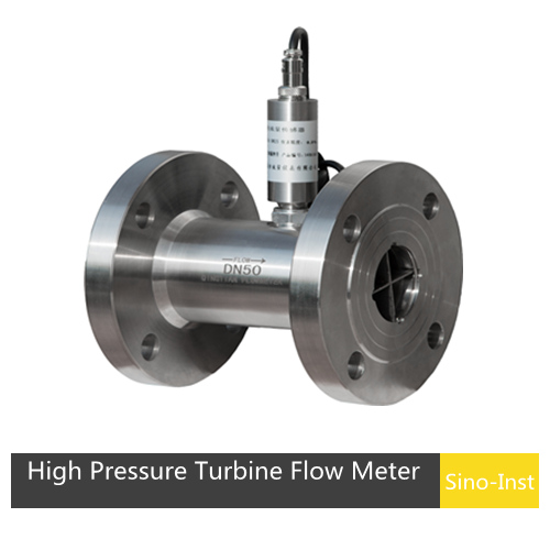
High Pressure Flow Meter
SI-3206 High Pressure Turbine Flow Meter
Sino-Inst manufactures flow meters for various pressure requirements. High pressure flow meters typically refer to high pressure turbine flow meters. The SI-3206 High Pressure Turbine Flow Meter is ideal for measuring fluid flow under high pressure, such as in hydraulic testing and chemical injection systems. It withstands pressures up to 20,000 psi and is available in flow ranges from 0.08 to 32 gallons/minute.
Parameter
Value
Diameter
DN200–DN3000 mm
Accuracy
0.5% to 2.0% of reading
Temp. Range
-20–+150°C
Pressure
40 MPa
Flow Rate
0.5–6 m/s
Straight Pipe
Upstream ≥5DN, Downstream ≥3DN
Low Pressure Flow Meter
For low pressure and low flow rate applications, thermal mass flow meters are typically used. The SI-3503 Gas Mass Flow Meter is a flange-type pipe thermal mass flow meter that provides direct mass or standard volumetric flow measurement for gas or air.
Best Technology Guide to Thermal Mass Flow Meters. A thermal mass flowmeter (TMF) is a gas flowmeter designed based on the principles of thermal diffusion or heat conduction. It directly measures the mass flow of gas without the need for…
Compared with traditional contact torque sensors, Contactless Torque Sensor avoids physical contact. This feature significantly reduces wear and energy loss. Improves the reliability of the measurement system. Contactless Torque Sensor does not mean that the sensor can obtain measurement results…
Best Technology Guide to Ultrasonic Flow Meters. An ultrasonic flow meter is a volumetric flow meter that measures the flow rate of a medium based on the effect of the flowing medium on the ultrasonic velocity or ultrasonic pulse. There…
Flow meters measure the volume or mass of liquid, gas, or steam moving through a piping system. There are many different flow meter technologies, and each delivers different accuracy. The accuracy requirements for a flow meter depend a great deal…
Coriolis Mass Flow Meter — Working Principle, Installation & Price. A Coriolis mass flow meter reads the Coriolis effect to measure mass flow directly — the same physics a fuel depot uses to prove a tanker’s load or a chemical…
A turbine flow meter is a volume flowmeter that uses the mechanical energy of the liquid or gas to rotate a rotor in the flow stream. The velocity of the turbine rotor is proportional to the velocity of the fluid…
Zhang Wei, possesses 20 years of experience as an automation instrumentation engineer, specializing in the research, design, installation, commissioning, and maintenance of automation instruments.
Face to various instrument communication protocols (such as Modbus, Profibus, etc.), with solid hardware circuit design and software programming skills (proficient in C language and PLC programming). Has extensive project experience; projects he has led and participated in have all achieved outstanding results, improving product accuracy, reducing costs, and increasing production efficiency.
Possesses excellent communication and coordination skills and a strong team spirit, enabling him to quickly respond to customer needs and provide high-quality automation instrumentation solutions.