Home > Technologies > Magnetic Flow Meter: Working Principle, Installation & Calibration Guide
Magnetic Flow Meter: Working Principle, Installation & Calibration Guide
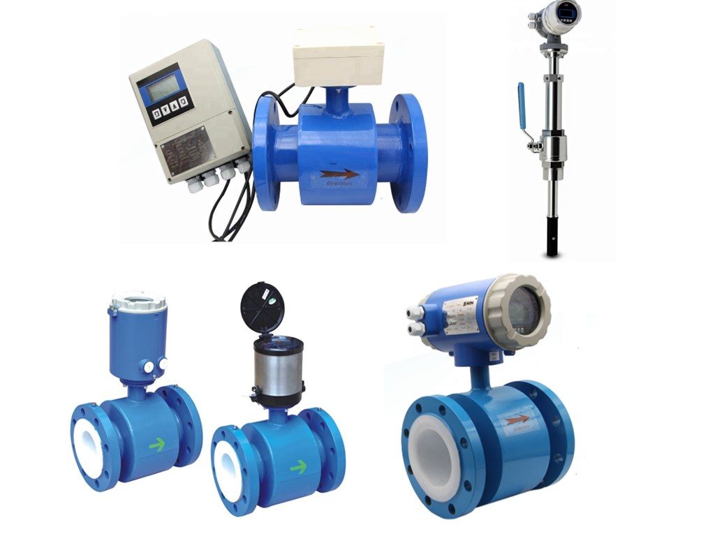
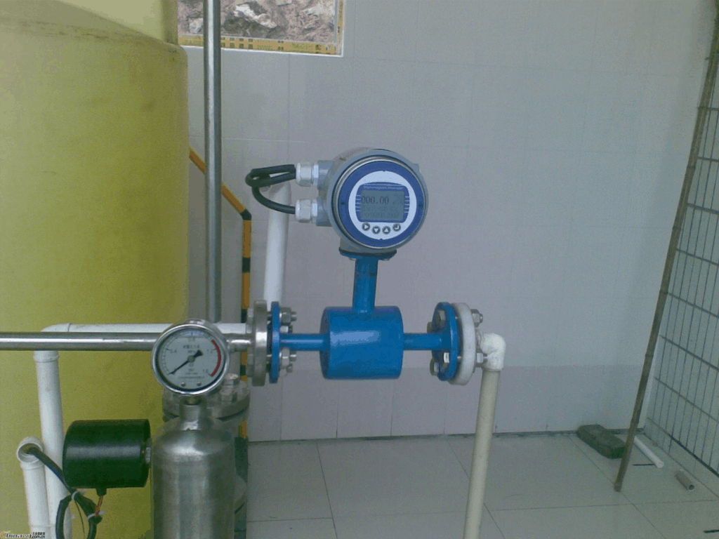
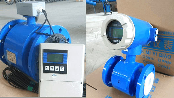
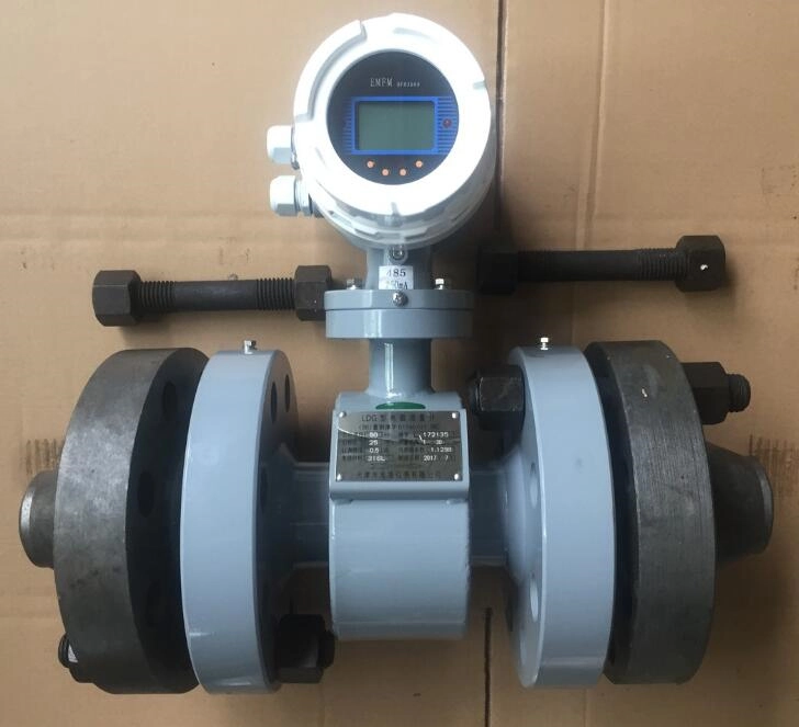
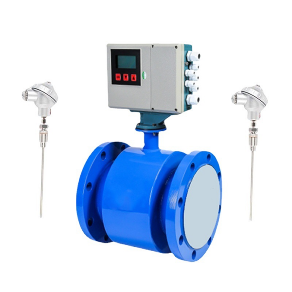
A Magnetic flow meter, also called electromagnetic flow meter, mag flow meter, or magmeters. A magnetic flow meter is a volumetric flow meter that works with principle of magnetic technology. Magnetic flow meters do not have any moving parts. An electromagnetic flowmeter consists of two parts: Electrode (sensor) and Transmitter.
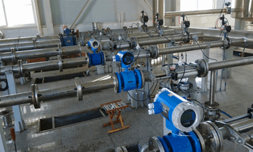
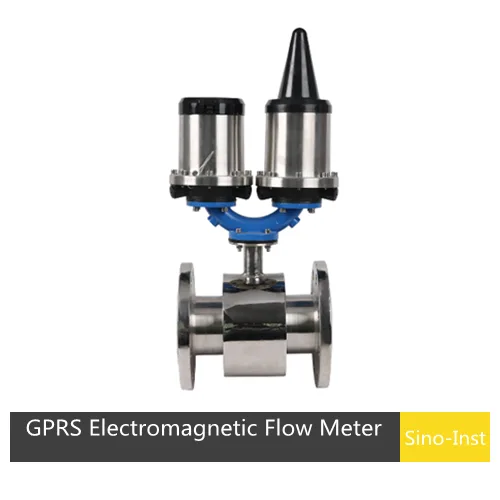
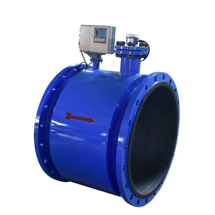
Installation types of magmeters could be: Compact, remote, insertion. Magnetic flow meter is ideal for wastewater applications or any dirty liquid which is conductive or water based. Here, we’ll take a detailed look at magnetic flowmeter technology.
An electromagnetic flowmeter uses the principle of electromagnetic induction to measure the flow rate of conductive fluids. When a conductive liquid passes through an external magnetic field, an electromotive force (EMF) is induced proportional to the flow velocity. The main components of an electromagnetic flowmeter include the magnetic circuit system, measurement conduit, electrodes, housing, lining, and converter.
During measurement, the excitation coil in the sensor generates a magnetic field. As the conductive fluid passes through this field, it cuts through the magnetic field lines, producing a small induced electromotive force (EMF). The electrodes collect this EMF signal and transmit it to the converter, which amplifies and processes the signal. The converter then calculates the corresponding flow rate using a mathematical formula, and displays the result on the meter or outputs it to a host control system.
What Are the Key Features of a Magnetic Flow Meter?
1. Measurement not affected by changes in fluid density, viscosity, temperature, pressure and conductivity;
2. No obstructing flow parts in the measuring tube. No pressure loss, and the requirements for straight pipe sections are low. Unique adaptability to slurry measurement;
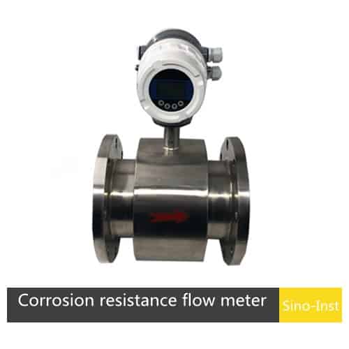
3. Reasonable selection of sensor lining and electrode material. So magmeter has good corrosion resistance and wear resistance;
4. The converter uses a novel excitation method, low power consumption, stable zero point and high accuracy. Flow range can reach 150: 1;
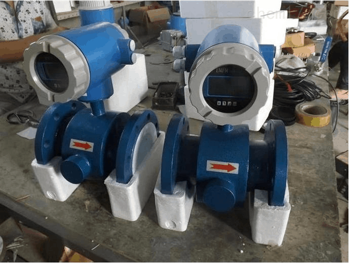
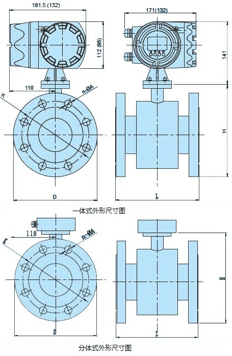
5. The converter can be integrated or separated with the sensor;
6. The converter uses a 16-bit high-performance microprocessor. 2×16 LCD display, convenient parameter setting and reliable programming;
7. The flow meter is a two-way measurement system. With three totalizers built in: forward total, reverse total, and difference total. It can display positive and reverse flow and has multiple outputs: current, pulse, digital communication , HART;
8. The converter uses surface mount technology (SMT), with self-checking and self-diagnostic functions;
9. Accuracy not affected by changes in fluid density, viscosity, temperature, pressure, and conductivity.
10. No obstruction in the measuring pipe. No additional pressure loss. No moving parts in the measuring pipe. Life of the sensor is long.
11. The induced voltage signal is formed in the entire magnetic field-filled space. And the voltage signal is the average value on the pipe loading surface. The straight pipe section required by the sensor is shorter and the pipe diameter is 5 times the length.
12. Adopts the most advanced single-chip microcomputer (MCU) and surface mount technology (SMT). Reliable performance. High accuracy. Low power consumption, Stable zero point, and convenient parameter setting. Display the accumulated flow, instantaneous flow, flow rate, flow percentage, etc.
13. Two-way measurement system can measure forward flow and reverse flow.
What Are the Advantages and Disadvantages?
Advantages of Electromagnetic Flowmeter
The range of the electromagnetic flowmeter is extremely wide. The output is only proportional to the average flow velocity of the measured medium. And the flow state (laminar or turbulent) in a symmetrical distribution has no no effect. So, and its measurement range is up to 100: 1, and some even reach the operational flow range of 1000: 1.
No obstructing flow parts in the measuring tube of the electromagnetic flowmeter. And the straight straight pipe section requirements are relatively low.
The structure of the sensor of the electromagnetic flowmeter is simple. There are no or any throttling parts in the measuring tube that hinder fluid flow. So, it will not cause any extra pressure loss when the fluid passes through the flow meter. And it is one of the flow meters with low energy consumption.
The electromagnetic flowmeter has no mechanical inertia and has a more sensitive response. It can measure the instantaneous pulsating flow, and the flow in both directions.
The electromagnetic flowmeter is a volume flow measuring instrument. During the measurement process, it is not affected by the temperature, viscosity, conductivity (within a certain range) and density of the measured medium. So, the electromagnetic flowmeter can measure the flow rate of other conductive liquids with ease only after water calibration.
The caliber of electromagnetic flowmeters is wide, from a few millimeters to several meters. And China already has real-flow calibration equipment with a caliber of 3m. Laying the foundation for the use and development of electromagnetic flowmeters.
It can measure the flow of dirty media, corrosive media and suspended liquid-solid two-way flow. There are no moving parts inside the measuring tube. And only the measuring tube lining and electrodes that touch the measured fluid. Materials of lining and electrodes can be selected according to the properties of the measured fluid. For example, using polytrifluoroethylene or polytetrafluoroethylene as the inner lining can measure various corrosive media. Such as acids, alkalis, and salts. Using abrasion-resistant rubber as the inner lining. Suitable for measuring solid particles with large abrasion Liquid-solid two-way flow of mineral pulp, cement slurry and various suspended liquids. Such as fiber-containing liquid and pulp.
Disadvantages of Electromagnetic Flowmeter
Do not measure gases, vapors, and liquids containing large amounts of gas.
It cannot be used to measure liquids with low conductivity or non-conductivity. Such as petroleum products or organic solvents. At present, electromagnetic flowmeters are powerless.
Will be affected by the surrounding strong magnetic field.
Cannot be used to measure high temperature media. Limited by the lining material and materials of the measuring tube of the electromagnetic flowmeter.
How does a magnetic flow meter work?
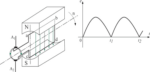
Magnetic flow meters use the principle of Faraday’s Law of Electromagnetic Induction to measure the flow rate of liquid in a pipe. In the magnetic flowmeter pipe parts, a magnetic field is generated, and channeled into the liquid flowing through the pipe. Faraday’s Law states that the voltage generated is proportional to the movement of the flowing liquid. A conductor moving through a magnetic field produces an electric signal within the conductor.
The signal voltage is proportional to the velocity of the fluid moving through the magnetic field. As the conductive liquid flows past the electrodes, changes in the induced voltage are detected. This variation is used to calculate the flow velocity through the pipe. When the fluid moves faster, more voltage is generated. The electronic transmitter then processes the voltage signal to determine the liquid flow rate.
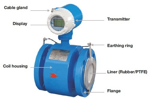
Magnetic Flow Meter Construction and Components
The electromagnetic flowmeter consists of six key components: a magnetic circuit system, a measurement conduit, electrodes, a housing, a lining, and a converter (transmitter). Magnetic Circuit System: Generates a uniform DC or AC magnetic field across the measurement area. Measurement Conduit: Allows the conductive liquid to pass through the sensing zone. Electrodes: Detect the induced potential signal, which is proportional to the flow velocity.
Housing: Made of ferromagnetic material, the housing serves as the outer cover of the excitation coil assembly and shields the system from external magnetic field interference. Lining: Applied to the inside of the measurement tube and the flange sealing surface, the lining provides a continuous layer of electrical insulation. It protects the tube from corrosion and prevents the induced potential from being short-circuited by the metal tube wall. Common lining materials include PTFE (polytetrafluoroethylene) and ceramic.
These lining materials are selected for their resistance to corrosion, high temperatures, and abrasive wear. Converter (Transmitter): Converts the induced potential signal detected by the electrodes into a standardized DC output signal, typically 4-20 mA, for integration with control systems.
What Is the Minimum Conductivity for a Magnetic Flow Meter?
Most magnetic flow meters require a minimum fluid conductivity of 5 µS/cm (5 × 10⁻⁶ S/cm). Some manufacturers rate their meters down to 1 µS/cm, but accuracy degrades as conductivity approaches the threshold. Deionized water (typically 0.1–1 µS/cm) and pure hydrocarbons (non-conductive) cannot be measured with a standard mag meter.
The measurement principle depends on the liquid carrying enough charge to generate a detectable signal voltage. Below the conductivity threshold, the signal-to-noise ratio drops sharply, causing erratic readings or zero output. Keep in mind that conductivity also varies with temperature — hot fluids tend to be more conductive than cold ones.
The table below lists typical conductivity values for common industrial fluids. Anything above 5 µS/cm is measurable with a standard magnetic flow meter.
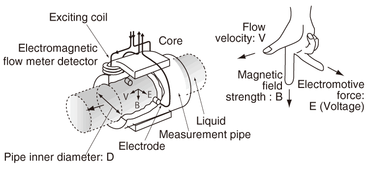
A magmeter utilizes a set of coils and a pair of electrodes for flow measurement. The meter’s coils are driven by the transmitter with an applied current. Once powered, a magnetic field is formed between both coils. When the pipe is full and the fluid begins to flow, the force of the magnetic field causes the negatively and positively charged particles of the fluid to separate as they pass through the magnetic field. This separation causes an induced voltage between the electrodes and sensor.
What is the principle of magnetic flow meter?
The operating principle of a magnetic flow meter is based on Faraday’s Law of Electromagnetic Induction. Faraday’s Law states that the voltage generated across a conductor moving through a magnetic field is proportional to the velocity of that conductor. In a magnetic flow meter, the conductive fluid serves as the moving conductor. The transmitter processes this voltage signal to determine the liquid flow rate. The following video provides a clear visual explanation of this principle:
Faraday’s Formula
Faraday’s Formula
E is proportional to V x B x D, where:
E = The voltage generated in the conductor V = The velocity of the conductor B = The magnetic field strength D = The length of the conductor
To apply this principle to flow measurement, the fluid being measured must be electrically conductive for Faraday’s Law to apply.
As applied to magnetic flow meter design, Faraday’s Law indicates that the signal voltage (E) depends on three variables:
V = The average liquid velocity B = The magnetic field strength D = The distance between the electrodes (which serves as the conductor length)
Electromagnetic Flow Meter Design
For a deeper technical exploration of electromagnetic flowmeter design, including circuit architecture and signal processing, refer to this comprehensive resource: Electromagnetic Flow Meters: Design Considerations and Solutions. It covers system design approaches that improve performance while reducing cost and power consumption.
What is a mag meter used for?
In a magnetic flow meter, the only parts in contact with the measured fluid are the liner and electrodes. Both of these wetted components can be manufactured from corrosion-resistant materials, enabling magnetic flow meters to handle a wide range of corrosive liquids and abrasive slurries.
Additionally, the liner and electrode materials can be selected to avoid contaminating the process fluid, making magnetic flow meters well suited for sanitary and hygienic applications.
Dirty liquids
Highly corrosive liquids
Slurry
Liquid is feed using gravity
Vacuum service
Dirty liquid applications are commonly found in the water, wastewater, mining, mineral processing, power, pulp and paper, and chemical industries. With proper attention to materials of construction, magnetic flow meters can accurately measure highly corrosive liquids (such as acids and caustics) as well as abrasive slurries. Corrosive liquid applications are most commonly found in chemical industry processes and in the chemical feed systems used across many industries.
Slurry applications are commonly found in the mining, mineral processing, and wastewater industries. For slurry service, size the magnetic flow meter to operate above the velocity at which solids settle (typically 1.5 to 2 ft/sec) to avoid filling the pipe with solids that can affect measurement accuracy and potentially block the flow. Magnetic flow meters are also often used where the liquid is gravity-fed. In these installations, ensure the flow meter orientation keeps it completely filled with liquid, as a partially filled pipe will affect measurement accuracy. Use extra caution when operating magnetic flow meters in vacuum service, because certain liner materials can collapse and be drawn into the pipeline. Note that vacuum conditions can occur even in pipes that may not appear to be exposed to vacuum service.
This includes pipes in which gas can condense, often under abnormal conditions. Similarly, excessive temperature exposure in magnetic flow meters, even briefly during abnormal conditions, can result in permanent damage to the instrument.
How Do You Use a Magnetic Flow Meter?
Which Industries Use Magnetic Flow Meters?
Magnetic flow meters are well suited for a variety of applications across a range of industries including: Pulp and paper;Metals and mining;Water and wastewater;Food and beverage;Chemical;Petrochemical;Oil and gas.
What Are the Typical Applications?
Thanks to their corrosion-resistant construction, magnetic flow meters are widely used across industries that handle aggressive or contaminated fluids. Typical applications include water and wastewater treatment, chemical processing, mining and mineral processing, pulp and paper production, and food and beverage manufacturing. In each of these industries, the ability to measure flow without obstructing the pipeline or introducing moving parts provides significant advantages in terms of reliability and maintenance.
Magnetic flow meters are also ideal for sanitary applications where contamination-free measurement is critical, such as in pharmaceutical and food-grade processes.
To prevent solids from accumulating in the pipe and affecting measurement accuracy, size the magnetic flow meter to operate above the velocity at which solids settle (typically 1.5 to 2 ft/sec). For abrasive service, magnetic flow meters are usually sized to operate at lower velocities (below 5 to 6 ft/sec) to reduce wear, while still remaining above the settling velocity despite the trade-off in increased wear. These considerations may change the required flow meter range, so the meter size may differ from what would be selected for an equivalent flow of clean water.
Water Flow Meter Types — Water flow meters are instruments designed to measure and display the flow rate of water. Accurate water flow measurement is essential for industrial applications such as wastewater treatment.
The main types of water flow meters include electromagnetic (magnetic), turbine, ultrasonic, and differential pressure (DP) meters. Coriolis and oval gear flow meters can also be used for water flow measurement. These meters are available with digital displays, battery power, and analog or pulse output options, in materials such as 316 stainless steel or special alloys.
Wastewater Flow Meter — Wastewater flow meters are designed for water and wastewater treatment applications. Electromagnetic flow meters are the most commonly used type due to their ability to handle dirty, conductive fluids with no pressure drop.
Ultrasonic flow meters are another viable option, especially when modifying existing piping is not feasible.
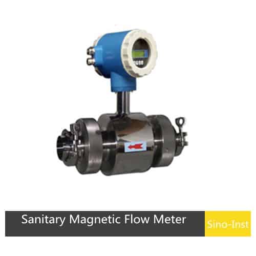
Sanitary Flow Meter — Also known as the tri-clamp flow meter, sanitary flow meters are specifically designed for hygienic applications in the food, beverage, and pharmaceutical industries, where product purity must be maintained.
Sino-Inst’s magnetic and turbine flow meters are available in sanitary configurations with tri-clamp connections, meeting the strict hygiene standards required for food-grade and pharmaceutical processing.
What Are the Application Limits of Magnetic Flow Meters?
1. Do not operate a magnetic flowmeter near its electrical conductivity limit. Because the flowmeter can turn off.
2. Provide an allowance for changing composition and operating conditions. This can change the electrical conductivity of the liquid.
3. In typical applications, magnetic flowmeters are sized. So that the velocity at maximum flow is approximately 2-3 meters per second.
4. Gravity fed pipes may require a larger magnetic flowmeter to reduce the pressure drop. So as to allow the required amount of liquid to pass through the magnetic flowmeter without backing up the piping system. Operating at the same flow rate in the larger flowmeter will result in a lower liquid velocity as compared to the smaller flowmeter.
5. For slurry service, be sure to size magnetic flowmeters to operate above the velocity at which solids settle (typically 1 ft/sec). To avoid filling the pipe with solids that can affect the measurement and potentially stop flow.
6. Magnetic flowmeters for abrasive service are usually sized to operate at low velocity (typically below 3 ft/sec) to reduce wear.
How to Troubleshoot a Magnetic Flow Meter
After the flowmeter is put into operation, or after a period of normal use, if you notice that the instrument is not working properly, first check the common troubleshooting items below before concluding the flow sensor itself is at fault. Identify which category the symptom falls into, then follow the corresponding diagnostic steps. Common fault types include:
No flow output
Check whether the power supply part is faulty.
Test whether the power supply voltage is normal.
Test whether the fuse is on or off.
Check whether the arrow of the sensor is consistent with the fluid flow direction. Such as inconsistently changing the sensor installation direction.
Check whether the sensor is full of fluid, if not full of fluid, replace the pipe or install vertically.
The signal is getting smaller or abrupt
Test whether the insulation between the two electrodes is damaged or shorted.
The resistance between the two electrodes is normally between (70 ~ 100) Ω; dirt may be deposited on the inner wall of the measuring tube.
The electrodes should be cleaned and wiped, and the inner lining should not be scratched.
Measure the pipe lining for damage and replace it if damaged.
The zero point is unstable
Check whether the medium is full of measuring tubes and whether there are air bubbles in the medium.
If there are air bubbles, install a deaerator upstream. If the installation is horizontal, change to a vertical installation.
Check whether the grounding of the instrument is intact. Perform three-level grounding (grounding resistance ≤100Ω).
Check that the dielectric conductivity is not less than 5 μs / cm.
Check whether the medium is deposited in the measuring tube, and be careful not to scratch the inner lining when removing it.
The flow indication value does not match the actual value
Check whether the fluid in the sensor is full of tubes and whether there are air bubbles. If there are air bubbles, install a deaerator upstream.
Check whether the grounding is good.
Check whether there is a valve upstream of the flow meter.
Check the converter range setting is correct, if not, set the correct range again.
The displayed value fluctuates in a certain interval
Check whether the environmental conditions have changed. If there are new interference sources and other magnetic sources or vibrations that affect the normal operation of the instrument, the interference should be removed in time or the flow meter should be removed. Test signal cables should be treated with insulating tape for end treatment.
The wires, the inner shield, the outer shield, and the shell do not touch each other.
How Accurate Is a Magnetic Flow Meter?
A standard industrial magnetic flow meter achieves ±0.5% of reading accuracy. High-performance models reach ±0.2% of reading, and some custody-transfer units are rated at ±0.15%. These figures apply within the specified flow-velocity range — typically 0.3 m/s to 10 m/s. Below 0.3 m/s, accuracy degrades because the induced signal voltage becomes very small relative to electrical noise.
Typical magnetic flow meter specifications: Accuracy: ±0.5% of reading (standard), ±0.2% (high-performance) Repeatability: ±0.1% Flow velocity range: 0.3–10 m/s Turndown ratio: 30:1 to 100:1 Process pressure: up to 40 bar (standard flanged), higher with custom housings Process temperature: −40 °C to +180 °C (PTFE lining), up to +350 °C (ceramic lining) Electrode materials: 316L SS, Hastelloy C, Tantalum, Platinum Liner materials: PTFE, PFA, rubber (neoprene/EPDM), ceramic Output: 4–20 mA, HART, Modbus RS485, pulse/frequency Protection rating: IP65 / IP67 / IP68
How do you install a magnetic flow meter?
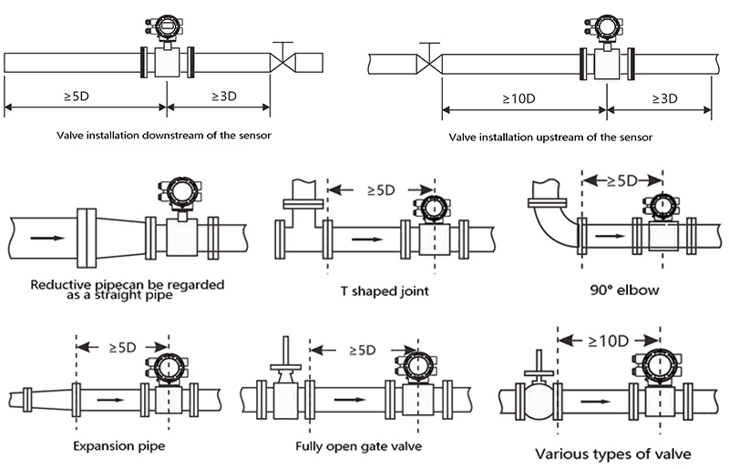
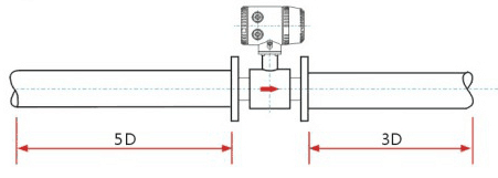
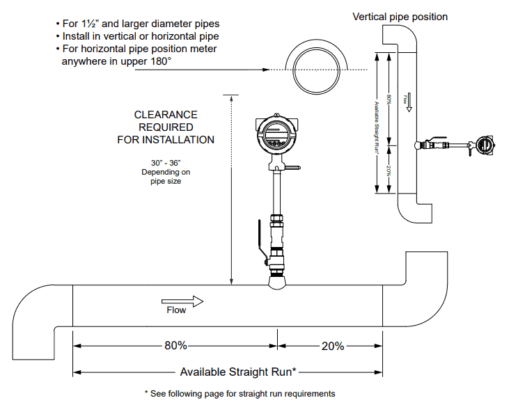
An electromagnetic flowmeter consists of a flow sensor and a transmitter. It should be installed at the lowest point of the pipeline or on a vertical section to ensure the pipe remains completely full of liquid. A minimum of 5 pipe diameters (5D) of straight pipe upstream and 3 pipe diameters (3D) downstream is required to achieve accurate measurements. The measurement principle of a magnetic flowmeter does not depend on the flow profile characteristics.
Some standards recommend 10D upstream and 3D downstream (though 5D/2D is commonly accepted). It has even been suggested that the flow sensor be factory-calibrated together with its upstream and downstream straight-pipe spools on a flow-calibration rig, reducing uncertainty caused by field installation variations. When comparing different models, do not focus solely on stated accuracy — review the manufacturer’s documentation for the full set of installation requirements and performance conditions.
Turbulence and swirl generated in non-measurement zones — for example by elbows, partially open valves, or tangential inlets upstream — do not affect accuracy as long as the flow profile has stabilized before reaching the sensor. However, if a steady-state swirl persists within the measurement area itself, both stability and accuracy will suffer. In such cases, consider the following remedies:
1. Increase the length of the upstream and downstream straight-pipe sections. 2. Install a flow conditioner or straightening vane. 3. Reduce the pipe cross-section at the measurement point to accelerate the flow and suppress swirl.
Straight Run Requirements by Upstream Fitting
The required upstream straight-pipe length depends on the type of disturbance. The table below lists recommended minimum distances (in pipe diameters, D) for common upstream fittings. Downstream, 3D to 5D is sufficient in all cases.
Upstream Fitting
Minimum Upstream (D)
Minimum Downstream (D)
90° elbow (single)
5
3
Two 90° elbows in same plane
10
3
Two 90° elbows in different planes
10
5
Reducer / expander
5
3
Fully open gate valve
5
3
Partially open butterfly valve
15
5
Control valve / globe valve
15
5
Pump outlet
10
5
What Are the Installation Requirements?
1. Requirements for the external environment
1.1 Do not install the flowmeter where ambient temperature fluctuates sharply or where the instrument is exposed to intense radiant heat. If such a location is unavoidable, provide thermal insulation and adequate ventilation.
1.2 Indoor installation is preferred. If the flowmeter must be mounted outdoors, protect it from direct rainfall, flooding, and prolonged sun exposure by providing a weather-proof enclosure or sunshade.
1.3 The flowmeter should be located in an environment free of corrosive gases. Where this is not possible, ensure adequate ventilation around the instrument.
1.4 Allow sufficient clearance around the flowmeter for convenient installation, wiring, and future maintenance access.
1.5 Keep the flowmeter away from strong magnetic fields and significant vibration sources. If the pipeline itself vibrates, install fixed pipe supports on both sides of the meter to dampen transmitted vibration.
2. Straight-Pipe Requirements To minimize the effects of swirl and flow-profile distortion, a defined length of straight pipe must be maintained upstream and downstream of the flowmeter.
Insufficient straight-pipe length will degrade measurement accuracy.
3. Process-Pipe Requirements The upstream and downstream piping must meet specific dimensional tolerances relative to the sensor bore:
a. The inner diameter of the adjacent process pipe (D) must satisfy 0.98 DN ≤ D ≤ 1.05 DN, where DN is the sensor’s nominal bore. b. The process pipe and sensor must be concentric; the coaxial misalignment must not exceed 0.05 DN.
4. Bypass-Pipe Requirements
Installing a bypass line around the flowmeter is strongly recommended. A bypass allows the process fluid to continue flowing while the meter is removed for maintenance or cleaning. A bypass is essential when:
a. The flowmeter requires periodic cleaning due to heavily contaminated fluid. b. The process cannot be shut down during meter servicing. c. Convenient access is needed for routine maintenance without interrupting production.
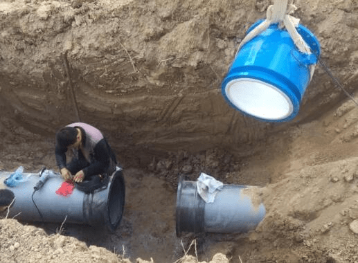
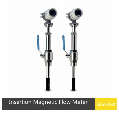
5. Installation Requirements for Insertion Magnetic Flowmeters
5.1 Straight-pipe requirements: maintain at least 10 × DN of straight pipe upstream and 5 × DN downstream of the insertion probe.
5.2 Grounding requirements: for reliable operation and accurate measurement, the sensor must be properly grounded to avoid interference from external parasitic potentials. The grounding resistance should be less than 10 Ω. Refer to the manufacturer’s grounding diagram for specific connection details.
5.3 Location requirements: install the insertion probe at the recommended position as shown in the manufacturer’s installation diagram.
General Installation Precautions
Choose a location free from strong vibration and powerful electromagnetic fields (e.g., large motors or variable-frequency drives).
Vertical installation is preferred. If the meter must be mounted horizontally, install it at a low point in the piping — never at the pipe apex — to ensure the pipe remains full and to prevent air-bubble accumulation.
Maintain adequate straight-pipe runs: at least 10 × DN upstream and 5 × DN downstream.
During pipe welding, disconnect the flowmeter from the piping to prevent heat or current damage to the instrument.
Ground the instrument housing properly. Route the signal cable’s shield to ground at one end only, and do not share the grounding point with power cables.
Select an installation location that allows convenient maintenance access. Consider adding a bypass line so process flow can continue if the meter needs to be removed.
Protect the meter from direct sunlight and extreme temperatures. Use a sunshade or insulation where necessary.
Mount the meter on a stable, rigid pipe section. If the pipeline is subject to vibration, install pipe supports on both sides of the flowmeter.
Grounding requirements
The grounding of the electromagnetic flowmeter is very important. For the sensor to work properly, it must have a good separate ground wire. The copper core area is 16mm2, and the grounding resistance is <100Ω. 1. If the pipeline connected to the electromagnetic flowmeter is insulated. A grounding ring of the same material as the electrode material should be selected. If a medium with abrasive properties is measured, a grounding ring with a neck should be selected. 2.
When the electromagnetic flowmeter is installed in plastic pipes or pipes with insulating coating or lining on the inner wall. Grounding rings must be installed at both ends of the flowmeter. If a multi-motor structure is used, the grounding ring may not be used. 3. The electromagnetic flowmeter is installed on the cathodic protection pipeline. Pay attention to that the grounding ring and the flange on the pipeline should be insulated. Because the electrolytic corrosion protection pipeline is generally insulated on its inner and outer walls.
Why does a magnetic flow meter need grounding?
The electromagnetic flowmeter signal is weak, only 2.5~8mv at full scale. Only a few microvolts when the flow rate is very small, and slight disturbance will affect the measurement accuracy.So, the transmitter casing, shielded wire, measuring conduit and transmitter of the pipes.
They must be grounded, and the grounding points should be set separately. They must not be connected to common ground lines such as motors and electrical appliances or to the upper and lower water pipes.The converter part has been grounded through the cable, so do not ground again to avoid interference caused by different ground potentials.
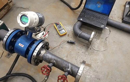
How Do You Calibrate a Magnetic Flow Meter?
Quick calibration of electromagnetic flowmeter:
1. Select the corresponding pump according to the diameter and flow rate of the pipeline for the verification test;
2. After the flowmeter is correctly installed and connected, it should be powered on and warmed up for about 30min. According to the requirements of the verification regulations;
3. If a high-level trough water source is used, check whether the overflow signal of the stabilized water tower appears. Before the formal test, according to the requirements of the verification regulations. Use the verification medium to circulate in the piping system for a certain period of time. And at the same time check whether there are leaks in the sealed parts of the piping;
4. Before starting the formal verification, the verification medium should be filled with the sensor of the flowmeter under test. And then the downstream valve should be closed for zero adjustment;
5. At the start of the inspection, the valve at the front of the pipeline should be opened first. And the valve behind the flowmeter to be inspected should be slowly opened to adjust the flow at the verification point;
6.During the calibration process, the flow stability of each flow point should be within 1% to 2%-the flow method, and the total amount can be within 5%. The temperature change should not exceed 1°C. When completing the verification process at one flow point, and should not exceed 5 ° C when completing the verification process;
7. After each test, the valve at the front of the test pipeline should be closed first. And then the pump should be stopped to avoid emptying the voltage stabilization facilities. At the same time, the remaining verification medium in the test pipeline must be emptied. And the control system and the air compressor should be shut down.
Electromagnetic Flow Meter Diagram
How to Check and Maintain a Magnetic Flow Meter
Routine maintenance for a magnetic flowmeter is straightforward. Periodically inspect the instrument and its surroundings — remove any accumulated dust or dirt, and verify that no water or other substances have entered the housing. Check all wiring connections for integrity, and note whether any strong electromagnetic equipment or new cables have been installed nearby, as these can introduce interference. If the process medium tends to coat the electrodes or leave deposits and scale on the measuring-tube lining, schedule regular cleaning to maintain measurement accuracy.
Even when the flowmeter appears to be operating normally, periodic checks are recommended to ensure long-term accuracy and reliability. If any irregularity is detected during routine inspection, refer to the troubleshooting section above to diagnose the issue. Regular maintenance helps catch potential problems before they affect process control.
Sensor Check
Test equipment: 500 MΩ insulation-resistance tester; digital multimeter.
Step 1 — With the pipeline full of process medium, use the multimeter to measure the resistance between terminals A–C and B–C. Both readings should be relatively high. If one value is more than double the other, the corresponding electrode may have a leak.
Moisture on the outer wall of the measuring tube, or condensation inside the junction box, can affect readings.
Step 2 — With the lining dry, use the insulation-resistance tester (MΩ range) to measure A–C and B–C. Both values should exceed 200 MΩ. Then measure the resistance between electrodes A and B (they should be effectively short-circuited through the medium path). If the insulation resistance is very low, the electrode insulation has failed and the entire flowmeter should be returned to the manufacturer for repair.
If the insulation resistance has dropped but remains above 50 MΩ, and Step 1 produced normal results, moisture on the outer tube wall is the likely cause. Use a hot-air blower to dry the interior of the housing.
Step 3 — Measure the resistance between excitation-coil terminals X and Y with a multimeter. A reading above 200 Ω suggests an open circuit or poor contact in the excitation coil or its lead wires. Remove the terminal board and inspect the connections.
Step 4 — Verify that the insulation resistance between X, Y and C exceeds 200 MΩ. If it has decreased, dry the inside of the housing with hot air before re-testing.
In practice, degraded coil insulation increases measurement error and makes the output signal unstable.
Step 5 — If the sensor is confirmed faulty, contact the flowmeter manufacturer. Sensor-level faults generally cannot be resolved on site and require factory repair.
Transmitter (Converter) Check If the converter is suspected to be faulty and all external causes have been ruled out, contact the flowmeter manufacturer for support.
In most cases, the manufacturer will resolve a converter fault by replacing the main circuit board.
Magnetic Flow Meter Coil Resistance: What to Expect
The excitation coil resistance of a magnetic flow meter typically falls between 30 Ω and 200 Ω, depending on the meter size and manufacturer. A DN50 (2-inch) meter usually reads around 50–90 Ω, while larger sizes (DN200 and above) may read 100–170 Ω. Measure the resistance between terminals X and Y with the power disconnected. If the reading is significantly outside the expected range — either open-circuit (infinite) or near zero — the coil winding is damaged and the sensor must be returned for repair.
Also check the insulation resistance between the coil leads (X, Y) and the signal ground (C). This value should exceed 200 MΩ when the sensor housing is dry. If it drops below 20 MΩ, moisture has likely entered the coil housing. Dry the interior thoroughly with hot air and re-test. A coil insulation value below 2 MΩ usually means permanent insulation breakdown — the sensor needs factory repair.
Can Magnetic Flow Meters Measure Wastewater?
Wastewater flow meters are essential instruments for water and wastewater treatment plants. Electromagnetic flow meters are the preferred choice in this industry due to their robust design, lack of moving parts, and ability to measure dirty or particle-laden fluids with high accuracy.
Both ultrasonic and magnetic flow meters are inline instruments commonly used in industrial applications. Sino-Inst provides both types, delivering high accuracy, long-term stability, and a low total cost of ownership.
How to Select the Right Magnetic Flow Meter
The key questions which need to be answered before selecting a magnetic flow meter are:
Is the fluid conductive or water based?
Is the fluid or slurry abrasive?
Do you require an integral display or remote display?
Do you require an analog output?
What is the minimum and maximum flow rate for the flow meter?
What is the minimum and maximum process pressure?
What is the minimum and maximum process temperature?
Is the fluid chemically compatible with the flow meter wetted parts?
With a wide array of product offerings, Sino-Inst enables users to select the right magnetic flow meter for applications across many industries, from factory automation, food and beverage processing, and mining to municipal and wastewater treatment, and pulp and paper production.
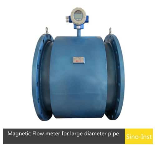
The insertion magnetic flow meter, also known as an insertion-type electromagnetic flow meter, is designed to measure the flow velocity of conductive liquids in large-diameter pipes. This style of meter is inserted directly into the pipeline through a single connection point, making it a cost-effective solution for large pipe sizes.
Insertion magnetic flow meters offer easy installation and are suitable for use with conductive fluids, including water, raw sewage, wastewater, clarified water, RAS, and WAS. Available process connections include hot-tap, DIN, and NPT thread options. The installation method should be selected based on the specific pipeline conditions.
For non-pressurized pipelines, an insertion magnetic flow meter without a ball valve can be used. The pipe opening diameter should be 50 mm, and a welded connection fitting is attached to the pipe at the insertion point.
For applications that require continuous flow or where the medium must not overflow during installation or removal, select an insertion electromagnetic flow meter with a ball valve structure. The pipe opening and welded fitting requirements are the same. The recommended operating velocity range is 0.5 to 10 m/s (continuously adjustable), with a maximum range of 0.2 to 15 m/s.
Signal output:
The switching value can be set as: pulse output (up to 1000HZ); high / low flow alarm; air pipe alarm; flow direction indication; fault alarm;
Current output: 4-20mA output
Configuration mode:
On-site configuration through three manual keys.
Field configuration via remote control.
On-site configuration through the Communicator.
How Much Does a Magnetic Flow Meter Cost?
Electromagnetic flowmeters are designed exclusively for measuring conductive media and cannot be used with non-conductive fluids. The two primary factors that influence the price of an electromagnetic flowmeter are the type of medium being measured and the pipe diameter (caliber).
Electromagnetic flowmeters are widely used for measuring clean water, sewage, various acid and alkali salt solutions, slurries, mineral pulp, paper pulp, and food-grade liquids (using sanitary-type electromagnetic flowmeters).
For example, a DN100 magnetic flowmeter for measuring acid has a reference price of approximately $495 USD per unit, while the same size meter configured for water measurement is around $400 USD per unit.
Factors affecting the price of an electromagnetic flowmeter include:
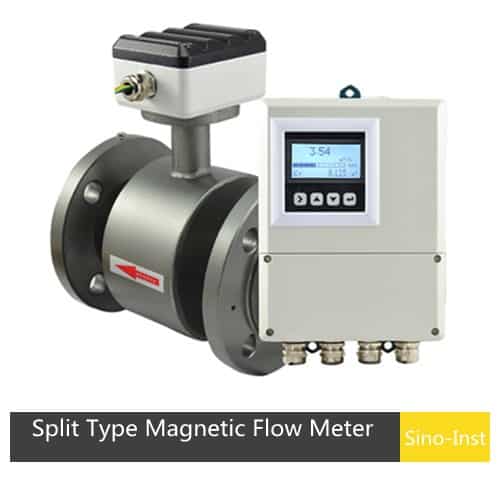
1. Structure type. Integrated (compact) and split (remote) electromagnetic flowmeters differ significantly in price due to differences in design complexity and housing.
2. Body and lining materials. The choice of body material (carbon steel, 304 stainless steel, or 316 stainless steel) and lining material (rubber, PTFE, PFA, polyurethane, etc.) directly affects cost.
3. Electrode materials. Common electrode options include stainless steel, titanium, tantalum, and platinum, each at a different price point depending on chemical compatibility requirements.
4. Connection method. Options include inline (flanged, clamped, or wafer-style) and insertion types. Each connection method involves different manufacturing costs.
5. Output signal type. The output signal format, such as pulse output or 4-20 mA analog current, can also influence the overall price.
6. Communication protocol. Communication options such as RS-485, RS-232, and HART protocol add varying levels of cost depending on the complexity of integration with existing control systems.
Who Are the Major Magnetic Flow Meter Manufacturers?
Sino-Inst is a professional flowmeter manufacturer based in China, offering over 100 flow measurement products. Approximately 30% of the product line consists of magnetic flow meters, with the remainder including turbine, vortex, ultrasonic, and mass flow meters. These instruments serve a wide range of industries, including water and wastewater treatment, chemical processing, food and beverage, oil and gas (for supporting processes), power generation, pulp and paper, metals and mining, and pharmaceutical manufacturing.
Best Technology Guide to Thermal Mass Flow Meters. A thermal mass flowmeter (TMF) is a gas flowmeter designed based on the principles of thermal diffusion or heat conduction. It directly measures the mass flow of gas without the need for…
Best Technology Guide to Ultrasonic Flow Meters. An ultrasonic flow meter is a volumetric flow meter that measures the flow rate of a medium based on the effect of the flowing medium on the ultrasonic velocity or ultrasonic pulse. There…
Coriolis Mass Flow Meter — Working Principle, Installation & Price. A Coriolis mass flow meter reads the Coriolis effect to measure mass flow directly — the same physics a fuel depot uses to prove a tanker’s load or a chemical…
Differential Pressure Flow Meters (also called DP flow meters or differential flow meters) measure flow rate by detecting the pressure drop across a restriction in the pipe. A throttling device — such as an orifice plate, Venturi tube, wedge, V-cone,…
Best Technology Guide to Vortex Flow Meters. Vortex flow meter is a kind of velocity flowmeter, based on the Karman (Von Kármán Effect designed by vortex principle research). It is mainly used for flow measurement of medium fluid in industrial…
A turbine flow meter is a volume flowmeter that uses the mechanical energy of the liquid or gas to rotate a rotor in the flow stream. The velocity of the turbine rotor is proportional to the velocity of the fluid…
Zhang Wei, possesses 20 years of experience as an automation instrumentation engineer, specializing in the research, design, installation, commissioning, and maintenance of automation instruments.
Face to various instrument communication protocols (such as Modbus, Profibus, etc.), with solid hardware circuit design and software programming skills (proficient in C language and PLC programming). Has extensive project experience; projects he has led and participated in have all achieved outstanding results, improving product accuracy, reducing costs, and increasing production efficiency.
Possesses excellent communication and coordination skills and a strong team spirit, enabling him to quickly respond to customer needs and provide high-quality automation instrumentation solutions.