
Best Technology Guide to Magnetic Flow Meters
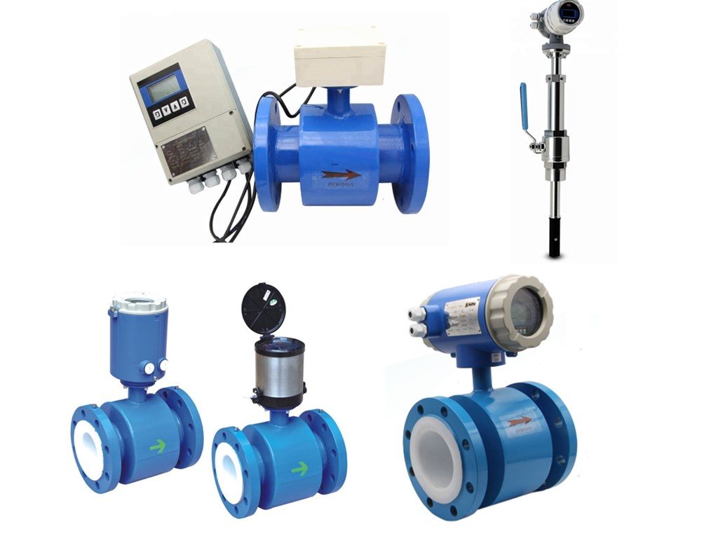
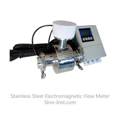
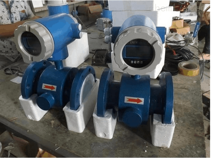
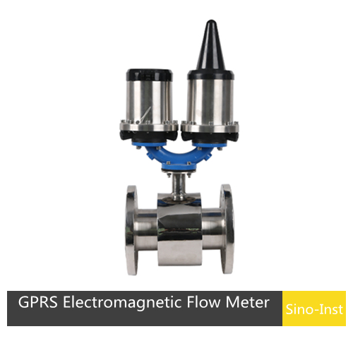
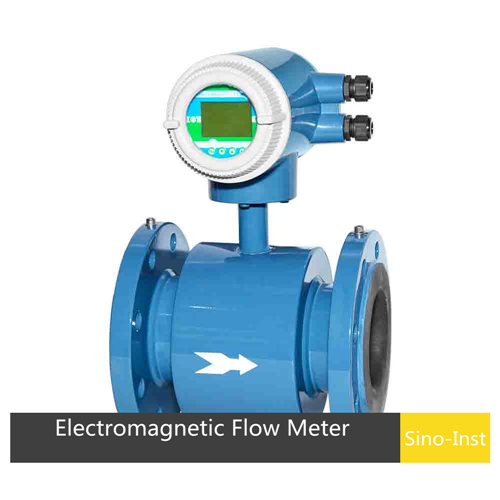
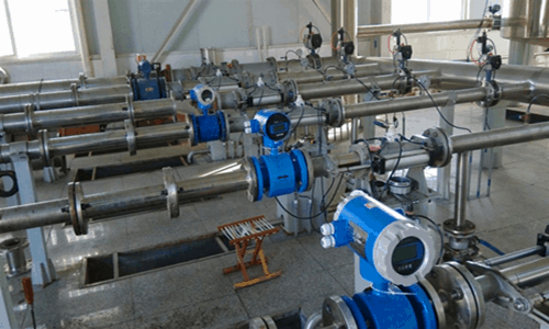
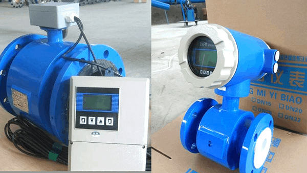
A Magnetic flow meter, also called electromagnetic flow meter, mag flow meter, or magmeters. A magnetic flow meter is a volumetric flow meter that works with principle of magnetic technology. Magnetic flow meters do not have any moving parts. An electromagnetic flowmeter consists of two parts: Electrode (sensor) and Transmitter. Installation types of magmeters could be: Compact, remote, insertion.
Magnetic flow meter is ideal for wastewater applications or any dirty liquid which is conductive or water based. Magnetic flow meters are also ideal for applications where low-pressure drop and low maintenance required. A range of liner materials, electrode options, and line sizes accommodate a wide variety of process application.
What are Electromagnetic Flow Meters?
Features of an Electromagnetic Flow Meter
- 1. Measurement not affected by changes in fluid density, viscosity, temperature, pressure and conductivity;
- 2. No obstructing flow parts in the measuring tube. No pressure loss, and the requirements for straight pipe sections are low. Unique adaptability to slurry measurement;
- 3. Reasonable selection of sensor lining and electrode material. So magmeter has good corrosion resistance and wear resistance;
- 4. The converter uses a novel excitation method, low power consumption, stable zero point and high accuracy. Flow range can reach 150: 1;
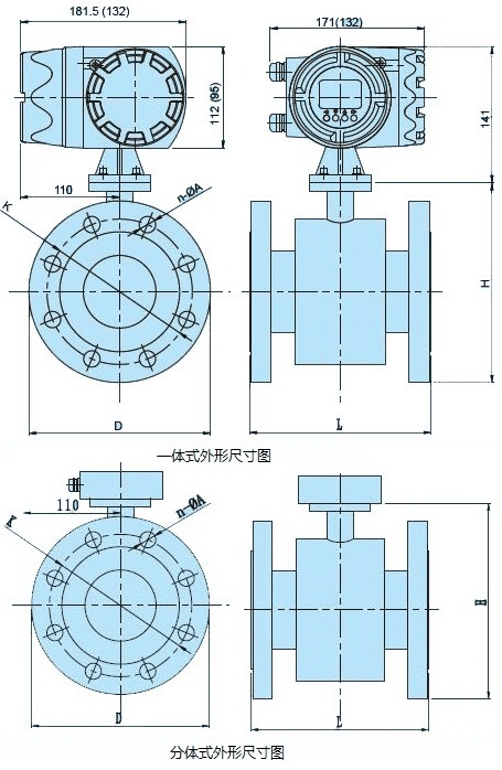
- 5. The converter can be integrated or separated with the sensor;
- 6. The converter uses a 16-bit high-performance microprocessor. 2×16 LCD display, convenient parameter setting and reliable programming;
- 7. The flow meter is a two-way measurement system. With three totalizers built in: forward total, reverse total, and difference total. It can display positive and reverse flow and has multiple outputs: current, pulse, digital communication , HART;
- 8. The converter uses surface mount technology (SMT), with self-checking and self-diagnostic functions;
- 9. Accuracy not affected by changes in fluid density, viscosity, temperature, pressure, and conductivity.
- 10. No obstruction in the measuring pipe. No additional pressure loss. No moving parts in the measuring pipe. Life of the sensor is long.
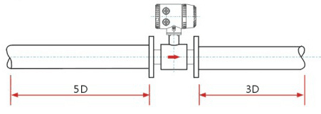
- 11. The induced voltage signal is formed in the entire magnetic field-filled space. And the voltage signal is the average value on the pipe loading surface. The straight pipe section required by the sensor is shorter and the pipe diameter is 5 times the length.
- 12. Adopts the most advanced single-chip microcomputer (MCU) and surface mount technology (SMT). Reliable performance. High accuracy. Low power consumption, Stable zero point, and convenient parameter setting. Display the accumulated flow, instantaneous flow, flow rate, flow percentage, etc.
- 13. Two-way measurement system can measure forward flow and reverse flow.
Advantages and Disadvantages
How does a magnetic flow meter work?
Magnetic flow meters use the principle of Faraday’s Law of Electromagnetic Induction to measure the flow rate of liquid in a pipe. In the magnetic flowmeter pipe parts, a magnetic field is generated, and channeled into the liquid flowing through the pipe. Faraday’s Law states that the voltage generated is proportional to the movement of the flowing liquid. A conductor moving through a magnetic field produces an electric signal within the conductor. And the singal is proportional to the velocity of the water moving through the field. As fluid flows through the magnetic field, conductive particles in the fluid create changes. This variation is used to measure and calculate the velocity of water flow through the pipe. When the fluid moves faster, more voltage is generated. The electronic transmitter processes the voltage signal to determine liquid flow.
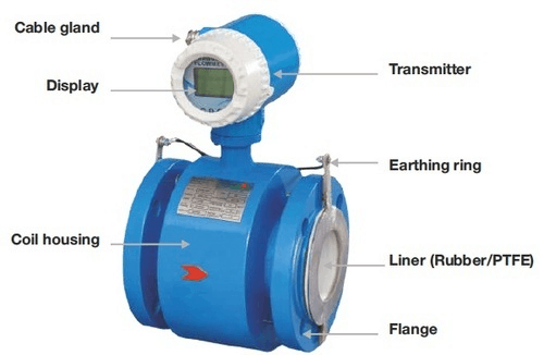
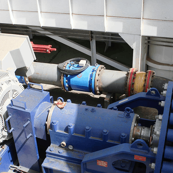
Magnetic Flow Meter Construction
Electrical Conductivity
Induced Voltage
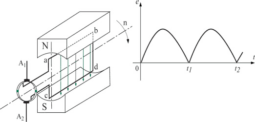
A magmeter utilizes a set of coils and a pair of electrodes for flow measurement. The meter’s coils are driven by the transmitter with an applied current. Once powered, a magnetic field is formed between both coils. When the pipe is full and the fluid begins to flow, the force of the magnetic field causes the negatively and positively charged particles of the fluid to separate as they pass through the magnetic field. This separation causes an induced voltage between the electrodes and sensor.
What is the principle of magnetic flow meter?
The operation principle of a magnetic flow meter or mag meter is based upon Faraday’s Law. Faraday’s Law states the voltage generated is proportional to the movement of the flowing liquid. The transmitter processes the voltage signal to determine liquid flow.
Rosemount explained it to us very well. Let’s take a look
Faraday's Formula
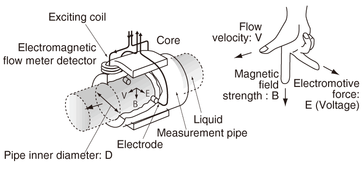
Faraday’s Formula
E is proportional to V x B x D where:
E = The voltage generated in a conductor
V = The velocity of the conductor
B = The magnetic field strength
D = The length of the conductor
Electromagnetic Flow Meter Design
Detailed research on the design of electromagnetic flowmeters. Interested users can refer to this article. Electromagnetic Flow Meters: Design Considerations and Solutions. Focuses on the design considerations of implementing an electromagnetic flowmeter architecture as a solution. That simplifies system design, improves performance, and lowers cost and power.
What is a mag meter used for?
- Dirty liquids
- Highly corrosive liquids
- Slurry
- Liquid is feed using gravity
Magnetic flowmeters are often used where the liquid is fed using gravity. Be sure that the orientation of the flowmeter is such that the flowmeter is completely filled with liquid. Failure to ensure the flowmeter is completely filled with liquid can affect the flow measurement.
- Vacuum service
How to Use Magnetic Flow meters

Industries that Use Magnetic Flow meters
Typical Applications
The only wetted parts of the magnetic flow meter are the liner and electrodes. Both the liner and electrodes can be made from materials that can withstand corrosion. The straight-through (obstruction less) nature reduces the pressure drop. And the potential for abrasion from the flowing liquid. So, magnetic flow meters can measure many corrosive liquids and abrasive slurries. Magnetic flow meter liners and electrodes can be constructed of materials that do not contaminate the liquid. So, these mag flow meters can be applied when liquid contamination is an issue, such as in sanitary applications.

Water Flow Meters are flow meters measure and show the flow rate of water flow. Water flow measurement is important for inductrial applications, like the wastewater treatment. In principle, water flow meter types are: Electromagnetic (magnetic), Turbine, Ultrasonic, and DP. Coriolis and Oval Gear flow meters can also work for water flow measurement. These water flow meters, optional with digital display, battery, analog or pulse output. Material can be 316 stainless steel or special material.
Sanitary Flow Meter, also called the tri-clamp flow meter. Sanitary Flow Meters have stainless steel bodies and come standard with Tri-Clover fittings. Sanitary flow meter meets the requirements of the food, and beverage company industries. Sino-Inst’s magnetic flowmeter and turbine flow meters is available in a sanitary version. And allows for use with Output Modules, Sensors and Remote Transmitters.
Application Cautions for Magnetic Flow meters
Magnetic Flow Mmeter Troubleshooting
After the flowmeter put into operation or after a period of normal operation, it is found that the instrument is not working properly. You should first check the external conditions of the flowmeter. Such as whether the power supply is good. Whether the pipeline is leaking or is not full. Whether there are air bubbles in the pipeline. Aand whether the signal cable Damage. Whether the output signal of the converter (that is, the input circuit of the rear instrument) is open. Do not repair the flowmeter blindly.
Check whether the power supply part is faulty.
Test whether the power supply voltage is normal.
Test whether the fuse is on or off.
Check whether the arrow of the sensor is consistent with the fluid flow direction. Such as inconsistently changing the sensor installation direction.
Check whether the sensor is full of fluid, if not full of fluid, replace the pipe or install vertically .
Test whether the insulation between the two electrodes is damaged or shorted.
The resistance between the two electrodes is normally between (70 ~ 100) Ω; dirt may be deposited on the inner wall of the measuring tube.
The electrodes should be cleaned and wiped, and the inner lining should not be scratched.
Measure the pipe lining for damage and replace it if damaged.
Check whether the medium is full of measuring tubes and whether there are air bubbles in the medium.
If there are air bubbles, install a deaerator upstream. If the installation is horizontal, change to a vertical installation.
Check whether the grounding of the instrument is intact. Perform three-level grounding (grounding resistance ≤100Ω).
Check that the dielectric conductivity is not less than 5 μs / cm.
Check whether the medium is deposited in the measuring tube, and be careful not to scratch the inner lining when removing it.
Check whether the fluid in the sensor is full of tubes and whether there are air bubbles. If there are air bubbles, install a deaerator upstream.
Check whether the grounding is good.
Check whether there is a valve upstream of the flow meter.
Check the converter range setting is correct, if not, set the correct range again.
Magnetic Flow Mmeter Accuracy
How do you install a magnetic flow meter?
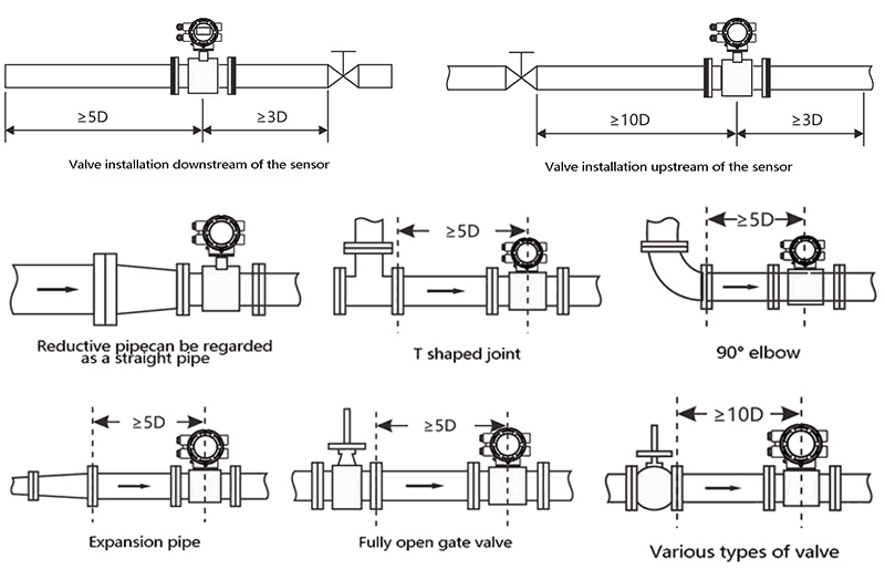
Installation Considerations
To improve the effect of eddy current and flow field distortion. The length of the front and rear straight pipe sections of the flow meter is required to be fixed. Otherwise it will affect the measurement accuracy.
The flowmeter has certain requirements on the upstream and downstream process pipes of the installation point. Otherwise it will affect the measurement accuracy.
- 1. Where there is no vibration or strong electromagnetic field (such as large motor and inverter);
- 2. As far as possible vertical installation. Horizontal installation needs to be installed in a low place. Can not install the pipe apex. Ensure full pipe. Prevent air bubbles;
- 3. Straight pipe requirements, it is best to ensure 5 times the diameter of the first 10;
- 4. When welding, please pay attention not to connect the instrument to prevent damage to the flowmeter;
- 5. The shell should be grounded as far as possible. The shielded wire should be grounded at one end, and the point can not be shared with the strong electricity;
- 6. If it is convenient for maintenance, the installation location needs to be selected to meet the maintenance requirements. At the same time, the side pipe can be installed, and the fluid moves along the side pipe when the fault occurs;
- 7. To avoid direct sunlight, high temperature, will degauss;
- 8. Other requirements should be considered, the signal wiring should not be with the strong electric line.
Grounding requirements
Why does a magnetic flow meter need grounding?
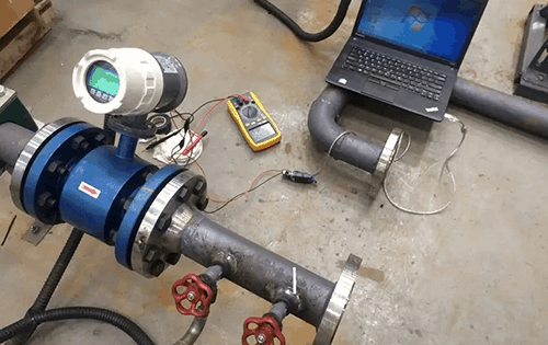
Magnetic Flow Meter Calibration
Electromagnetic Flow Meter Diagram
How to check magnetic flow meter
You only need to perform periodic visual inspection of the instrument. Check the surrounding environment of the instrument. Remove dust and dirt. Ensure that no water and other substances are ingress. Check whether the wiring is good. And check whether there are newly installed strong electromagnetic field equipment. Or newly installed wires across the instrument near the instrument. If the measurement medium easily stains the electrode or deposits or scales in the measuring tube wall. It should be cleaned and cleaned regularly.
After the flowmeter put into operation or after a period of normal operation, it is found that the instrument is not working properly. You should first check the external conditions of the flowmeter. Such as whether the power supply is good. Whether the pipeline is leaking or is not full. Whether there are air bubbles in the pipeline. And whether the signal cable Damage. Whether the output signal of the converter (that is, the input circuit of the rear instrument) is open. Remember not to repair the flowmeter blindly.
Sensor check
Magnetic Flow Meters for Wastewater
Magmeter Selection
The key questions which need to be answered before selecting a magnetic flow meter are:
- Is the fluid conductive or water based?
- Is the fluid or slurry abrasive?
- Do you require an integral display or remote display?
- Do you require an analog output?
- What is the minimum and maximum flow rate for the flow meter?
- What is the minimum and maximum process pressure?
- What is the minimum and maximum process temperature?
- Is the fluid chemically compatible with the flow meter wetted parts?
- What is the size of the pipe?
- Is the pipe always full?
Magnetic Flow Meter Options
- General purpose mag meter
- Battery-powered mag meter
- High pressure mag meter
- Mag meter with integrated BTU measurement
- Ceramic-lined mag meter
- Insertion mag meter
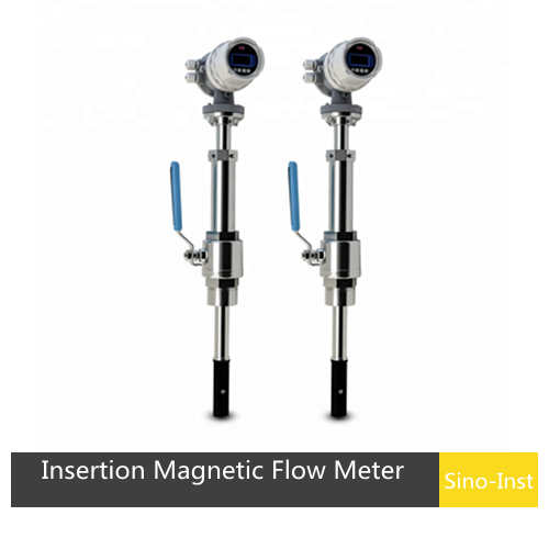
Insertion Magmeters
Insertion Magnetic Flow Meter, also called Insertion type Electromagnetic flow meter. Insertion style flow meter, measures the flow velocity of conductive liquids in large diameter pipes.
Magnetic Flow Meter Price
The closest technology to Mag that could possibly handle similar applications. More cost effectively would be vortex shedding. They can handle light particulate, have a higher pressure drop, lower rangeability and are slightly less accurate.
Magnetic Flow Meter Manufacturers
Magnetic flow meter PDF
Wu Peng, born in 1980, is a highly respected and accomplished male engineer with extensive experience in the field of automation. With over 20 years of industry experience, Wu has made significant contributions to both academia and engineering projects.
Throughout his career, Wu Peng has participated in numerous national and international engineering projects. Some of his most notable projects include the development of an intelligent control system for oil refineries, the design of a cutting-edge distributed control system for petrochemical plants, and the optimization of control algorithms for natural gas pipelines.