Orifice Plate Installation Guidelines
Orifice plate flowmeter installation requirements and precautions
Orifice plate is a standard throttling device with the most specifications. It is the simplest and most adaptable product among throttling devices. It is widely used in various fluids, especially gas flow measurement.
What’s an orifice plate?
The orifice plate only refers to the key part of the throttling device-the throttling piece. Because it is a metal plate with holes, it is named after it.
After a long time, the entire throttling device is also commonly referred to as the orifice plate, and the differential pressure flowmeter is also commonly referred to as the orifice plate.
The standard name of orifice flowmeter is throttling device, which is the most commonly used type of differential pressure flowmeter.
The throttling device is a differential pressure sensing element that measures the flow rate. It can be used to measure, integrate and control the instantaneous flow and cumulative flow of liquid, steam and gas in conjunction with a differential pressure transmitter and actual, recording, accumulating and regulating instruments.
The throttling device has a simple structure, easy installation, reliable use, low price, convenient maintenance, and a wide range of options.
The standard section device can measure the pipe diameter from 50mm to 1200mm, and the applicable pipe diameter of the non-standard throttling device can also be as small as 6mm and as large as 3000mm;
The measurement temperature can be as high as 555℃; the pressure resistance can reach 42MPa.
And the standard throttling device also has the advantages of not requiring separate calibration, and is the most widely used and most mature product in flow meters. Therefore, it is widely used in electric power, chemical industry, metallurgy, petroleum, textile, military and other fields.
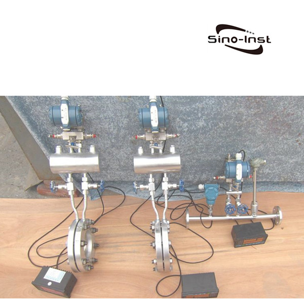
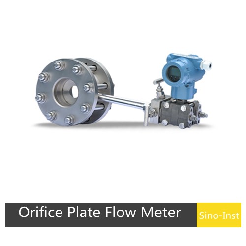
The throttling device is composed of a throttling piece, a pressure-taking device (including a pressure-taking port, a pressure-inducing pipe and a valve, etc.), a supporting flange, and sometimes also includes front and rear straight pipe sections that meet the standard.
The standard throttling device includes a standard orifice plate, a standard nozzle, and a standard venturi tube.
The standard orifice plate is divided into angle connection (annular chamber or drilling) pressure, flange pressure, and diameter pressure according to the pressure taking method;
Standard nozzles are divided into ISA1932 nozzles and long diameter nozzles according to the form;
The standard venturi tube is divided into venturi nozzle and venturi tube (rough casting or machining or coiling) according to the form.
Non-standard throttling devices include small diameter orifice, 1/4 round orifice, round orifice, round orifice, eccentric orifice, double orifice, built-in orifice, tapered inlet orifice, etc.
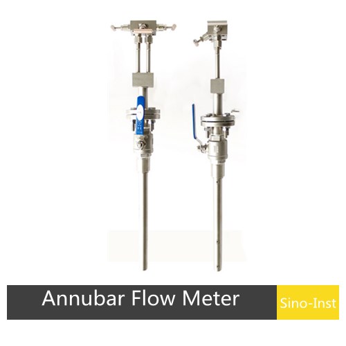
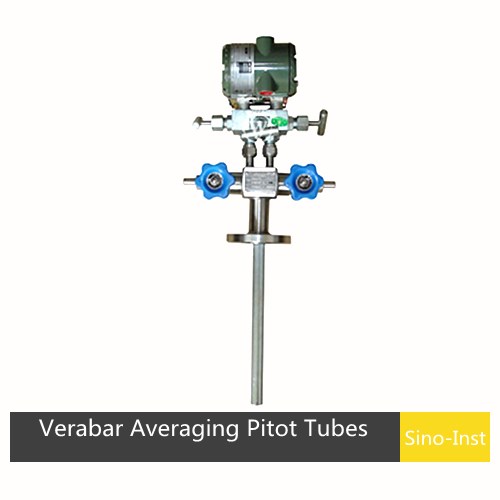
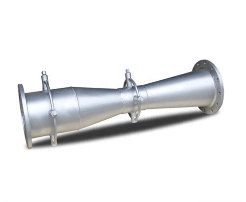
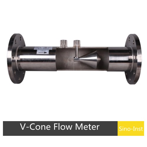
Other types of throttling devices include pitot tube, average velocity tube, wedge, cone, etc. If you need to order, please contact our company.
Orifice plate working principle
I guess most people wondered: What is the working principle of orifice meter?
As the fluid approaches the orifice the pressure increases slightly and then drops suddenly as the orifice is passed.
It continues to drop until the “vena contract” is reached, and then gradually increases, until at approximately 5 to 8 diameters downstream, a maximum pressure point is reached, that will be lower than the pressure upstream of the orifice.
The decrease in pressure as the fluid passes thru the orifice, is a result of the increased velocity of the gas passing thru the reduced area of the orifice.
When the velocity decreases as the fluid leaves the orifice the pressure increases, and tends to return to its original level.
All the pressure loss is not recovered because of friction, and turbulence losses in the stream.
The pressure drop across the orifice increases when the rate of flow increases.
When there is no flow there is no differential.
The differential pressure is proportional to the square of the velocity, it thus follows that if all other factors remain constant, then the differential is proportional to the square of the rate of flow.
Video source: https://www.youtube.com/embed/oUd4WxjoHKY?rel=0
Equations used in this orifice plate Calculator
Qv = 218.527*Cd*Ev*Y1*(d2 )*[Tb/Pb]*[(Pf1*Zb*hw)/(Gr*Zf1*Tf)]0.5 (3-6)
Where
Cd = Orifice plate coefficient of discharge
d = Orifice plate bore diameter calculated at flowing temperature (Tf) – in.
Gr = Real gas relative density (specify gravity)
hw = Orifice differential pressure in inches of water at 60 degF
Ev = Velocity of approach factor
Pb = Base pressure – psia
Pf1 = Flowing pressure (upstream tap – psia
Qv = Standard volume flow rate – SCF/hr.
Tb = Base temperature – degR
Tf = Flowing temperature – degR
Y2 = Expansion factor (downstream tap)
Zb = Compressibility at base conditions (Pb,Tb)
Zf1 = Compressibility (upstream flowing conditions – Pf1, Tf)
Orifice plate installation straight run requirement
Pipeline requirements for orifice flowmeter installation:
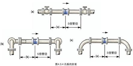
(1) When installing the orifice flowmeter, there should be a section of measuring pipe. At least keep the equal diameter straight pipe section of the first 10DN and the rear 5DN to improve the measurement accuracy.
(2) If you need to install valves before and after the orifice flowmeter, it is best to select the gate valve and fully open during operation. The regulating valve should be in the pipeline after 5DN downstream.
(3) The inner diameter of the impulse pressure pipeline is related to the length of the pipeline and the degree of contamination of the medium. Usually, a pipe with an inner diameter of 8-12mm is used within 45 meters.
(4) The horizontal section of the pressure pipe should be in the same horizontal plane when measuring the liquid flow. If the throttle is installed on the vertical pipeline, the short pipes should be separated by a certain distance (in the vertical direction). This has an effect on the zero point of the differential pressure transmitter and should be corrected by “zero point shift.
(5) The pressure piping should be supported by a firm support. The two pressure-taking pipelines should be as close as possible to each other and far away from the heat source or vibration source. When measuring the water vapor flow, they should be wrapped together with insulation materials. When necessary (for example, the temperature is below 0°C), a heat tracing tube should be added to prevent freezing. When measuring the dirt flow, an isolator or settler should be attached.
(6) The state of single-phase fluid must always be maintained in the impulse piping.
When the measured fluid is a gas, all the pressure in the impulse pipeline (including the pressure chamber of the differential pressure gauge) is in the gas phase.
When the measured fluid is a liquid, all the pressure pipes are in liquid phase, and there must be no bubbles.
For this reason, a drain valve should be installed at the lowest point of the impulse pressure pipeline or an exhaust valve should be installed at the highest point. Pay special attention to the new installation or maintenance of the differential pressure transmitter.
Orifice plate installation direction
The installation direction of the orifice flowmeter is not specified. But there is a rule that the flow direction of the medium cannot be reversed.
The orifice flowmeter can be installed according to the flow direction of the arrow of the flowmeter. that’s it.
In addition, the horizontal or vertical installation of the orifice flowmeter does not affect the measurement.
Orifice flow meter installation guidelines
(1) Before the instrument is installed, the process pipeline should be purged. Prevent the ferromagnetic substances remaining in the pipeline from adhering to the instrument, affecting the performance of the instrument, or even damaging the instrument. If it is unavoidable, a magnetic filter should be installed at the entrance of the meter. The instrument itself does not participate in the air sweep before production to avoid damage to the instrument.
(2) Before the instrument is installed in the process pipeline, it should be checked for damage.
(3) The installation form of the instrument is divided into vertical installation and horizontal installation. If it is installed vertically, ensure that the angle between the center vertical line and the vertical line of the instrument is less than 2°. If it is installed horizontally, ensure that the angle between the horizontal center line of the instrument and the horizontal line is less than 2°.
(4) The upstream and downstream pipelines of the instrument should have the same caliber of the instrument, and the connecting flange or thread should match the flange and thread of the instrument. The length of the upstream straight pipe section of the instrument should be at least 5 times the nominal diameter of the instrument, and the length of the downstream straight pipe section shall be greater than or equal to 250mm.
(5) Because the meter transmits signals through magnetic coupling. Therefore, in order to ensure the performance of the instrument, no ferromagnetic materials are allowed to exist at least 250px around the installation.
(6) The meter for measuring gas is calibrated under a specific pressure. If the gas is directly discharged to the atmosphere at the outlet of the meter, it will cause a pressure drop at the float and cause data distortion. If it is such a working condition, a valve should be installed at the outlet of the instrument.
(7). The instrument installed in the pipeline should not be subjected to stress. The entrance and exit of the meter should be supported by suitable pipes to keep the meter in a state of small stress.
(8) Be especially careful when installing PTFE (polytetrafluoroethylene) lined meters. Because PTFE will deform under pressure, do not overtighten flange nuts at will.
(9) For instruments with liquid crystal display, try to avoid direct sunlight to the display during installation to reduce the service life of the liquid crystal.
(10) Jacket type is required when measuring low temperature media.
Orifice plate installation in vertical line
Orifice flowmeters can be installed vertically. Points to note when installing vertically:
(1) When measuring liquid flow, the flow sensor can be installed vertically. The fluid is required to flow from bottom to top to ensure that the pipe is full.
If the flow can be guaranteed to fill the pipe, the flow sensor can also be installed on the pipe that flows from top to bottom. Since the positive and negative pressure ports are no longer in the same horizontal position, the differential pressure transmitter should be migrated.
(2) When measuring gas flow
When measuring dry gas flow, the flow meter has no strict requirements on the flow direction of the fluid in the pipeline.
When measuring wet gas, the gas is required to flow from top to bottom.
More Featured Throttle Device


Sino-Inst offers 12 orifice plate flow meter products. About 90% of these are flow meters.
A wide variety of orifice flow meter options are available to you, such as brass, carbon steel. You can also choose from free samples.
Sino-Inst is an orifice plate flow meter supplier. Orifice plate flow meter products are most popular in Domestic Market, Southeast Asia, and Mid East.
You can ensure product safety by selecting from certified suppliers, including 375 with ISO9001, ISO14001, and Other certification.

Zhang Wei, possesses 20 years of experience as an automation instrumentation engineer, specializing in the research, design, installation, commissioning, and maintenance of automation instruments.
Face to various instrument communication protocols (such as Modbus, Profibus, etc.), with solid hardware circuit design and software programming skills (proficient in C language and PLC programming). Has extensive project experience; projects he has led and participated in have all achieved outstanding results, improving product accuracy, reducing costs, and increasing production efficiency.
Possesses excellent communication and coordination skills and a strong team spirit, enabling him to quickly respond to customer needs and provide high-quality automation instrumentation solutions.