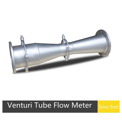
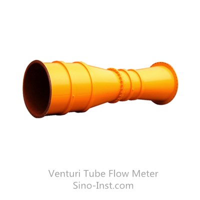
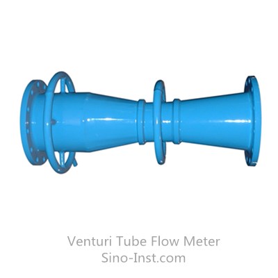
A Venturi tube is a throttling flow sensor developed based on the Venturi effect; it is a standard throttling device. Venturi tubes are classified into standard Venturi tubes and general-purpose Venturi tubes according to their structure.
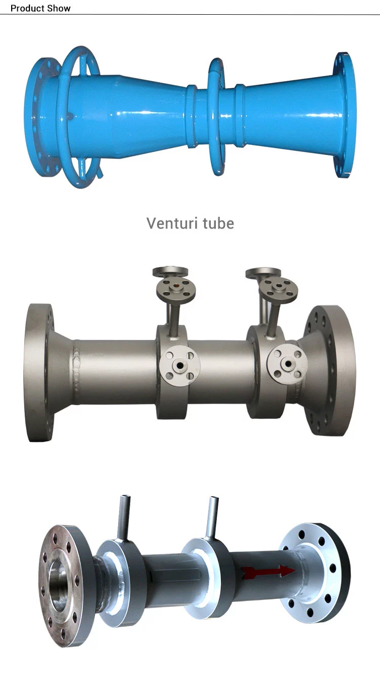
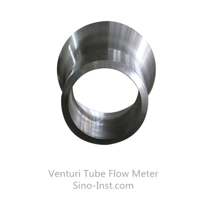
Standard (classic) Venturi tubes are further classified according to their manufacturing methods: standard Venturi tubes with a coarse-cast contraction section, standard Venturi tubes with a machined contraction section, and standard Venturi tubes with a coarse-welded iron plate contraction section. Standard Venturi tubes are designed and manufactured according to the national standard GB/T2624-2006 and calibrated according to the national standard JJG640-94.
General-purpose Venturi series flow sensors, in addition to inheriting the advantages of standard Venturi tubes such as high accuracy, good repeatability, low pressure loss, and short upstream straight pipe requirements, also possess the advantages of small size and anti-clogging. They can be used to measure complex flow problems such as bidirectional flow, multiphase flow, low flow velocity, large pipe diameter, and irregularly shaped pipes.
Diameter
DN8~DN3000
Accuracy
±0.5%-1.5%
Temp. range
-50℃~+600℃
Pressure
≤42MPa
Medium
Gas, water, Chemical, Crude, Slurry to even high temperature Steam
The standard (classic) Venturi tube is a standard throttling device designed and manufactured according to national standard GB/T2624 and verified according to national standard JJG640, requiring no calibration.
Among standard throttling devices, it requires the shortest upstream and downstream straight pipe sections and has the lowest permanent pressure loss.
It offers stable performance and high reliability.
It provides accurate calculations and low energy consumption.
It can be used for various dirty media, including liquids, gases, steam, and two-phase flows.
It has a simple structure, is easy to install, and is convenient to maintain.
The standard Venturi tube is approximately 2 to 5 times the pipe diameter.
Specifications
Parameter
Specification
Nominal Diameter
8 mm ≤ DN ≤ 3000 mm
— Rough cast convergent section
100 mm ≤ DN ≤ 1600 mm
— Machined convergent section
8 mm ≤ DN ≤ 250 mm
— Rough welded steel plate convergent section
100 mm ≤ DN ≤ 3000 mm
Throttle Diameter Ratio (β)
0.3 ≤ β ≤ 0.75
— Rough cast convergent section
0.3 ≤ β ≤ 0.75
— Machined convergent section
0.4 ≤ β ≤ 0.75
— Rough welded steel plate convergent section
0.4 ≤ β ≤ 0.7
Reynolds Number Range
2×10⁵ ≤ Re_D ≤ 2×10⁶
— Rough cast convergent section
2×10⁵ ≤ Re_D ≤ 2×10⁶
— Machined convergent section
2×10⁵ ≤ Re_D ≤ 10⁶
— Rough welded steel plate convergent section
2×10⁵ ≤ Re_D ≤ 2×10⁶
Accuracy Class
0.5, 1, 1.5, 2
Working Pressure
PN ≤ 42 MPa
Medium Temperature
-50 °C ≤ t ≤ 600 °C
Reference Standards
GB/T 2624-2006, JJG 640-94, ASME PTC 19.5-2004
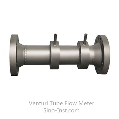
Connection Type
Flange, Welding, Threaded
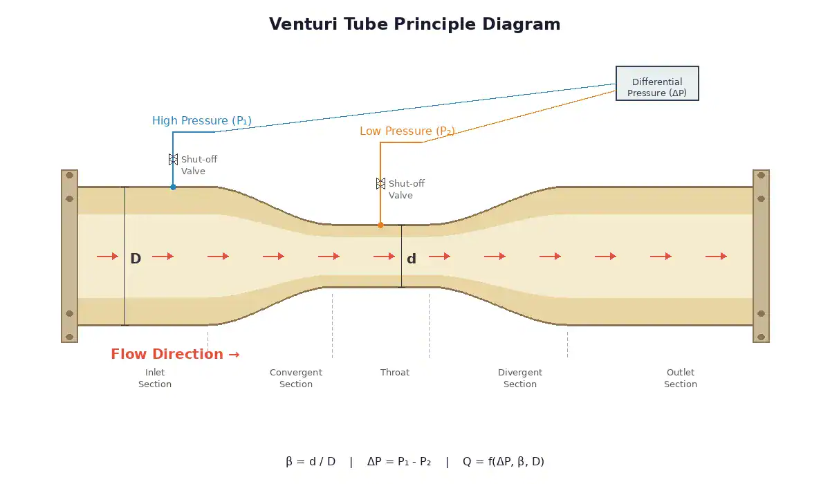
Venturi Flow Meter Working Principle
When fluid fills a pipe and flows through a throttling device, the flow velocity will locally contract at the venturi throat. This increases the velocity and decreases the static pressure, creating a pressure difference before and after the venturi throat.
The larger the fluid flow rate, the larger the pressure difference, allowing the flow rate to be measured. This measurement method is based on the flow continuity equation (law of conservation of mass) and Bernoulli’s equation (law of conservation of energy).
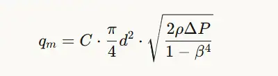
The Venturi flowmeter is based on Bernoulli’s equation and the Continuity equation.
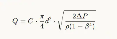
Core Formula:
Where:
Q — Volume flow rate (m³/s)
C — Discharge coefficient (typically 0.95–0.99)
d — Throat diameter (m)
D — Pipe diameter (m)
β = d/D — Diameter ratio
ΔP = P₁ – P₂ — Differential pressure between upstream and throat (Pa)
ρ — Fluid density (kg/m³)
Derivation Logic:
Continuity equation: A₁V₁ = A₂V₂ — as the cross-section narrows, velocity increases.
By measuring the pressure difference ΔP between the upstream section and the throat, the flow rate can be calculated.
Mass flow rate:
In practice, a gas expansion factor ε is introduced for compressible fluids (ε = 1 for liquids, ε < 1 for gases).
Venturi Flow Meter Installation Requirements
Before installation, verify that the flowmeter’s serial number, tag number, and specifications match the pipeline conditions and flow range.
For newly installed pipeline systems, flushing and scavenging are essential before installing the orifice plate to prevent blockage or damage from debris.
The center of the throttling device should be coaxial with the pipeline center, with a coaxiality error not exceeding ±[0.015*(1/β)-0.015]. Furthermore, the throttling end plane should be perpendicular to the pipeline, with an error not exceeding ±1°.
During flowmeter installation, the gasket should not protrude into the pipeline wall after clamping.
The flowmeter installation site must be airtight, with no leakage allowed. Pressure testing should be performed after installation.
The pressure-conducting pipe should be laid vertically or at an angle, with an inclination not less than 1:12. For fluids with higher viscosity, the inclination should be increased. When the differential pressure signal transmission distance exceeds 3 meters, the pressure-sensing pipe should be inclined in sections, and a gas collector and a settling device should be installed at each highest and lowest point.
If valves need to be installed before and after the flow meter, gate valves are preferred and should be fully open during operation; regulating valves should be installed in the pipeline 5DN downstream.
The pressure-sensing pipeline should be supported by a sturdy bracket. Two pressure-sensing pipelines should be as close as possible to each other and away from heat or vibration sources. When measuring water vapor flow, they should be wrapped together with insulation material. If necessary (e.g., below 0℃), a heat tracing pipe should be added to prevent freezing. When measuring dirty flow, an isolator or settling device should be installed.
When measuring liquid flow, the horizontal sections of the pressure-sensing pipe should be in the same horizontal plane. If a throttling device is installed on a vertical pipeline, the short pressure-sensing pipes should be spaced a certain distance apart (vertically). This will affect the zero point of the differential pressure transmitter and should be corrected using “zero point migration”.
The inner diameter of the pressure tapping line is related to the line length and the degree of contamination of the medium. Generally, a pipe with an inner diameter of 8-12 mm is used for lengths up to 45 meters.
The pressure tapping line must always maintain a single-phase fluid state. When the measured fluid is gas, the pressure tapping line (including the pressure chamber of the differential pressure gauge) must be entirely gaseous; when the measured fluid is liquid, the pressure tapping line must be entirely liquid. Absolutely no air bubbles are allowed. Therefore, a drain valve should be installed at the lowest point of the pressure tapping line, or an air vent valve at the highest point. Special attention should be paid to this when installing or repairing differential pressure transmitters.
Straight Pipe Requirements for Venturi Flow Meter Installation
Based on ISO 5167-4 (equivalent to GB/T 2624), the minimum straight pipe length requirements for classical Venturi tubes are as follows (expressed as multiples of pipe internal diameter D):
Downstream: ≥ 4 throat diameters (4d) — no special requirements.
Upstream Straight Length Requirements (Table 1, values in ×D):
β Ratio
Single 90° Bend
Two or More 90° Bends
Reducer (1.33D→D)
Expander (0.67D→D)
Reducer (3D→D)
Expander (0.75D→D)
Full Bore Ball/Gate Valve
A / B
A / B
A / B
A / B
A / B
A / B
A / B
0.30
8 / 3
8 / 3
4 / —
4 / —
2.5 / —
2.5 / —
2.5 / —
0.40
8 / 3
8 / 3
4 / —
4 / —
2.5 / —
2.5 / —
2.5 / —
0.50
9 / 3
10 / 3
4 / —
5 / 4
5.5 / 2.5
2.5 / —
3.5 / 2.5
0.60
10 / 3
10 / 3
4 / —
6 / 4
8.5 / 2.5
3.5 / 2.5
4.5 / 2.5
0.70
14 / 3
18 / 3
4 / —
7 / 5
10.5 / 2.5
5.5 / 3.5
5.5 / 3.5
0.75
16 / 8
22 / 8
4 / —
7 / 6
11.5 / 3.5
6.5 / 4.5
5.5 / 3.5
Notes:
Column A: Zero additional uncertainty values
Column B: 0.5% additional uncertainty values
“—”: Column A already represents the minimum; no data available for shorter lengths
Temperature pockets or wells installed upstream shall not exceed 0.13D in diameter and shall be located at least 4D upstream of the upstream tapping plane Idsolutions-acp
Bend radius of curvature shall be ≥ pipe diameter
Key takeaway: Venturi tubes require significantly shorter upstream straight lengths than orifice plates, because the convergent section itself helps condition the flow profile. Higher β ratios require longer straight lengths.
In addition to regular products, we support customization
Sanitary flow meters are flow measurement instruments specifically designed for industries with high hygiene requirements, such as food and pharmaceuticals. They feature excellent cleanability and resistance to contamination. Sino-Inst supplies a range of sanitary flow meters, including electromagnetic, Coriolis, turbine,…
Accurate measurement of flare gas flow presents a significant challenge in industrial process control. This is primarily due to the extreme variability of flare gas flow rates, the unpredictability of gas composition, and harsh operating environments. Thermal mass flow meters…
Positive displacement flow meters(PD Meter) are versatile and cost-effective. They can be used to measure clean, corrosive fluids and gases. When you need a high-precision flow meter at a reasonable price, a positive displacement flow meter is often the best…
Why Natural Gas Flow Measurement is Pivotal? Natural gas is a vital energy source, providing electricity to industries, homes, and businesses worldwide. High-precision natural gas flow measurement is essential for ensuring fair trade, accurate trade measurement, and safe and efficient…
Heating oil flow meters are devices that measure the flow rate of heating oil through a pipeline. Ensuring accurate monitoring and control of fuel consumption. They are essential in various industries. Including manufacturing, energy, and transportation, where heating oil is…
Measuring the flow of media at extreme temperatures in industrial processes has always been a challenging task, whether it’s high-temperature gas, high-temperature liquid, or extremely low-temperature liquid. Conventional flow meters may experience reduced accuracy or even damage when exposed to…
Gas flow measurement is an essential technology in many industrial processes. For example, in the production of chemical products, accurate measurement of the flow of gases such as oxygen and nitrogen can ensure that the reactants are added to the…
The Venturi differential pressure flow meter, paired with the Sino-Inst high static pressure intelligent differential pressure sensor, features wide applicability, high reliability, low pressure loss, simple structure, convenient maintenance, and stable performance. It is widely used in the flow measurement of various gases, liquids, and steam in petroleum, chemical, metallurgical, power, heating, and water supply industries, and can also be used for flow measurement of various dirty media.
As a manufacturer of Venturi flow meters, Sino-Inst supports customized parameters, including pressure, material, and temperature. Please feel free to contact us.
Zhang Wei, possesses 20 years of experience as an automation instrumentation engineer, specializing in the research, design, installation, commissioning, and maintenance of automation instruments.
Face to various instrument communication protocols (such as Modbus, Profibus, etc.), with solid hardware circuit design and software programming skills (proficient in C language and PLC programming). Has extensive project experience; projects he has led and participated in have all achieved outstanding results, improving product accuracy, reducing costs, and increasing production efficiency.
Possesses excellent communication and coordination skills and a strong team spirit, enabling him to quickly respond to customer needs and provide high-quality automation instrumentation solutions.