


Coriolis effect refers to a phenomenon in which an object moving in a rotating coordinate system is deflected. When this effect occurs, the acceleration relative to the body will be perpendicular to the relative velocity currently carried. Thus, the Coriolis effect will be stronger or weaker depending on the speed at which the object is moving.
The Coriolis effect is an effect caused by the Coriolis force, which is a deflection component of the centrifugal force generated by the rotation of the earth. It deflects the fluid in the northern hemisphere to the right and the fluid in the southern hemisphere to the left. This phenomenon was first discovered by Coriolis (G.C.de Coriolis 1835), so it is called the Coriolis effect or Coriolis acceleration.
Its magnitude is proportional to the sine of the latitude angle, decreasing from the equator to the poles. The Coriolis effect has a great influence on the atmospheric and ocean circulation. Under its influence, a huge clockwise ocean circulation is formed in the northern hemisphere. In the southern hemisphere, a counterclockwise ocean circulation is formed.
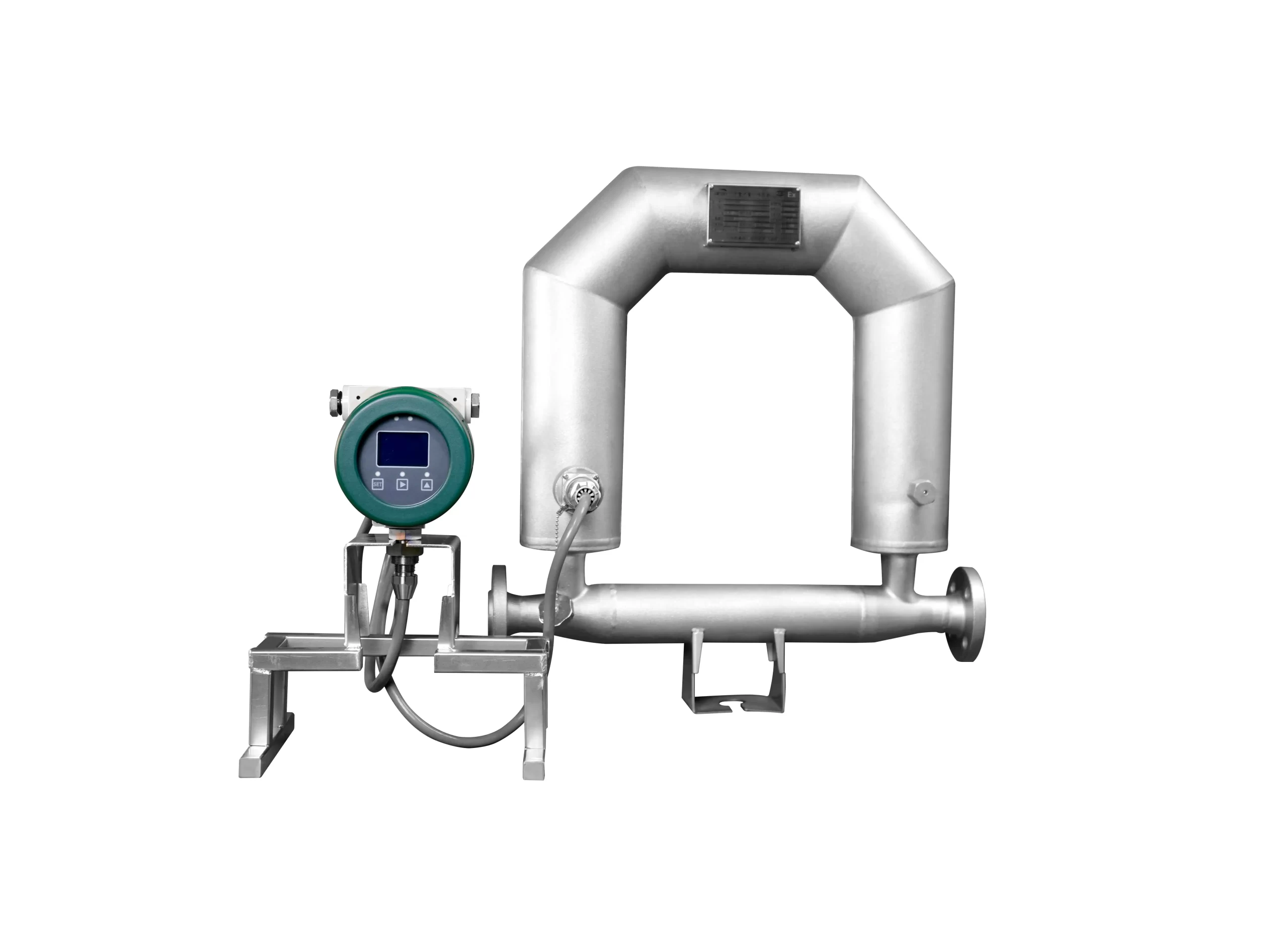
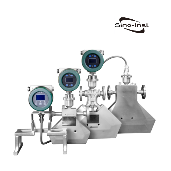
The mass flow sensor consists of a measuring tube, a measuring tube drive device, a position detector, a supporting structure, a temperature sensor, a housing, and other parts.
When a particle in a tube that rotates around a fixed point P (rotation center) moves toward or away from the rotation center, an inertial force will be generated. The principle is shown in the figure:
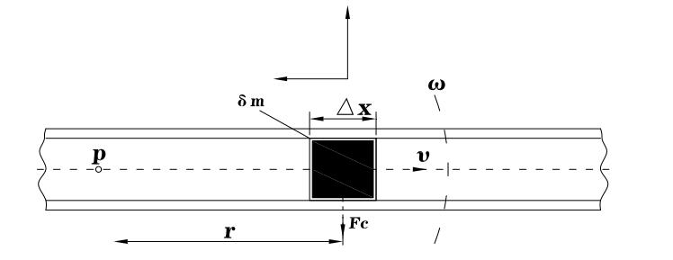
In the figure, a particle with a mass of δm moves to the right in the pipe at a uniform speed υ. The pipe rotates around a fixed point P at an angular velocity ω.
At this time, the particle will obtain two acceleration components:
- Normal acceleration αr (centripetal acceleration), whose magnitude is equal to ω2r and its direction is toward point P.
- Tangential acceleration αt (Coriolis acceleration), whose magnitude is equal to 2ωυ and its direction is perpendicular to αr.
The force generated by the tangential acceleration is called the Coriolis force. Its magnitude is equal to Fc=2ωυδm. In the figure, the fluid δm=ρA×ΔX. Therefore, the Coriolis force can be expressed as:
ΔFc=2ωυ×δm=2ω×υ×ρ×A×ΔX=2ω×δqm×ΔX
Where A is the cross-sectional area of the pipe.
δqm=δdm/dt=υρA
For a specific rotating pipe, its frequency characteristics are certain, and ΔFc depends only on δqm. Therefore, the mass flow rate can be measured by directly or indirectly measuring the Coriolis force. The Coriolis principle mass flowmeter works according to the above principle.
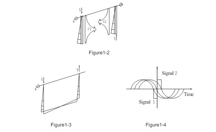
The actual flow sensor does not realize rotational motion, but instead uses pipe vibration. The principle diagram is shown in Figure .
The two ends of a curved pipe are fixed. A vibration force (according to the resonant frequency of the pipe) is applied to the pipe at the middle position of the two fixed points. It is made to vibrate with its natural frequency ω around the fixed point as the axis.
When there is no fluid flowing in the pipe, the pipe is only affected by the external vibration force. The two halves of the pipe vibrate in the same direction and there is no phase difference.
When there is fluid flowing, it is affected by the Coriolis force Fc of the medium particles flowing in the pipe (the Coriolis forces F1 and F2 in the two halves of the pipe are equal in magnitude and opposite in direction (Figure 1.2). The two halves of the pipe twist in opposite directions, resulting in a phase difference (Figure 1.3, Figure 1.4). This phase difference is proportional to the mass flow rate.
The design of the sensor is to convert the measurement of the Coriolis force into the measurement of the phase time difference on both sides of the vibrating tube. This is the working principle of the Coriolis mass flowmeter.
Mass flowmeter is an instrument used to accurately measure the mass flow rate of fluid (liquid or gas). With the development of technology, many types of mass flowmeters have appeared on the market. Thermal mass flowmeter and Coriolis mass flowmeter are two types with relatively high accuracy and are more commonly used. So what is the difference between them?
- Different measurement principles
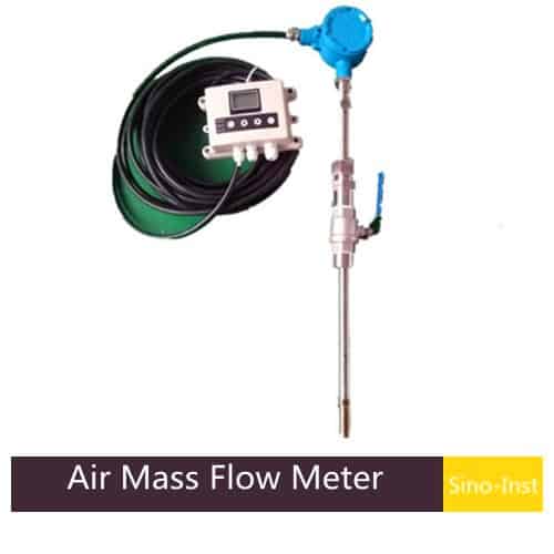
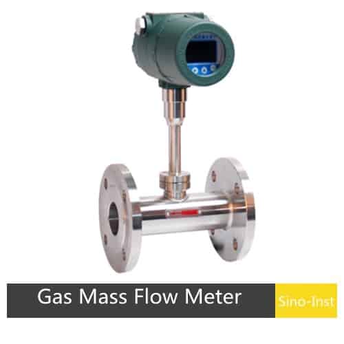
Thermal mass flowmeter uses the heat capacity of the fluid to measure the mass flow rate. The core of the device is a heater and one or two temperature sensors. The power applied by heating (using one sensor) or the temperature difference between the two sensors is proportional to the mass flow rate of the fluid. Thermal mass flowmeter is mainly used for gas.
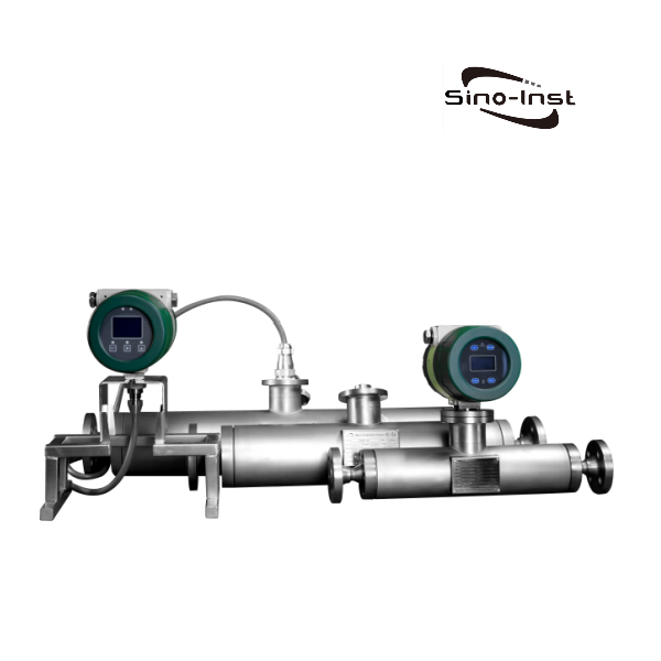
Coriolis mass flowmeter uses the Coriolis effect to directly measure the mass flow rate of the fluid.
- Different measurement accuracy
The measurement accuracy of Coriolis mass flowmeter is very high, which can reach 0.1% or higher. The accuracy of thermal mass flowmeter is usually ±1.5%.
- Different applicable fluids
Thermal mass flowmeter is suitable for gas. But it cannot measure liquids.
Coriolis mass flowmeter is suitable for complex fluids such as high viscosity, high viscosity and mud solution. It can also be used to measure gas.
- Different environmental conditions
Although both flowmeters can work in high temperature and high pressure environments, the Coriolis mass flowmeter is not sensitive to changes in environmental conditions and fluid properties. The stability and reliability of the thermal mass flowmeter may be affected under high temperature and high pressure conditions.