
Differential pressure flow measurement represents a foundational and widely applied methodology in industrial process control. This technology operates on the principle, articulated by Bernoulli’s equation, that a fluid’s velocity is inversely related to its pressure. By introducing a precisely engineered constriction, known as a primary flow element, into a pipe, a localized pressure drop is created. This differential pressure is then measured by a secondary instrument, a differential pressure flow sensor, and correlated to the volumetric flow rate.
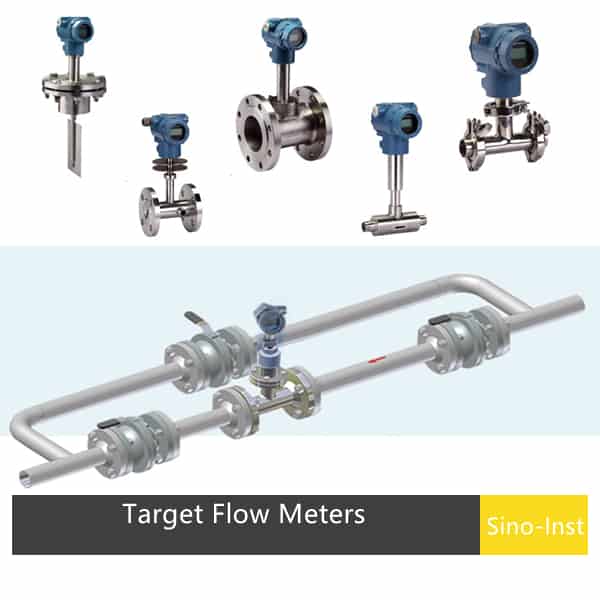
We will analyze some of the most common flow elements, including orifice plates, venturi tubes, flow nozzles, Pitot tubes, and average Pitot tubes (Annubar). We will delve into the trade-offs for each primary flow element in terms of accuracy, permanent pressure drop, initial cost, installation complexity, and long-term operating costs, helping you make informed choices based on your specific process conditions.
The Foundational Principle: Bernoulli’s Equation and Flow Measurement
Before we can begin to evaluate the specific hardware used to measure fluid flow, we must first grapple with the physical law that makes such measurement possible. Imagine a river. Where the river is wide and deep, the water moves slowly, almost lazily. Where it narrows into a gorge, the same volume of water must pass through a smaller space, and so its speed increases dramatically. This intuitive observation is a reflection of a fundamental concept in fluid dynamics: the principle of conservation of mass. What is perhaps less intuitive is what happens to the water’s internal pressure during this change.
This is where the work of the 18th-century Swiss mathematician Daniel Bernoulli becomes our guide. Bernoulli’s principle, in its simplified form, posits an inverse relationship between the velocity of a fluid and its static pressure. As the fluid speeds up through the narrow gorge, its internal pressure decreases. When it emerges into a wider channel and slows down, its pressure increases again. It is this predictable change in pressure, induced by a change in geometry, that lies at the heart of differential pressure flow measurement.
Understanding Pressure and Velocity
To properly understand this, we must distinguish between two types of pressure. Static pressure is the pressure you would feel if you were moving along with the fluid, the pressure exerted by the fluid in all directions at rest. Dynamic pressure is the pressure associated with the fluid’s motion or kinetic energy. Bernoulli’s equation tells us that for a fluid flowing horizontally, the sum of its static pressure and dynamic pressure remains constant.
Therefore, if we force a fluid to accelerate by passing it through a constriction, its kinetic energy, and thus its dynamic pressure, must increase. To keep the total energy constant, its potential energy, in the form of static pressure, must decrease. This creates a difference in static pressure between the unrestricted upstream section of the pipe and the constricted section.
How a Restriction Creates a Measurable Difference
All of the primary devices we will discuss—the orifice, the venturi, the nozzle—are essentially carefully designed restrictions placed within a pipe. They are the engineered equivalent of the river’s narrow gorge. Their purpose is singular: to create a known, predictable, and measurable drop in pressure.
The magnitude of this pressure drop is directly related to the square of the fluid’s velocity. This means that if the flow rate doubles, the differential pressure quadruples. This non-linear relationship is a defining characteristic of this measurement technique. By measuring the difference in static pressure just before the restriction (P1) and at the point of maximum constriction (P2), we obtain the differential pressure (ΔP = P1 – P2). Armed with this value, and knowing the precise geometry of the pipe and the restriction, we can calculate the flow rate.
The Role of the Differential Pressure Flow Sensor
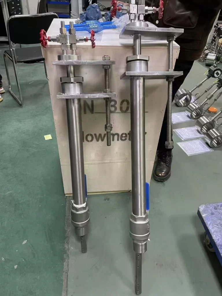
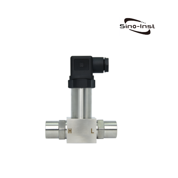
The primary element—the orifice plate or Venturi tube—does not measure flow by itself. It is a passive, mechanical component that merely conditions the fluid to produce a pressure difference. The actual measurement is performed by a secondary device: a differential pressure (DP) transmitter or sensor.
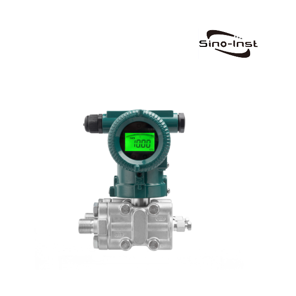
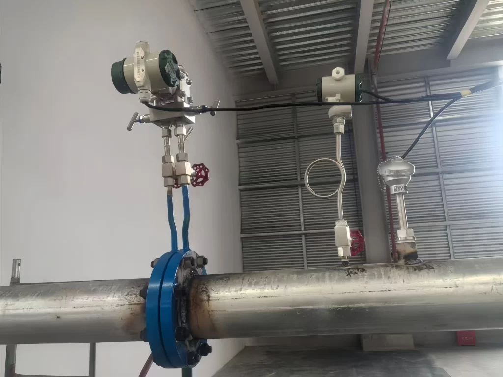
This instrument has two ports. One is connected to a pressure tap upstream of the primary element, and the other is connected to a tap at the constriction. Inside the transmitter, a sensitive diaphragm or sensor detects the minute difference in pressure between the two ports. This physical pressure is then converted into a standardized electrical signal, typically a 4-20 mA analog signal or a digital signal via protocols like HART or Foundation Fieldbus.
This signal is then sent to a control system, recorder, or display, where it is converted into a flow rate reading (e.g., gallons per minute or cubic meters per hour) using the appropriate mathematical formula for the specific primary element. The reliability of the entire system depends just as much on the accuracy and stability of these differential pressure flow sensors as it does on the primary element itself.

A Comparative Overview of Primary Flow Elements
Choosing among the different types of flow elements requires a careful consideration of trade-offs. No single device is superior in all circumstances. The selection process is a nuanced exercise in balancing performance requirements against economic realities. The following table provides a high-level comparison of the most common primary elements.
| Feature | Orifice Plate | Venturi Tube | Flow Nozzle | Pitot Tube | Annubar Element |
| Initial Cost | Very Low | Very High | High | Low | Medium |
| Permanent Pressure Loss | High | Very Low | Medium | Very Low | Very Low |
| Typical Accuracy | ±1.0% to ±2.0% | ±0.5% to ±1.0% | ±0.75% to ±1.5% | ±3.0% to ±5.0% | ±1.0% to ±2.0% |
| Suitability for Slurries | Poor | Good | Fair | Poor | Poor |
| Required Straight Pipe Run | Long | Short | Medium | Medium | Medium |
| Wear Resistance | Poor | Excellent | Good | Fair | Good |
| Primary Use Case | General purpose, cost-sensitive | High accuracy, energy-critical | High velocity, steam/gas | Spot checks, large ducts | Gas/clean liquid, low pressure loss |
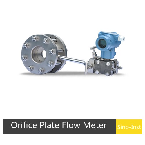
The Orifice Plate: A Study in Simplicity and Compromise
The orifice plate is, by a significant margin, the most common primary flow element in use today. Its ubiquity is not due to superior performance, but to its profound simplicity and low cost. At its core, an orifice plate is little more than a thin piece of metal with a precisely machined hole in the center, clamped between two pipe flanges. It is the brute-force method of creating a pressure differential.
Imagine the fluid flow as organized traffic on a multi-lane highway. The orifice plate is like suddenly closing all but one lane without any warning. The result is a chaotic traffic jam just before the restriction, followed by a rush of vehicles accelerating through the single open lane. This abrupt constriction forces a significant increase in fluid velocity and a corresponding sharp drop in pressure.
Design and Construction of an Orifice Plate
The standard orifice plate is a concentric design, meaning the bore is centered in the plate. The upstream edge of the bore is critical; it must be sharp and square to ensure a predictable flow contraction. Any rounding or nicking of this edge will alter the discharge coefficient—a dimensionless number that corrects the theoretical flow equation for real-world effects—and introduce measurement errors (Morrow, 2018).
For applications involving solids or entrained gases, other designs exist. An eccentric orifice plate has the bore located at the bottom of the pipe to allow solids to pass through, while a segmental orifice has a D-shaped opening at the top or bottom to allow gases or solids to pass, respectively.
Pressure taps, the small holes through which the pressure is sensed, can be located in several positions. Flange taps are the most common, drilled directly into the flanges holding the plate. Vena contracta taps are positioned to measure the pressure at the point of narrowest fluid stream, which occurs slightly downstream of the plate, yielding the maximum differential pressure.
Installation and Best Practices
The apparent simplicity of the orifice plate is deceptive. Its accuracy is highly sensitive to the condition of the flow approaching it. The “traffic” must be smooth and orderly. Any turbulence, swirl, or asymmetry in the flow profile caused by upstream elbows, valves, or other fittings will severely degrade measurement accuracy.
To counteract this, industry standards, such as those from the American Gas Association (AGA) and the International Organization for Standardization (ISO), mandate long runs of straight, unobstructed pipe both upstream and downstream of the orifice plate. The required length can be substantial—often 20 to 50 pipe diameters upstream and 5 to 10 diameters downstream. In large pipes, this requirement can translate to a very long, expensive, and space-consuming installation. Flow conditioners, which are bundles of tubes or vanes installed upstream, can help to smooth the flow profile and reduce the required straight-pipe run, but they add cost and complexity.
Advantages: Cost-Effectiveness and Versatility
The primary appeal of the orifice is economic. The plate itself is inexpensive to manufacture, and the use of standard pipe flanges for installation keeps costs down. This makes it an attractive choice for general-purpose monitoring where pinpoint accuracy is not the paramount concern. It is well-understood, with decades of empirical data supporting its use across a vast range of fluids, pipe sizes, and process conditions.
Disadvantages: High Pressure Loss and Wear
The economy of the orifice plate comes at a significant operational price: high permanent pressure loss. After the fluid accelerates through the bore, it does not fully recover its original pressure. The abrupt expansion on the downstream side creates significant turbulence and eddies, dissipating energy as heat. This unrecovered pressure, known as permanent pressure loss, can be as high as 50% to 80% of the differential pressure created.
Think of it as a tax on your process. This lost pressure must be restored by a pump or compressor, which consumes energy. Over the lifetime of a facility, the cumulative energy cost to overcome the pressure loss from an orifice plate can far exceed its low initial purchase price. This is a critical consideration in any economic analysis. Furthermore, the sharp edge of the orifice is susceptible to erosion from abrasive fluids and corrosion, which alters the bore diameter and degrades accuracy over time, necessitating periodic inspection and replacement.
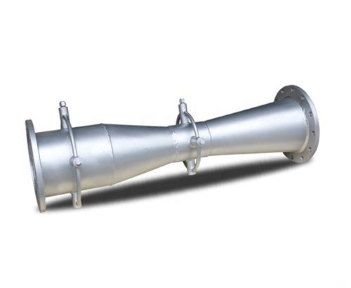
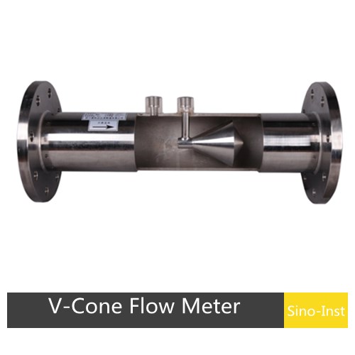
The Venturi Tube: The Epitome of Hydraulic Efficiency
If the orifice plate is a sudden roadblock, the Venturi tube is a masterfully designed system of highway ramps. It is an instrument born from a deep appreciation for the physics of fluid motion. Developed by Clemens Herschel in the 19th century and named in honor of the Italian physicist Giovanni Battista Venturi, this device is engineered for maximum efficiency.
A classic Venturi tube consists of three sections: a cylindrical inlet that matches the pipe diameter, a converging conical section that smoothly accelerates the fluid, and a long, gently diverging conical section (the diffuser) that decelerates the fluid and recovers its pressure. The pressure taps are located in the upstream cylindrical section and at the “throat,” the point of minimum diameter and maximum velocity.
The Anatomy of a Venturi Tube: A Study in Fluid Dynamics
The genius of the Venturi lies in its gradual, streamlined geometry. The converging inlet guides the fluid into the throat with minimal turbulence. This smooth acceleration process is highly efficient, converting static pressure into dynamic pressure predictably.
The most important part, however, is the long recovery cone. This section acts in reverse, carefully managing the fluid’s expansion. By decelerating the flow gradually, it prevents the formation of the large-scale turbulence and energy-wasting eddies that plague the downstream side of an orifice plate. This allows the fluid to regain a very high percentage of its original static pressure. The permanent pressure loss of a well-designed Venturi tube is remarkably low, typically only 10% to 20% of the differential pressure it generates.
Why the Venturi Tube Minimizes Pressure Loss
Let us return to our traffic analogy. The Venturi’s converging section is like a long on-ramp that smoothly merges multiple lanes of traffic into one, allowing cars to accelerate without chaos. The throat is the single high-speed lane. The diffuser cone is the crucial off-ramp, which is equally long and gradual, allowing the fast-moving traffic to spread out and slow down in an orderly fashion, rejoining the main highway flow with minimal disruption.
This careful management of the fluid’s energy is what distinguishes the Venturi. The energy that is wasted as turbulence and heat in an orifice installation is conserved in a Venturi. This directly translates into lower pumping and compression costs over the life of the instrument. For large-scale applications, such as municipal water systems or natural gas pipelines, these energy savings can be enormous, easily justifying the Venturi’s higher initial cost.
Application Spotlight: Where High Efficiency Matters
The Venturi tube is the preferred choice in applications where pressure loss is a major concern. This includes lines with low available pressure, systems where pump capacity is limited, or any process where energy efficiency is a primary driver.
Its streamlined, obstruction-less design also makes it highly suitable for measuring fluids containing suspended solids, or slurries. Unlike an orifice plate, which can be damaged by abrasive particles and where solids can build up against the upstream face, the Venturi’s smooth profile allows solids to pass through without causing significant wear or accumulation. This makes it a durable and reliable choice for challenging applications like wastewater treatment, mining, and chemical processing.
Balancing Cost Against Long-Term Performance
The main barrier to the widespread adoption of the Venturi tube is its cost and size. It is a much larger, heavier, and more complex device to manufacture than a simple orifice plate, leading to a significantly higher purchase price. Its length also means it requires more space for installation.
However, a proper engineering decision must be based on a total lifecycle cost analysis. One must ask: what is the total cost of owning this instrument over 10 or 20 years? When the continuous energy savings from its low pressure loss are factored in, the Venturi often emerges as the more economical choice in the long run, particularly in continuous, high-flow-rate applications (Bennett, 2023). It represents a long-term investment in process efficiency and measurement stability.
The Flow Nozzle: A Robust Hybrid for Demanding Conditions
The flow nozzle can be understood as a compromise, a hybrid design that attempts to capture some of the best attributes of both the orifice plate and the Venturi tube. It offers better pressure recovery than an orifice but is more compact and less expensive than a full Venturi.
Structurally, a flow nozzle consists of a rounded, elliptical inlet that smoothly contracts the flow, followed by a short cylindrical throat. It has no recovery cone or diffuser section. The fluid discharges from the throat directly into the downstream pipe, much like an orifice plate. This abrupt expansion means that the pressure recovery is not as good as a Venturi’s, but the smooth, guided contraction on the inlet side makes it far more efficient than an orifice plate. Its permanent pressure loss typically falls between that of an orifice and a Venturi, in the range of 30% to 60% of the differential pressure.
Combining Features of the Orifice and Venturi
Think of the flow nozzle as having the well-designed on-ramp of the Venturi but the sudden end of the orifice. The contoured inlet guides the fluid into the throat with minimal turbulence, resulting in a stable and predictable discharge coefficient. This makes it more accurate and repeatable than an orifice, especially at higher flow rates.
However, the lack of a diffuser means that the energy recovery is incomplete. The high-velocity jet exiting the throat expands into the larger pipe diameter, creating significant turbulence and dissipating energy. While less wasteful than an orifice, it cannot match the exceptional efficiency of the Venturi.
Performance with High-Velocity and Erosive Fluids
The primary advantage and most common application of the flow nozzle is in the measurement of high-velocity, non-viscous, erosive fluids. This includes fluids like high-pressure steam, gases, and clean liquids where flow velocities are too high for an orifice plate.
The hardened, contoured surface of the nozzle is far more resistant to the erosive effects of high-velocity flow than the sharp edge of an orifice. While an orifice edge can quickly become rounded, changing its measurement properties, the nozzle’s profile maintains its integrity for much longer. This makes it the standard choice for measuring steam flow in power plants and other industrial boiler applications, where both high velocity and erosive potential are present. Its capacity to handle higher flow rates than an orifice of the same bore size also allows for the use of smaller, less expensive pipe sizes in some designs.
Installation Nuances Compared to Other Elements
The installation of a flow nozzle can be more complex than that of an orifice plate. It is often welded directly into the pipe, though flanged models are also available. This can make inspection or replacement more difficult. Like the orifice, it is sensitive to upstream flow disturbances and requires significant straight pipe runs to achieve its specified accuracy. The table below outlines typical application suitability.
| Application Condition | Orifice Plate | Venturi Tube | Flow Nozzle |
| Clean Liquids (Low Velocity) | Excellent | Good | Good |
| Clean Gases (Low Velocity) | Excellent | Good | Good |
| High-Velocity Steam/Gas | Poor | Good | Excellent |
| Slurries / Dirty Fluids | Poor | Excellent | Fair |
| Low-Pressure Lines | Poor | Excellent | Fair |
| Cost-Sensitive (Initial) | Excellent | Poor | Fair |
| Energy-Sensitive (Lifetime) | Poor | Excellent | Good |
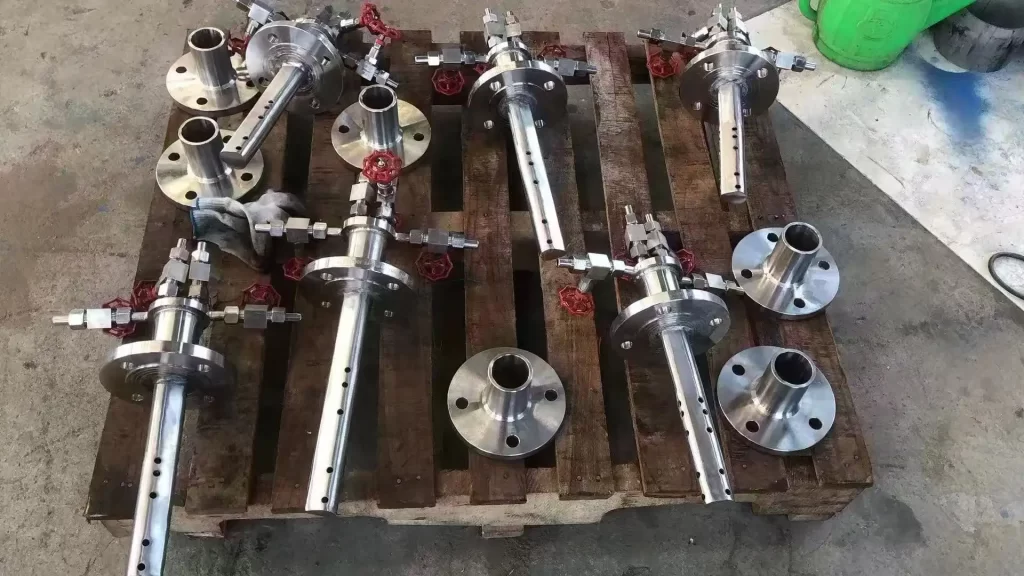
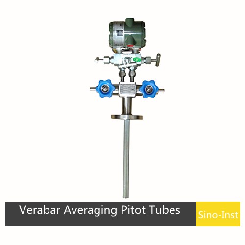
The Pitot Tube: Capturing Velocity at a Single Point
The Pitot tube is fundamentally different from the devices we have discussed thus far. While orifice plates, Venturi tubes, and flow nozzles are “full-bore” meters that constrict the entire flow, the Pitot tube is an “insertion” device. It measures velocity at a single point within the flow stream. Its operation is a direct and elegant application of Bernoulli’s principle.
A simple L-shaped Pitot tube has an opening facing directly into the flow. The fluid that enters this opening is brought to a complete stop, a condition known as stagnation. At this stagnation point, all the fluid’s kinetic energy (dynamic pressure) is converted into potential energy (pressure). The pressure inside the Pitot tube is therefore the total or stagnation pressure (Ptotal = Pstatic + P_dynamic).
The instrument also includes a second set of holes on the side of the tube, parallel to the flow direction. These holes are unaffected by the fluid’s motion and measure only the static pressure (Pstatic) of the surrounding fluid stream. A differential pressure sensor connected to these two sets of ports measures the difference between them, which is the dynamic pressure (ΔP = Ptotal – Pstatic = Pdynamic). From this dynamic pressure, the velocity at that specific point can be calculated.
The Classic Pitot Tube: Stagnation vs. Static Pressure
Imagine holding your hand out of the window of a moving car. The pressure you feel on your palm as it faces forward is the stagnation pressure. The pressure you would feel on the top or bottom of your hand, parallel to the airflow, is the static pressure. A Pitot tube is simply a more precise way of measuring both of these pressures simultaneously to find the difference.
This principle makes the Pitot tube a simple, robust, and inexpensive tool for measuring fluid velocity. It was originally invented by French engineer Henri Pitot in the early 18th century to measure the flow of the river Seine and remains a primary instrument for measuring airspeed on aircraft.
Limitations: From Point Measurement to Flow Profile
You might be asking a very perceptive question: if a Pitot tube only measures velocity at one point, how can it determine the total flow rate in a pipe? This question highlights the central limitation of the device. The velocity of a fluid in a pipe is not uniform. It is fastest at the center and slowest near the pipe walls due to friction. This distribution of velocities is called the flow profile.
To calculate the total volumetric flow rate, one must know the average velocity across the entire pipe cross-section. Using a single-point measurement from a Pitot tube to infer this average velocity assumes a well-developed and predictable flow profile. In many real-world industrial situations, with disturbances from valves and elbows, this is not a safe assumption. A measurement taken at the center of the pipe will overestimate the average velocity, while a measurement taken near the wall will underestimate it. This is why a simple Pitot tube is generally considered a low-accuracy device for volumetric flow measurement, often used for indicative readings or system diagnostics rather than for precise process control or custody transfer.
When to Use a Simple Pitot Tube
Despite this limitation, the simple Pitot tube has its place. Its major advantages are its extremely low permanent pressure loss—it presents a negligible obstruction to the flow—and its ease of installation. It can be installed in very large pipes or ducts where a full-bore meter like a Venturi would be prohibitively large and expensive. It can also be installed through a small connection on an existing pipe without requiring a full system shutdown, a process known as “hot tapping.”
Consequently, it is often used for troubleshooting, conducting system surveys in large air ducts (like in HVAC systems), or for applications where a rough estimate of flow is sufficient.
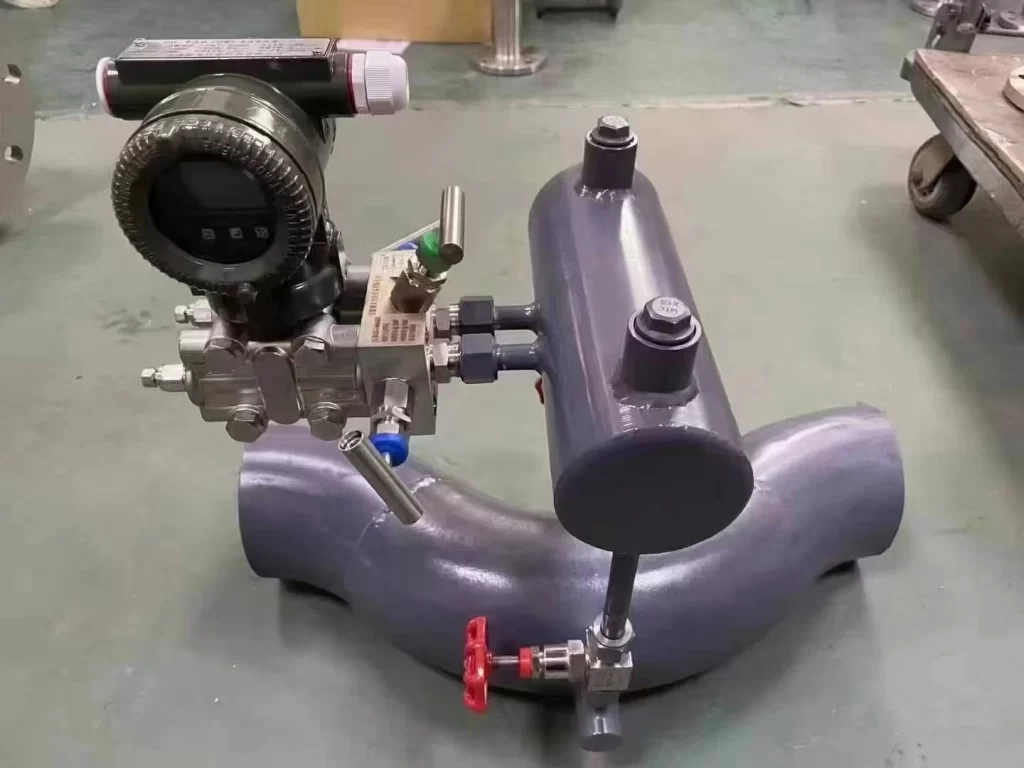
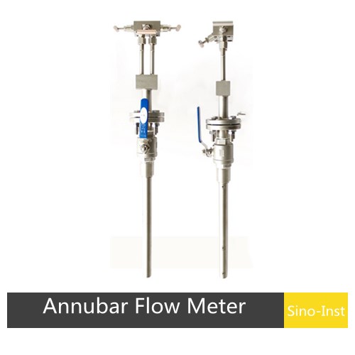
The Annubar Flow Element: An Advancement in Averaging Measurement
The Annubar flow element, a proprietary name from Emerson that is now often used generically, represents a significant evolution of the simple Pitot tube. It is an engineered solution designed specifically to overcome the single-point measurement limitation. It is a type of averaging Pitot tube.
An Annubar consists of a probe that spans the entire diameter of the pipe. Like a simple Pitot tube, it has an upstream-facing port to measure the total pressure. However, instead of a single port, it has a series of strategically located ports along its length. These ports are positioned according to a geometric averaging formula. The pressures from these individual ports are combined inside the probe, which produces a single, averaged total pressure signal. The probe also has a large port on its downstream side that measures a low-pressure reference, which is an amplified version of the static pressure.
From Single-Point to Multi-Point Averaging
By sampling the velocity at multiple points across the flow profile—near the walls, in the middle, and at intermediate points—the Annubar flow element mechanically calculates an average velocity that is much more representative of the true flow profile than a single-point measurement. This is analogous to conducting a survey. Asking one person their opinion gives you a single data point, which may or may not be representative of the whole group. Asking a carefully selected sample of people across different demographics gives you a much more accurate picture of the group’s overall opinion. The Annubar does the same for fluid velocity.
This multi-point averaging makes the Annubar flow element significantly more accurate and repeatable than a simple Pitot tube, bringing its performance into a range comparable with orifice plates, but with much lower pressure loss.
How the Annubar Flow Element Improves Accuracy
The design of the Annubar also incorporates features to enhance the signal. The unique shape of the probe is often designed to amplify the differential pressure signal. The downstream port measures a low pressure created in the wake of the probe, which is lower than the true static pressure. This results in a larger, more stable differential pressure signal (P1 – P2) than would be generated by a classic Pitot tube under the same flow conditions. A stronger signal is easier for the DP transmitter to measure accurately, especially at low flow rates.
Advantages: Low Permanent Pressure Loss and Easy Installation
Like the simple Pitot tube, the Annubar flow element offers the key advantages of very low permanent pressure loss and ease of installation. Since it is an insertion device with a small cross-sectional area, it creates very little blockage, resulting in negligible energy loss. This makes it an excellent choice for energy-conscious applications and for retrofitting into existing systems. It can be installed via hot-tapping, which is a major benefit for processes that cannot be easily shut down.
These features make the Annubar a popular and cost-effective choice for measuring the flow of clean liquids and gases, particularly in large pipes where devices like a Venturi or orifice would be impractical. It offers a compelling balance of reasonable accuracy, low energy consumption, and installation flexibility.
Considerations and Potential Drawbacks
The primary limitation of an Annubar flow element is that it is not suitable for dirty or fouling fluids. The small pressure-sensing ports can become clogged by particulates or scaling, leading to measurement failure. The probe itself can also be subject to flow-induced vibrations in high-velocity applications, which may require additional support. It remains sensitive to severe flow profile distortions, though less so than a single-point Pitot tube.
Selecting the Right Flow Element for Your Application
The choice among the different types of flow elements is not a matter of finding the “best” one, but of finding the right one for a specific set of circumstances. The decision rests on a careful evaluation of three pillars: the properties of the fluid, the conditions of the process, and the economic factors at play. A misapplication can lead to inaccurate measurements, high operating costs, or premature failure. Anyone navigating these choices may benefit from consulting comprehensive guides on differential pressure flow measurement solutions to make an informed decision.
Fluid Properties: Gas, Liquid, Steam, and Slurries
The nature of the fluid itself is the first consideration.
- Clean Liquids and Gases: All the discussed devices can handle clean fluids. The choice then depends more on pressure loss and cost considerations.
- Steam: The high velocity and erosive nature of steam often favor the robust design of a flow nozzle. An Annubar can also be used if the steam is clean.
- Slurries and Particulate-Laden Fluids: The smooth, obstruction-less bore of a Venturi tube makes it the superior choice for fluids that contain suspended solids. An orifice plate will erode quickly and can cause solids to accumulate, while the small ports of a Pitot or Annubar element will clog.
- Viscosity: Highly viscous fluids can significantly alter the performance of DP meters. The discharge coefficients are often a function of the Reynolds number, a dimensionless quantity that relates inertial forces to viscous forces. For very viscous fluids, other flow measurement technologies, like positive displacement or Coriolis meters, might be more suitable.
Process Conditions: Pressure, Temperature, and Flow Rate
The operating environment places further constraints on the selection.
- Flow Rate and Turndown: All DP meters have a limited “turndown ratio,” which is the ratio of the maximum to the minimum flow rate they can accurately measure. Because the differential pressure is proportional to the square of the flow, the signal becomes very weak and difficult to measure accurately at low flow rates. A typical turndown for a single DP transmitter is about 3:1 or 4:1. If a wider range is needed, using multiple stacked transmitters or considering other technologies may be necessary.
- Available Pressure: In low-pressure lines or systems where every bit of pressure matters (e.g., gravity-fed systems), the high permanent pressure loss of an orifice plate is often unacceptable. A Venturi, Pitot tube, or Annubar flow element would be a much better fit.
- Pipe Size: For very large pipes (e.g., > 24 inches), the cost and physical size of full-bore meters like a Venturi or orifice become astronomical. Insertion-style devices like the Annubar or Pitot tube are the only practical options.
Economic Factors: Initial Cost vs. Lifetime Operating Cost
Finally, the decision must be economically sound.
- Initial Purchase and Installation Cost (CAPEX): The orifice plate is the undisputed winner for low capital expenditure. The Venturi is by far the most expensive. The flow nozzle, Annubar, and Pitot tube fall in between.
- Lifetime Operating Cost (OPEX): Here, the tables are turned. The high energy consumption caused by the permanent pressure loss of an orifice plate can make it the most expensive option over the life of the plant. A study by Emerson (2022) highlights that the energy costs associated with overcoming this pressure drop can be substantial. The very low pressure loss of the Venturi, Annubar, and Pitot tube translates directly into lower lifetime operating costs. A conscientious engineer must perform a total lifecycle cost analysis, weighing the upfront investment against the long-term operational savings to make a truly optimal choice.
FAQ
More Flow Measurement Solutions
The journey through the different types of flow elements reveals a recurring theme in engineering: the absence of a single, perfect solution and the constant negotiation between competing virtues.
The simplicity of the orifice plate competes with the efficiency of the Venturi tube. The point-based elegance of the Pitot tube is challenged by the averaging power of the Annubar. Each device embodies a different philosophy of measurement and a different set of compromises.
The thoughtful selection of a flow element is therefore not merely a technical task but an act of judgment, weighing the immediate demands of cost and simplicity against the long-term imperatives of accuracy, efficiency, and reliability. Understanding the fundamental principles of each device allows the practitioner to move beyond simple catalog selections and make choices that are truly aligned with the physical and economic realities of their specific process.
Wu Peng, born in 1980, is a highly respected and accomplished male engineer with extensive experience in the field of automation. With over 20 years of industry experience, Wu has made significant contributions to both academia and engineering projects.
Throughout his career, Wu Peng has participated in numerous national and international engineering projects. Some of his most notable projects include the development of an intelligent control system for oil refineries, the design of a cutting-edge distributed control system for petrochemical plants, and the optimization of control algorithms for natural gas pipelines.