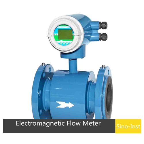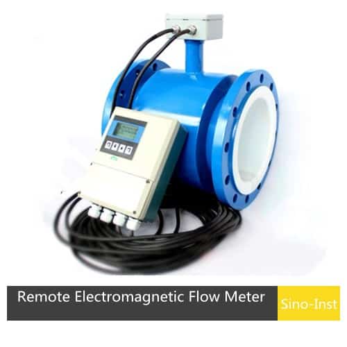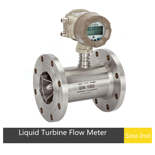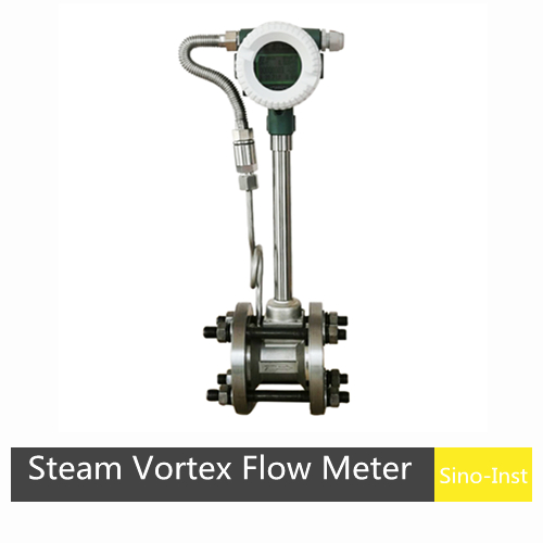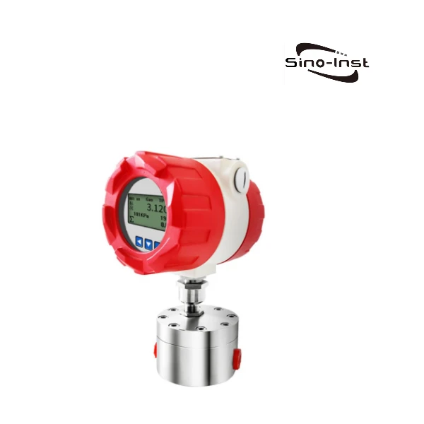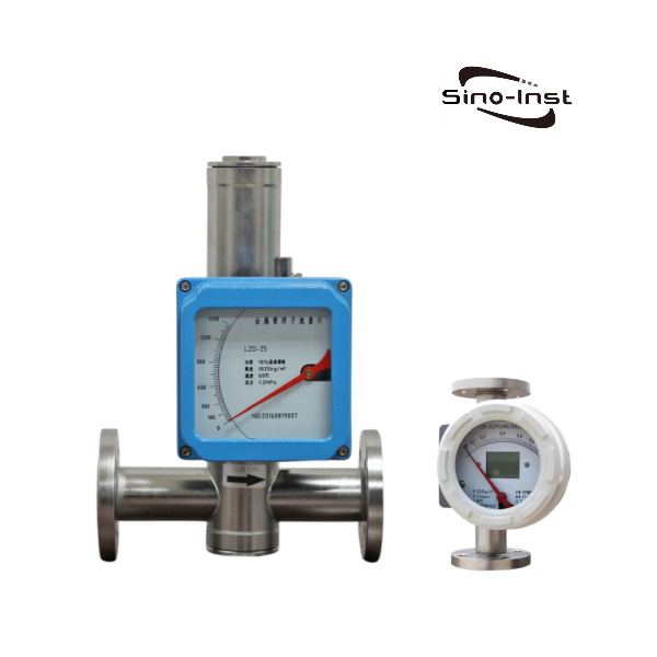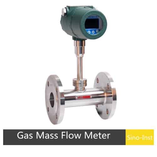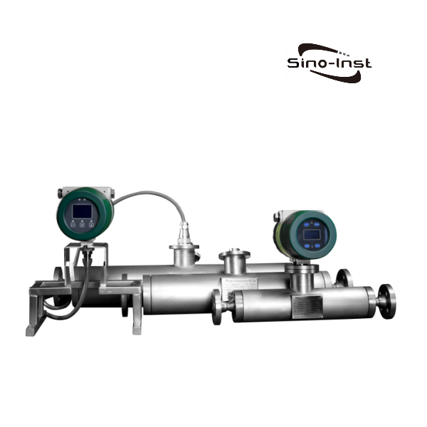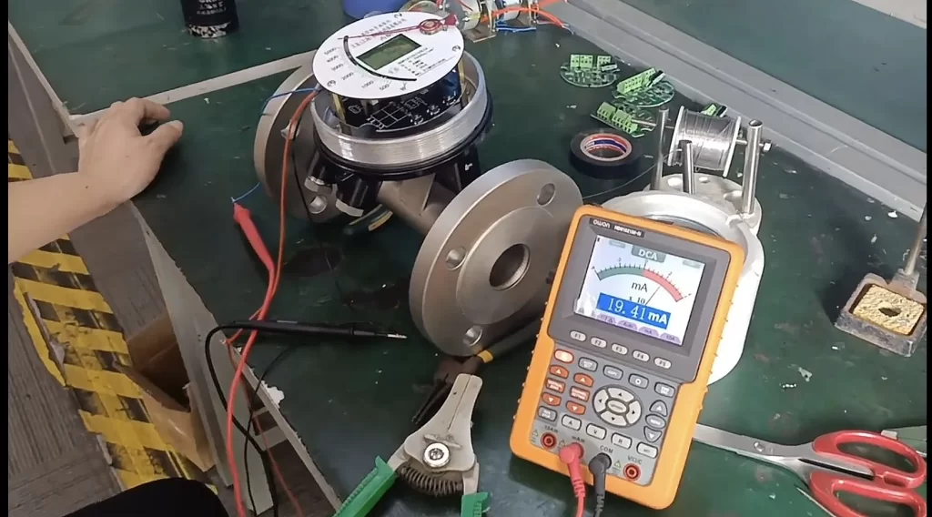
4-20mA flow meter refers to a flowmeter with 4-20mA current signal output function. It measures the volume or mass flow of the fluid and converts it into an electrical signal output. It is used for the automation control of the control system.
Of course, in addition to 4-20mA, there are also pulses, frequencies, switch signals, etc. There are also general selection protocols RS485, HART, etc. It can provide accurate flow data for the control system, thereby realizing the control of fluid flow.
Featured 4-20mA Flow Meters
Introduction to Flow Meter Output Signal
The main function of the flowmeter is to measure the volume or mass flow of the fluid, and then display the flow information. For example, the local display we configured can display instantaneous flow, cumulative flow and other information in detail.
If we need to transmit the flow signal to the control room remotely to provide accurate flow data for the control system, so as to realize the control of the fluid flow. Then the transmission method and protocol of the flowmeter signal are the key to realize this process.
There are mainly the following types of flowmeter signal output:
- Pulse signal
Pulse output refers to the output of measurement parameters, and pulse output provides basic parameters for calibration and remote meter reading.
The pulse is represented by the flashing of the indicator light in the display of some flowmeters, and one flash is a pulse.
- Analog signal
Analog signal output is one of the most common types of flowmeter output signals. It converts the flow into a standard voltage or current signal output through a transmitter, usually 4-20mA or 0-10V.
Analog signal output has the advantages of high precision, good stability and strong anti-interference. It is suitable for occasions where long-distance signal transmission is required.
- Frequency signal output
Frequency signal output is another common flow meter output signal type. It converts the flow rate into a pulse signal output of a certain frequency through a transmitter, usually 1kHz or 10kHz.
Frequency signal output has the advantages of fast response speed and strong anti-interference. It is suitable for occasions that require fast response.
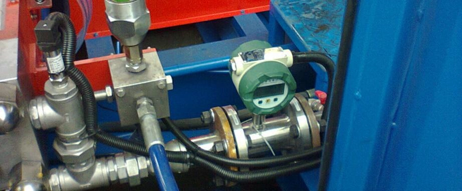
- Switch signal
Switch signal output is a simple flow meter output signal type. It outputs the high and low states of the flow rate through a switch quantity, usually NPN or PNP output.
Switch signal output has the advantages of simple output and easy control. It is suitable for occasions that require simple control.
- Communication protocol
The protocols of flow meter signals include Modbus protocol, HART protocol, and Foundation Fieldbus protocol.
(1). Modbus protocol
Modbus protocol is a commonly used industrial control system communication protocol, which is widely used in the transmission of flow meter signals. Modbus protocol supports multiple transmission methods, including serial port, Ethernet, etc., and has a wide range of applications.
(2). HART protocol
HART protocol is a digital communication protocol that can embed digital signals in analog signals to achieve digital signal transmission. HART protocol can be transmitted through 4-20mA analog signals or through digital communication.
(3). Foundation Fieldbus protocol
Foundation Fieldbus protocol is a digital communication protocol that supports multiple transmission methods, including serial port, Ethernet, etc., and has a wide range of applications. Foundation Fieldbus protocol can achieve communication and control between multiple devices and has high reliability and stability.
The transmission method and protocol of flow meter signals are important components for achieving flow control. Different transmission methods and protocols have their own advantages and disadvantages. It is necessary to select the appropriate method and protocol according to actual needs.
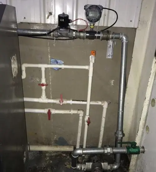
Benefits of Flow Meter 4-20mA Output
- Current signals are suitable for long-distance transmission because they are not affected by the resistance of the wire. However, voltage signals will be divided when the wire itself has resistance, resulting in inaccurate measurement. Generally, the maximum transmission distance of 4~20mA is controlled within 100m. For further distances, it is recommended to use digital signals (485 communication).
- Current signals generally use a two-wire system. Voltage signals generally use a three-wire system. In comparison, the two-wire system saves materials and reduces costs compared to the three-wire system.
- Compared with the more complex on-site working conditions, the anti-interference ability of current signals is stronger than that of voltage signals. Under interfering working conditions, users are advised to choose 4~20A signals.
- The current signal can appropriately exceed the range and output inaccurate signals. For example, a pressure transmitter with a range of 1MPa and an output of 4~20mA can output 24mA when the range is exceeded. The voltage signal is slightly different depending on the power supply. For example, a pressure transmitter with a range of 1MPa and an output of 0~10V cannot output a signal above 9V when the power supply is 9V.
- When the wire materials are different (such as copper, nickel), a magnetic field will generally be generated. In situations where high precision is required, the voltage signal will have errors, but the current signal will not.
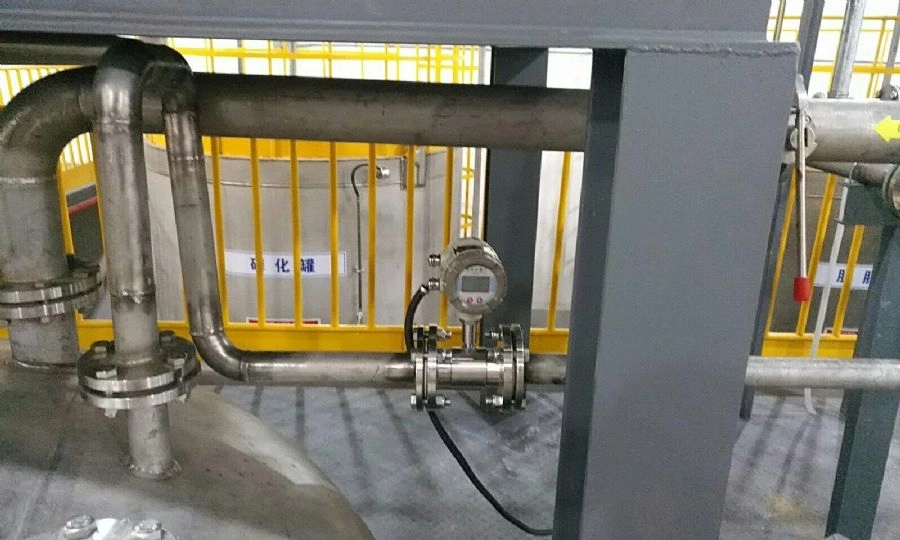
How to calculate the flow range corresponding to the flow meter output of 4-20ma?
The relationship between the flow meter output and the flow rate is:
Flow value / range = (output value – 4) / output range
Among them:
- Range = upper limit of measurement range – measurement start value;
- Output range = upper limit of output – lower limit of output = 16;
- -4 is to remove the output starting point. If you are calculating the output value, don’t forget to add it back.
The flow range is determined by the flow meter specifications. Although some can be modified, they are not normal adjustments. Instead, they are redesigned using the original instrument.
For example, the manufacturer’s nominal value of the DN25 flow meter is 0-3.0m3/h (assuming liquid), you can only measure and set within this range.
For 4-20mA output, the corresponding flow rate (assuming linearity): 4mA corresponds to 0m3/h; 8mA (25%) corresponds to 0.75m3/h (25%); 12mA (50%) corresponds to 1.5m3/h (50%); 20mA (100%) corresponds to 3m3/h (100%).
More Flow Measurement Solutions
- Analog Flow Meters: An Encompassing Guide
- Industrial Hydraulic Flow Meters | Mechanical & Digital
- Approaches To Gas Flow Measurement: Types and Applications Of Gas Flow Meters
- Irrigation Flow Meters-Indispensable for Modern Agriculture and Irrigation
- Ultrasonic Flow Meters: Doppler Effect vs Transit Time
- Doppler Effect Ultrasonic Flow Meters | Sino-Inst
- Hydrogen Flow Meters for Mass and Volume Flow
- Beverage Flow Meters for Flow Monitoring and Quantitative Filling
- Industrial Digital Helium Flow Meters | Mass-Volume Flow
4-20mA flowmeter is the most common type of flowmeter in industry. Sino-Inst produces and supplies various types of 4-20mA flowmeters, including liquid flowmeters, gas flowmeters, solid flowmeters, etc.
If you need to purchase a flowmeter, or have any questions about the 4-20mA signal output of the flowmeter. Please contact our sales engineer!
-1.jpg)
