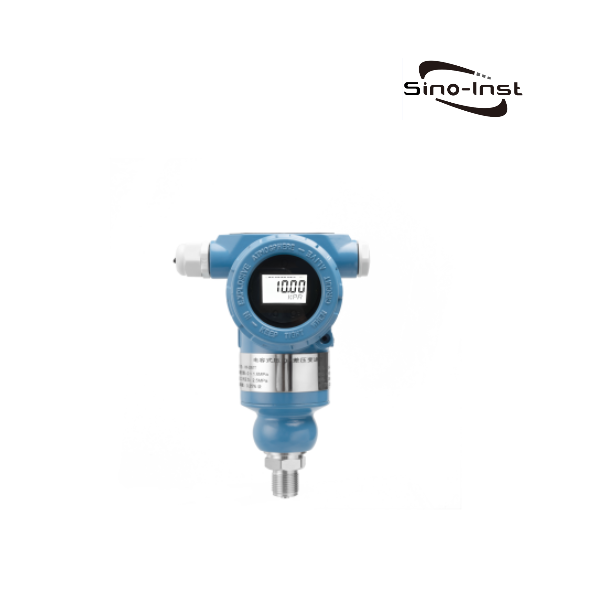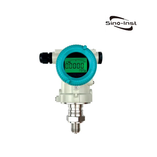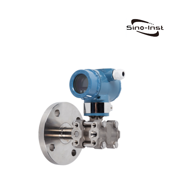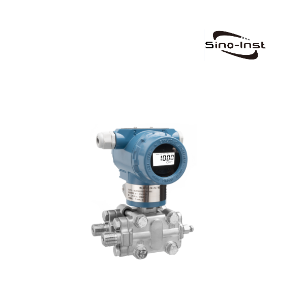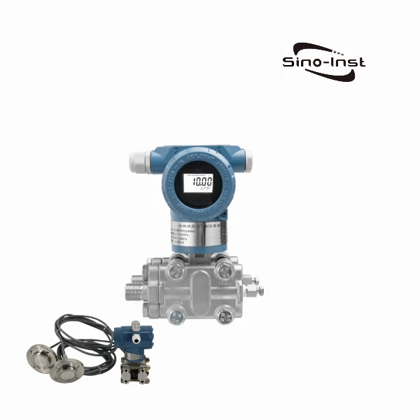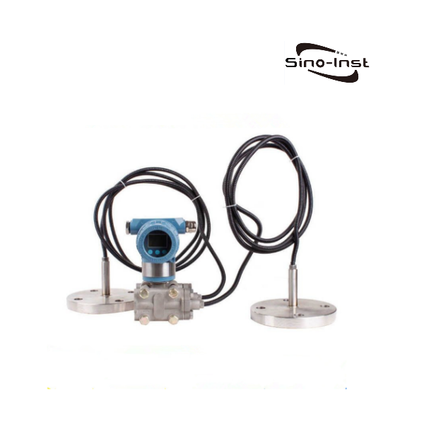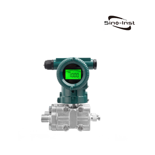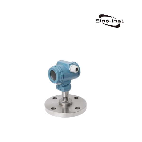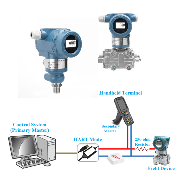
Industrial HART pressure transmitters and differential pressure transmitters support the 4-20mA+ HART protocol. HART (Highway Addressable Remote Transducer) protocol is the most commonly used standard for intelligent field devices in the process control industry.
The HART protocol smart pressure/differential pressure transmitter transmits data through AC digital signals, which uses 4-20mA analog output signals as the carrier. This eliminates the need for additional wires and connectors.
Featured HART Pressure Transmitters and DP Transmitters
What is the HART protocol?
HART (Highway Addressable Remote Transducer) is a communication protocol launched by the American ROSEMOUNT company in 1985 for use between field smart instruments and control room equipment. HART devices provide communication with relatively low bandwidth and moderate response time. After nearly 40 years of development, HART technology has become very mature and has become the global industry standard for smart instruments.

The HART protocol uses FSK frequency shift keying signals based on the Bell202 standard. An audio digital signal with an amplitude of 0.5mA is superimposed on the low-frequency 4-20mA analog signal for two-way digital communication, with a data transmission rate of 1.2kbps. Since the average value of the FSK signal is 0, it does not affect the size of the analog signal transmitted to the control system, ensuring compatibility with existing analog systems. In the HART protocol communication the main variables and control information are transmitted via 4-20mA. If required, additional measurements, process parameters, device configuration, calibration, diagnostic information are accessed via the HART protocol.
Advantages of HART Protocol

What is the Hart protocol for pressure sensors?
Traditional pressure transmitters only provide analog signal 4~20mA current loop output. The intelligent pressure transmitters currently provided by our Sino-Inst all support the 4-20mA+ HART protocol.
The HART protocol allows bidirectional digital communication between sensors and a control system or HART communicator. This makes it possible to transmit device configuration, diagnostic information and more complex measured values in addition to the analog 4-20 mA signal. The HART protocol improves data accuracy, enhances device diagnostic capabilities, and enables remote device management and configuration.
HART pressure transmitters are widely used in the field of industrial control. The main advantages are:
- Facilitate debugging of instruments and control loops.
- HART instruments can provide information about the instrument itself, and debugging personnel can easily understand various information about the instrument from the screen. Including information such as the model of the instrument itself, measurement range, manufacturer, material, station number, etc.
- When debugging the control loop, the debugger can allow the HART communication to have an analog signal output. Through the output of this analog signal, the action of the control loop can be observed to confirm whether the loop is working normally. Using this method to start the alarm or safety interlock system can confirm the system whether it is working properly.
- When the system is running, unexpected shutdowns are sometimes inevitable. In order to reduce unexpected shutdowns, HART communication can be used to allow operators to make correct judgments on the system. HART instruments can verify the output analog signals. By comparing the analog signal output by a certain instrument with the digital signal of the same process of the instrument, it can be judged whether there is a problem.
- Maintenance and management of on-site instruments through the network improves the efficiency of instrument maintenance. First, maintenance personnel can create an instrument profile through information from HART instruments. Secondly, HART instruments can provide status information about the instrument itself to the system. Using HART instrument maintenance personnel reduces the number of trips to the site. If it is found that the instrument has fault information, you can get more detailed fault information from the HART instrument. You can initially determine the fault of the instrument, and then bring the correct tools to the site for troubleshooting, avoiding unnecessary trips.
- Utilizing multiple variable measurement values in HART instruments or adopting multi-hook methods can reduce the number of instruments and save instruments. Generally speaking, HART instruments can provide measurements of four variables, and using these signals can reduce the number of instruments. Generally, HART instruments can only communicate 1 to 2 times per second. However, if 15 instruments are connected to a network segment through multiple connections, the update time is about 10 to 15 seconds.
How do you calibrate a Hart pressure transmitter?
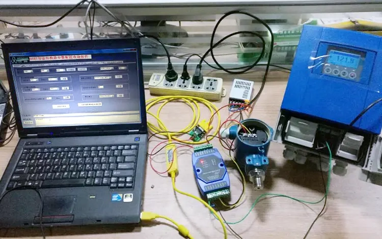
After knowing the principles of the transmitter and the HART protocol, if the instrument is found to be unqualified during the transmitter calibration process, the transmitter can be calibrated and corrected through the HART protocol. Specific steps are as follows:
- Pressure clearing
Here we take a gauge pressure transmitter as an example. Pressure clearing refers to zero clearing when the pressure transmitter is not under pressure. The zero point clearing of the gauge pressure transmitter is carried out when the gauge pressure gauge is only subjected to atmospheric pressure.
- Current loop test
This test can specify that the transmitter fixedly outputs a loop simulation current of a specified current value. Through the ammeter in the loop, we can judge the accuracy of the current output link of the transmitter. If the accuracy is not up to standard, the third step of current adjustment is required. Therefore, generally during the calibration process, the third step of current adjustment will be performed directly.
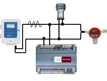
Because during the current adjustment process, it is also necessary to test the zero point (4mA) and range (20mA) of the transmitter. The handheld communicator does not have a flow measurement function, so if a handheld communicator is used during current loop testing and current adjustment, an ammeter needs to be inserted in the loop (the higher the accuracy, the better).
- Current adjustment
When there is a large difference between the specified current value and the measured current value in the loop test, current adjustment is required. There are only two points for current adjustment: zero point and gain (range), which are 4mA and 20mA. The current ratio between the two points is linear.
Generally, when calibrating the transmitter, if you do not perform a standard pressure source test, you usually perform “pressure clearing” and “current adjustment” to restore the accuracy of the transmitter.
- Sensor adjustment
If the transmitter measurement value is still inaccurate after “pressure clearing” and “current adjustment”, the sensor needs to be adjusted.
Sensor adjustment is an adjustment made when the pressure value displayed by the transmitter test does not match the standard value and exceeds the error.
For example: after a pressure change of (0~6) MPa has been “pressure cleared” and “current adjusted”, it still fails to pass the calibration, and the sensor of the transmitter needs to be adjusted. That is, let the 6MPa point of the transmitter correspond to the 6MPa point of the standard table, so the fourth step of adjustment requires a standard pressure source.
- Adjust the pressure and current accordingly.
Adjustments should only be made if the transmitter’s pressure measurement does not correspond to the current output value. This adjustment also requires a standard pressure source. The specific method is to apply pressure on the transmitter, and the pressure is the upper and lower limits of the actual range of the transmitter. Assign the corresponding pressure values to the upper and lower limits of the transmitter respectively. In this way, the actual applied pressure corresponds linearly to (4~20) mA. In other words, only the corresponding relationship between the pressure value and the current value is adjusted.
This calibration adjustment is equivalent to the [SPAN] and [ZERO] buttons on the transmitter. Since only the current value is changed, the value is accurate on the SCADA system. But the on-site display may still be outside the allowable error. At the same time, the linear relationship between transmitter pressure and current rarely changes. Therefore, the corresponding adjustment of pressure and current is generally not performed, and “sensor adjustment” is performed directly.
Read more about: How to calibrate a pressure transmitter? How often?
More Pressure Measurement Solutions
Industrial Pressure Transmitters: 7 Sensor Principles and 4 Main Types!
Pipe Flow vs Pressure – Relationship & Calculate Tools
Pressure Transducer Troubleshooting: Expert Insights & Tips
Fluid Pressure Guide: Static Pressure Vs. Dynamic Pressure Vs. Total Pressure
Steam Pressure Sensor/transducer for Industrial Steam Measurement
How to Choose the Right Oil Pressure Transmitter for Your Application
Gauge Pressure vs Absolute Pressure | Differences and Relationships
When the smart transmitter is working, it will transmit analog signals (such as DC 4~20mA) to the PLC. The HART digital signal is superimposed on the 4~20mA output, which is why the handheld terminal can be adjusted and verified online.
We, Sino-Inst, are a professional manufacturer of HART pressure transmitters. We supply more than 10 types of HART pressure transmitters and differential pressure transmitters. In addition to HART pressure transmitters, there are also pressure transmitters with RS485 protocol. Support 4-20mA + RS485 dual signal output.
Our industrial pressure transmitters are widely exported to various countries and used in various industries. If you need to purchase Industrial HART Pressure Transmitters and DP Transmitters, or have related questions, please feel free to contact our engineers!
-1.jpg)
