Guided Wave Radar Level Transmitter Installation Guide and Troubleshooting
Only a reasonable Guided Wave Radar Level Transmitter Installation can ensure long-term reliable and accurate measurement. And paying attention to the details during installation can avoid many troubles during use.
Guided Wave Radar Level Transmitter is a contact type liquid level measuring instrument. It can measure liquids, particles and slurries and is not affected by medium changes, temperature changes, inert gases, steam, dust, foam, etc. Suitable for acid and alkali storage tanks, slurry storage tanks, solid particles, small oil storage tanks and other complex occasions.
You can first check about our Guided Wave Radar Level Transmitter Working Principle, Models And Technical Parameters
Guided Wave Radar Level Transmitter Installation Guide
Make sure the cable or rod does not contact internal obstructions throughout the entire Guided Wave Radar Level Transmitter range. Therefore, the facilities inside the tank should be avoided as much as possible during installation. Such as: human ladders, limit switches, heating equipment, brackets, etc. Also note that cables or rods must not intersect with the feed flow. The following installation guidelines apply to cable and rod measurements of solid powders or liquids.
Notes when installing Guided Wave Radar Level Transmitter:
- The highest material level must not enter the measurement blind zone;
- The instrument must be kept at a certain distance from the tank wall;
- The instrument should be installed so that the direction of the cable or rod is perpendicular to the surface of the medium being measured as much as possible.
- Instruments installed in explosion-proof areas must comply with national installation regulations for explosion-proof hazardous areas. The intrinsically safe housing is made of aluminum. Intrinsically safe instruments can be installed in places with explosion-proof requirements, and the instrument must be connected to the ground.
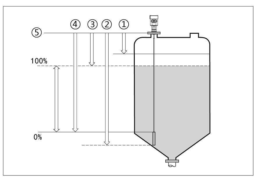
Measurement reference plane is the sealing surface of the thread.
- Blind Range (Menu 1.9)
- Cable Length (Menu 1.8)
- Max.Measurement Range (Menu 1.2)
- Min.Measurement Range (Menu 1.1)
- reference Plane
Installation location:
The installation instructions here are suitable for cable and rod measurement of solid powders or liquids.
- Try to stay away from the discharge port and feed port.
- The metal can does not touch the wall or bottom of the can within the entire measuring range.
- It is recommended to install it at 1/4 or 1/6 of the diameter of the silo, and the minimum distance from the tank wall is 1/10 of the measuring range.
- The minimum distance between the cable or rod probe and the tank wall is ≥300mm.
- The bottom of the probe is ≥30mm from the bottom of the tank.
- The minimum distance between the probe and the obstacles in the tank is ≥200mm.
- If the bottom of the container is tapered, the center of the tank top can be installed.
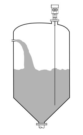
The following is an installation diagram of a Rod Guided Wave Radar Level Transmitter, which is mainly used for liquid level measurement.
- Can measure any medium with dielectric constant ≥1.8.
- Generally used to measure media with a viscosity ≤500cst and which are not prone to adhesion.
- The maximum range of rod radar can reach 6 meters.
- It has strong penetration ability for steam and foam, and the measurement is not affected.
- For liquid measurement environments with large foam, single-rod guided wave radar level meters should be selected for measurement.
The picture below shows the installation diagram of a dual-cable guided wave radar liquid level transmitter, which is mainly used for measuring the level of low dielectric constant liquids and low dielectric constant light solid powder materials.
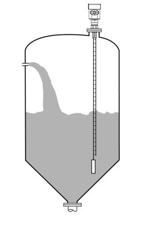
- Liquids and light solid powders with relatively small dielectric constants can use the dual-cable measurement method to ensure good and accurate measurement.
- Can measure any medium with dielectric constant ≥1.6.
- Generally used to measure media with a viscosity ≤500cst and which are not prone to adhesion.
- The maximum range of the dual-cable radar level meter can reach 30 meters.
installation method
Proper installation can ensure long-term reliable and accurate measurement of the instrument:
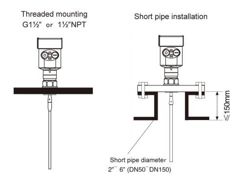
Guided Wave Radar Level Transmitter can be connected by thread, the length of the thread should not exceed 15mm, and can also be installed on a short pipe.
When the diameter of the installed short pipe is 2″ to 6″, the height of the installed short pipe should be ≤100mm (the shorter the length of the thread and the short pipe, the more stable the measurement). If the short pipe is long, ideally the short pipe should be cut short, or the cable probe should be fixed at the bottom and an insulating centering bracket should be used to prevent the cable probe from contacting the end of the short pipe.
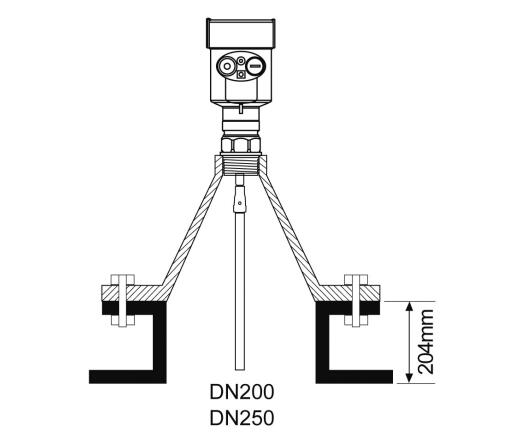
Installation in short pipe of DN200 or DN250:
When the Guided Wave Radar Level Transmitter needs to be installed on a short pipe with a diameter greater than 200mm, the inner wall of the short pipe will generate echoes, which will cause measurement errors when the dielectric constant of the medium is low.
Therefore, for a short pipe with a diameter of 200mm or 250mm, a special flange with a “horn interface” needs to be selected.
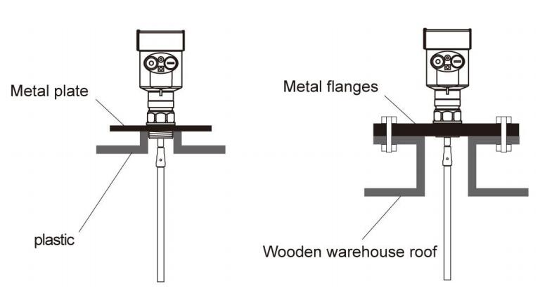
Precautions for installation on plastic tanks:
Whether it is a cable or rod type, if the guided wave radar is to work properly, the process connection surface should be metal. When the guided wave radar is installed on a plastic tank, if the top of the tank is also plastic or other non-conductive material, the instrument needs to be equipped with a metal flange. If threaded connection is used, a metal plate is required.
Optimization of interference:
Interference echo suppression: The software can suppress interference echoes to achieve ideal measurement results.
Bypass tube and waveguide (only applicable to liquid) For viscosity not greater than 500cst, bypass tube or waveguide can be used to avoid interference.
Installation of low dielectric constant liquids:
For media with a dielectric constant greater than 1.3, a viscosity ≤500cst and which is not prone to adhesion, the guided wave radar can be installed in the waveguide for measurement. Its characteristics are as follows:
- Excellent reliability and high precision;
- It can be used for any medium with dielectric constant ≥1.3, and the measurement has nothing to do with the conductivity of the medium;
- Obstacles in the tank and the size of the short pipe do not affect the measurement;
Measurement of corrosive media:
If corrosive media is measured, rod-type or cable-type probes with PTFE or PFA sleeves can be used for measurement.
Installation on horizontal and vertical tanks:
- The rod probe can be up to 6 meters long. For tanks with a measurement distance of more than 6 meters, a 4mm cable probe can be used;
- The installation and fixing methods are the same as for solid powder silo measurement;
- The distance from the tank wall is greater than or equal to 300mm, and the probe must be prevented from contacting the tank wall;
- When selecting the probe length, note that the distance between the bottom of the probe and the bottom of the tank is greater than 30mm;
- If there are many obstacles in the tank or are too close to the probe sensor, a waveguide can be installed for measurement;
Special instructions for installation:
For guided wave radars with too long cables used in the field, the excess part of the cable needs to be intercepted to ensure correct measurement. The cable cannot be knotted, wound, or attached to other objects.
When cutting the cable, first cut off the power supply of the instrument, remove the cable, and remove the screws on the weight. Cut it from the bottom of the cable. After cutting, you need to reinstall the weight. After the instrument is installed, turn on the power again. and reset the parameters.
For cable-type guided wave radar with casing, when the cable is too long, it is not allowed to intercept it by itself and must be returned to the original factory for interception.
For guided wave radar level gauges installed in waveguides, an insulating bracket must be used to fix the radar probe. Ensure that the radar probe (rod/cable) is concentric with the waveguide, otherwise the radar waveform will oscillate and affect the measurement.
Precautions:
Guided wave radars installed in waveguides generally use rod-type probe sensors. During installation, an insulating concentric bracket should be installed on the rod-type probe to ensure that the rod-type probe and the waveguide are concentric. Otherwise, strong false echoes will be generated.
When the measurement range exceeds the maximum measurement range of the rod probe, a guided wave radar with a cable probe should be used. At this time, the diameter of the waveguide should be greater than or equal to 6″ (DN150). Otherwise, strong false echoes will be generated.
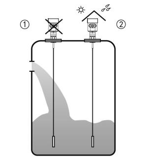
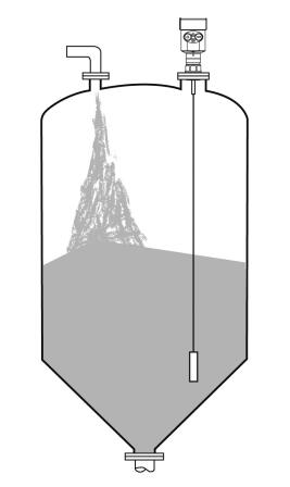
- Wrong installation: Do not install the instrument above the incoming material flow. The cable or rod should avoid the material opening;
- Correct installation: Note: Sunshade and rainproof measures should be taken when installing outdoors;
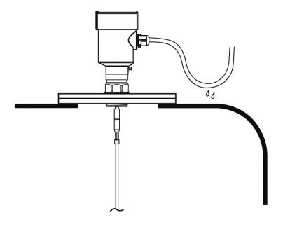
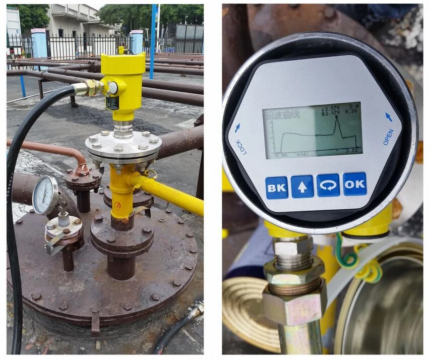
For instruments installed outdoors or in humid rooms and on refrigerated or heated tanks. To prevent moisture, the cable gland should be tightened and the cable should be bent downwards at the cable entry. As shown in the picture.
Guided Wave Radar Level Transmitter Troubleshooting
How to deal with probe scarring and frequent failures
The first method is to raise the installation position of the Guided Wave Radar Level Transmitter probe. However, sometimes when the installation conditions are limited and cannot be improved, the method of interlocking the liquid level measurement value with the pump of the tank should be used to solve this problem. Reduce the maximum liquid level setting value by about 0.5m. When the liquid level reaches the maximum value, the discharge pump can be stopped or started.
About the effect of foam on measurements
Dry foam and wet foam can reflect the radar wave back from the guided wave radar level gauge without affecting the measurement.
Neutral foam will absorb and diffuse radar waves, thus seriously affecting the reflection of echoes or even causing no echoes at all.
When the medium surface is thick and thick foam, the measurement error is large or cannot be measured. In this working condition, radar level gauge has no advantage, which is a limitation of its application.
Treatment of antenna scarring
Hanging materials with a small dielectric constant have no effect on the measurement in the dry state, while hanging materials with a high dielectric constant have an impact on the measurement.
It can be purged with compressed air (or flushed with clean water), and the cooled compressed air can reduce the temperature of the flange and electrical components. Alkaline scabs can also be cleaned with acidic cleaning solutions, but level measurement cannot be performed during cleaning.
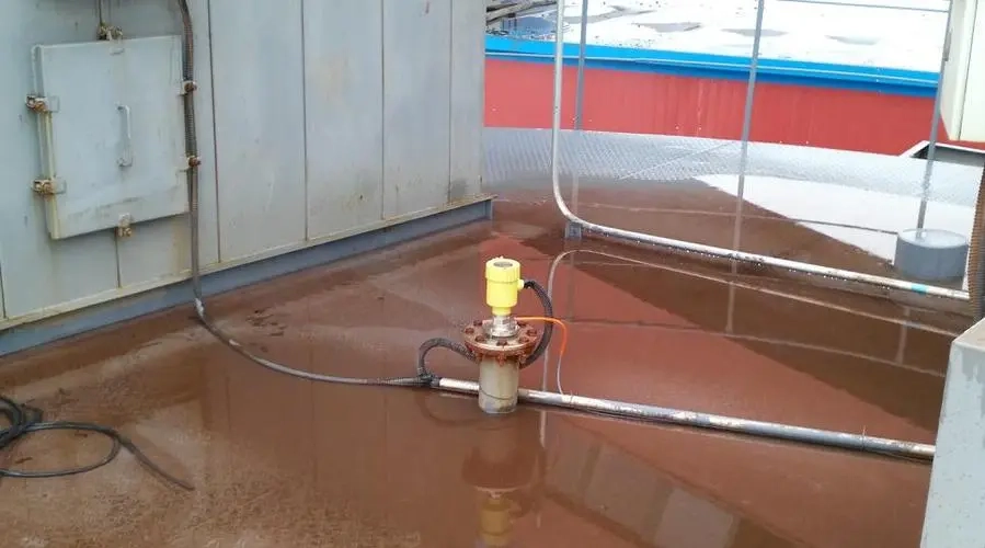
Corresponding treatment methods for flooding
The solution to this problem is to change the Guided Wave Radar Level Transmitter to a waveguide type measurement. The waveguide-type Guided Wave Radar Level Transmitte is still installed at the original opening, and the waveguide is about 0.2m higher than the exhaust pipe.
In this way, even if the liquid slurry overflows from the exhaust pipe under severe working conditions, the liquid level gauge antenna will not be submerged by the slurry. And it avoids the interference of the stirrer eddy current and the large amount of steam emerging from the probe. The damage to the probe is reduced, and the focusing effect of the waveguide is good. The received radar wave signal is stronger and good measurement results are achieved.
Using the waveguide measurement method can improve the meter measurement conditions and improve the meter measurement performance, which has high promotion and application value.
More Featured Level Measurement
- Difference Between Radar and Guided Wave Radar Level Transmitter
- Hydrostatic Level Measurement-Liquid Level Measurement with Pressure Sensors
Guided Wave Radar Level Transmitter is a contact type liquid level measuring instrument. It uses high-frequency microwave pulse technology and can measure the liquid level of liquids, powders and particles of various materials. It has the advantages of high precision, good reliability and wide application range. Therefore, it is widely used in industry, chemical industry, food, pharmaceutical and other fields.
Understanding the Guided Wave Radar Level Transmitter Installation Guide and Troubleshooting in advance can help you better understand the product performance of the guided wave radar level transmitter before purchasing, and at the same time make a judgment on the applicability.
If you need to purchase Guided Wave Radar Level Transmitters, or have related technical questions, please feel free to contact us.

Zhang Wei, possesses 20 years of experience as an automation instrumentation engineer, specializing in the research, design, installation, commissioning, and maintenance of automation instruments.
Face to various instrument communication protocols (such as Modbus, Profibus, etc.), with solid hardware circuit design and software programming skills (proficient in C language and PLC programming). Has extensive project experience; projects he has led and participated in have all achieved outstanding results, improving product accuracy, reducing costs, and increasing production efficiency.
Possesses excellent communication and coordination skills and a strong team spirit, enabling him to quickly respond to customer needs and provide high-quality automation instrumentation solutions.