Best Technology Guide to Ultrasonic Flow Meters.
An ultrasonic flow meter is a volumetric flow meter that measures the flow rate of a medium based on the effect of the flowing medium on the ultrasonic velocity or ultrasonic pulse. There are two types of ultrasonic flow meter technologies: Doppler and transit-time.
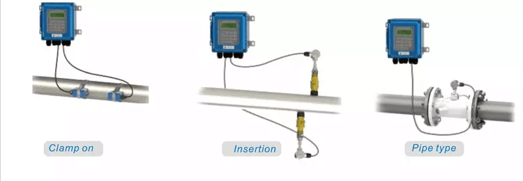
We will mainly introduce and analyze ultrasonic flow meters for measuring liquids. There are non-intrusive type, insertion type, pipeline type, etc.
What is an Ultrasonic Flow Meter?
An ultrasonic flow meter refers to a flowmeter developed based on the principle that the propagation speed of ultrasonic waves in a flowing medium is equal to the vector sum of the average flow velocity of the measured medium and the speed of the sound wave in a stationary medium. It is mainly composed of a transducer and a converter. There are different types such as the Doppler method, the time difference method, the beam offset method, the noise method and the correlation method.
For liquid media, Doppler ultrasonic flowmeters and transit-time ultrasonic flowmeters are commonly used in industrial processes.
Know more about Ultrasonic flow meter – Wikipedia
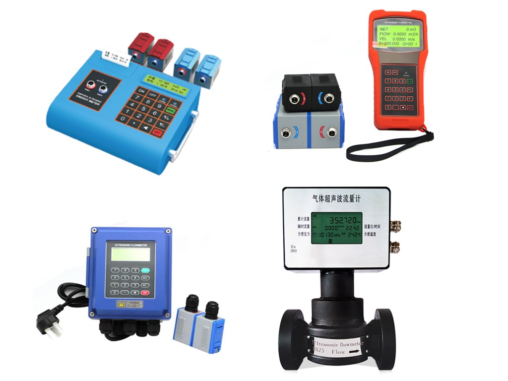
Featured Ultrasonic Flow Meters

Features of Ultrasonic Flow Meters
Ultrasonic flowmeter is a non-contact instrument that has been applied with the rapid development of integrated circuit technology in the past ten years. It is suitable for measuring fluids that are not easy to contact and observe, as well as large pipe flow.
- Simple structure, easy to install and use.
- Energy saving. No additional resistance is generated and no pressure loss.
- Suitable for difficult-to-measure media and large pipelines.
- Simple structure, convenient installation, use and maintenance.
- Easy to maintain. The inspection parts are easy to repair and replace, and do not need to be cut off (except for the built-in type).
- The unique signal digital processing technology makes the instrument’s measurement signal more stable, strong anti-interference ability and more accurate measurement.
- Non-mechanical transmission parts are not easily damaged, maintenance-free, and long life.
- The circuit is more optimized and highly integrated; low power consumption and high reliability.
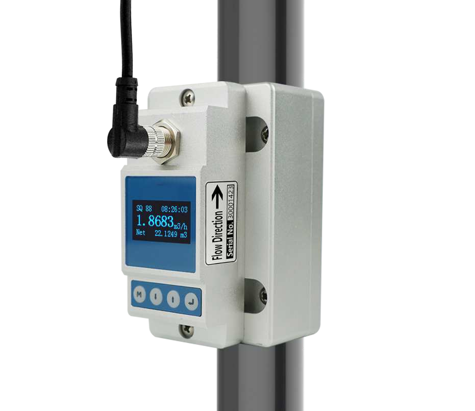
- Intelligent standard signal output. Friendly man-machine interface, multiple secondary signal outputs for your choice.
- Pipe section type small diameter measurement is economical and convenient. And the measurement accuracy is high.
Types of Ultrasonic Flow Meters
In terms of measurement principle, ultrasonic flowmeters can be categorized into transit-time ultrasonic flowmeters and Doppler ultrasonic flowmeters.
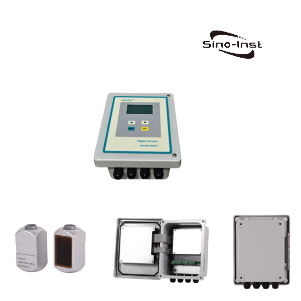
In terms of structure, ultrasonic flowmeters generally consist of sensors and transmitters (main unit). They can also be classified according to the different forms of sensors and transmitters.
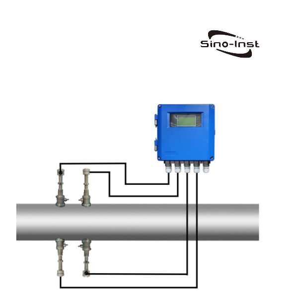
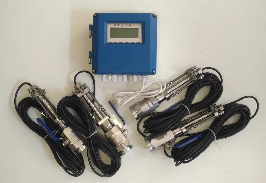
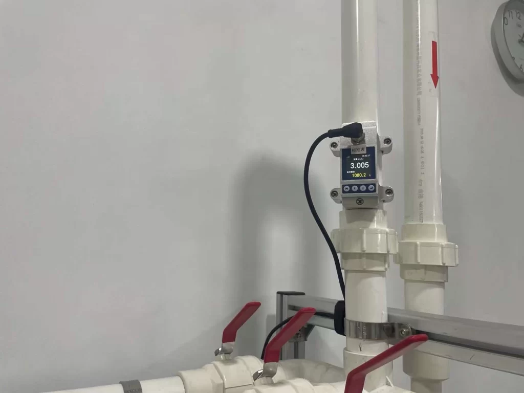
- Insertion-type ultrasonic flowmeter: can be installed and maintained without stopping production. The ceramic sensor is used for non-stop installation using a special drilling device. Generally, it is mono measurement. To improve the measurement accuracy, three channels can be selected.
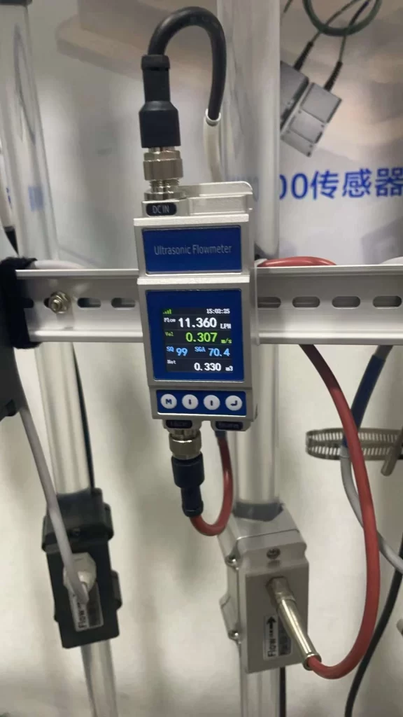
- Pipe segment type ultrasonic flowmeter: needs to cut the pipeline to install, but future maintenance can be stopped. Choice of mono or tri-channel sensors.
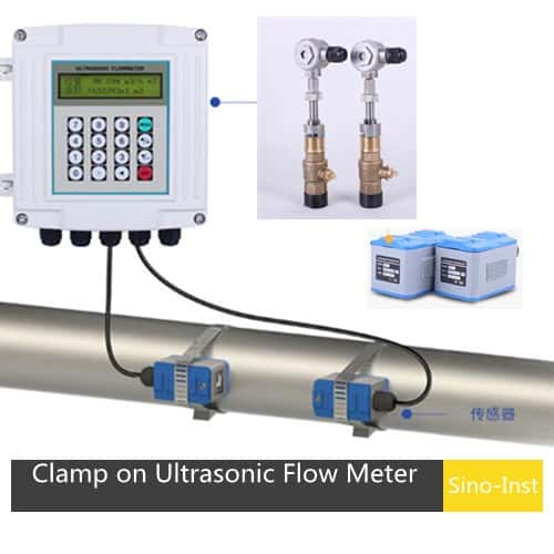
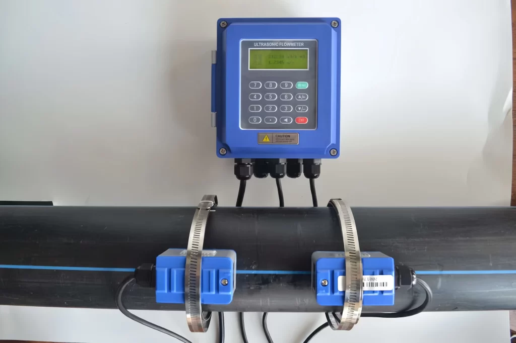
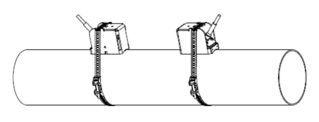
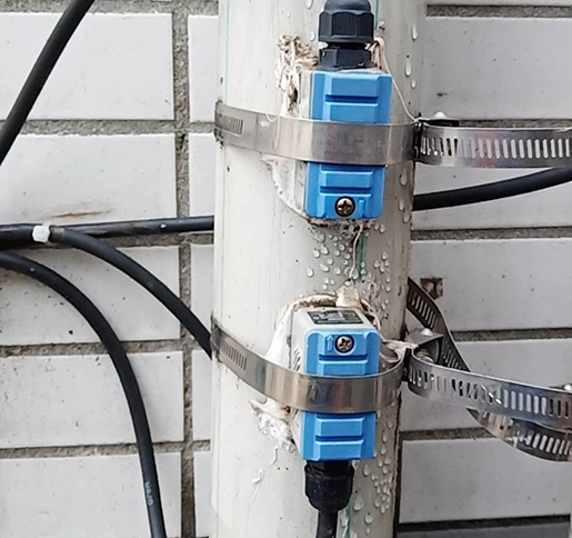
- External clamp-on type ultrasonic flowmeter: can perform fixed and mobile measurement. Use special coupling agent (silicone rubber cured at room temperature or high-temperature long-chain polymer grease) for installation, and the pipeline will not be damaged during installation.
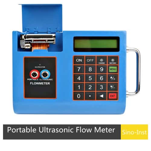
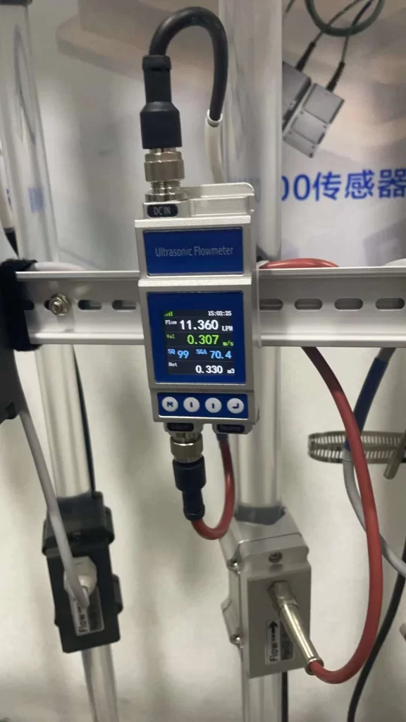
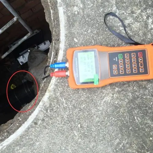
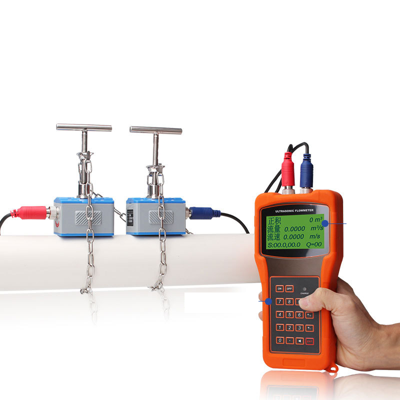
- Portable ultrasonic flowmeter: portable use, built-in rechargeable lithium battery, suitable for mobile measurement, with magnetic sensor.
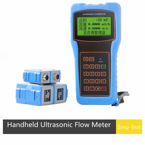
- Hand-held ultrasonic flowmeter: small size, light weight, built-in rechargeable lithium battery, handheld use, equipped with magnetic sensors.
Ultrasonic Flow Meter Work Principle
Ultrasonic flowmeters use sound waves to determine the velocity of a fluid flowing in a pipe. Their working principles are mainly divided into two types: Doppler and time difference.
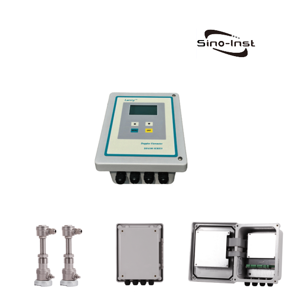
Doppler ultrasonic flowmeter:
At no flow conditions, the frequencies of an ultrasonic wave are transmitted into a pipe. And its reflections from the fluid are the same.
Under flowing conditions, the frequency of the reflected wave is different due to the Doppler effect. When the fluid moves faster, the frequency shift increases linearly. The transmitter processes signals from the transmitted wave and its reflections to determine the flow rate.
Read more about: doppler effect ultrasonic flow meters advantages
Transit time ultrasonic flowmeter:
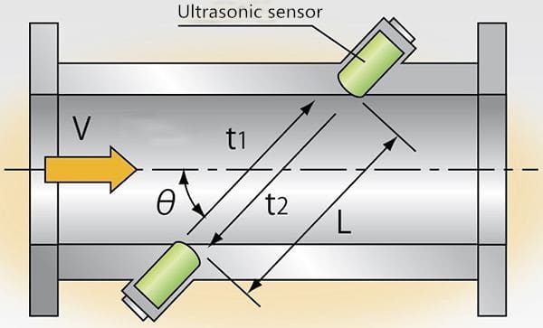
Transit time ultrasonic flowmeters send and receive ultrasonic waves between transducers in both the upstream and downstream directions in the pipe.
At no flow conditions, it takes the same time to travel upstream and downstream between the transducers.
Under flowing conditions, the upstream wave will travel slower and take more time than the (faster) downstream wave.
When the fluid moves faster, the difference between the upstream and downstream times increases. The transmitter processes upstream and downstream times to determine the flow rate. They represent about 12% of all flowmeters sold.
Principles
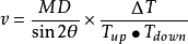
When the ultrasonic beam propagates in a liquid, the flow of the liquid will cause a small change in the propagation time. And the change in the propagation time is proportional to the flow velocity of the liquid. The relationship is as follows:
Which:
θ is the angle between the sound beam and the direction of liquid flow.
M is the number of linear propagations of the sound beam in the liquid.
D is the inner diameter of the pipe.
Tup is the propagation time of the sound beam in the positive direction.
Tdown is the propagation time of the sound beam in the reverse direction.
ΔT = Tup –Tdown
Let the speed of sound in a stationary fluid be c. The velocity of the fluid flow be u. And the propagation distance be L.
When the sound wave is in the same direction as the fluid flow (that is, in the downstream direction), its propagation velocity is c + u.
Otherwise, the propagation velocity is cu .
Place two sets of ultrasonic generators and receivers (T1, R1) and (T2, R2) at two places separated by L.
When T1 transmits ultrasonic waves in the forward direction and T2 in the reverse direction.
The time required for the ultrasonic waves to reach the receivers R1 and R2 is t1 and t2, then:
t1 = L / (c + u); t2 = L / (c-u)
Because in industrial pipelines, the velocity of the fluid is much smaller than the speed of sound, that is, c >> u, the time difference between the two is ▽ t = t2-t1 = 2Lu / cc.
It can be seen that when the sound wave propagates in the fluid c When known, the flow velocity u can be obtained by measuring the time difference ▽ t, and the flow rate Q can be obtained.
The method of flow measurement using this principle is called the time difference method. In addition, phase difference method and frequency difference method can be used.
Advantages and Disadvantages of Ultrasonic Flow Meter
Advantages
- This technology can be very accurate and is used for custody transfer (meaning accounting accurately for an expensive fluid) of natural gas and petroleum liquids.
- There is no pressure loss. A type that can perform detection from the outside of piping is available.
- Ultrasonic flowmeters are available in sizes to 72 inches and larger.
- High turndown (can read low as a percentage of the full scale or top reading), handles high pressures, is repeatable (consistent), handles extreme temperatures, can be used clamped to the outside of a pipe without penetration, is low maintenance, highly reliable and self–diagnosing.
- Ultrasonic flowmeters do not obstruct flow so they can be applied to sanitary, corrosive and abrasive liquids.
- Some ultrasonic flowmeters use clamp-on transducers that can be mounted externally to the pipe and do not have any wetted parts.
- Temporary flow measurements can be made using portable ultrasonic flowmeters with clamp-on transducers.
- Clamp-on transducers are especially useful when piping cannot be disturbed, such as in power and nuclear industry applications.
- In addition, clamp-on transducers can be used to measure flow without regard to materials of construction, corrosion, and abrasion issues.
Disadvantages
- A long section of straight pipe is required.
- Liquids that have a large solid content will cause malfunctions.
- Measurement is not possible when there are many air bubbles.
- High cost.
- Sensitivity to stray process vibrations, problems with pipe diameter change due to buildup and clamp-on units have lower accuracy.
- The use of clamp-on transducers introduces additional ultrasonic interfaces that can affect the reliability and performance of these flowmeters.
- In particular, if not properly applied and maintained, attenuation of the ultrasonic signal can occur at the interfaces between the clamp-on transducers and the outside pipe walls, and between the inside pipe walls and the fluid.
Applications
Ultrasonic flowmeters have found widespread applications in various fields:
Read more about: Quick Guide: Clamp on Ultrasonic Flow Meter Installation
How to select a clamp-on ultrasonic flow meter?
Before ordering, the following questions must be considered. With answers to the following questions we can select the appropriate flow device and ship it to your location.
- What are the pipe sizes of the liquids that are going to be measured?
- What is the minimum and maximum process temperature of the application?
- Do you require a portable battery-operated unit or a permanent fixed flow monitor powered by mains?
- What are the output requirements? E.g. analog, digital, pulse?
- What is the minimum and maximum flow rate for the flow meter?
- What is the minimum and maximum flow velocity?
- Is there a length of straight pipe away from bends and pipe disturbances?
- Is the pipe always filled with liquid?
FAQ
Technical Support
- Flowmeter Calibration & Recalibration
- Thermal Mass Flow Meter Technology
- Coriolis Mass Flow Meter Technology
- Differential Pressure Flow Meter Technology
- Vortex Flowmeter Technology
- Turbine Flowmeter Technology
- Magnetic Flowmeter Technology
Home » Technologies » Ultrasonic Flow Meter Technology
Sino-Inst is a Professional ultrasonic flowmeter manufacturer and supplier from China. Sino-Inst offers over 10 ultrasonic flow meter products.
Sino-Inst’s ultrasonic flow meters service for industrial applications. Like: Cooling water, industrial gas, corrosives and brine, chemical processing, mining. Wastewater, energy, electronics, laboratories, medical, and many other industries.
A wide variety of ultrasonic flow meter options are available to you, such as free samples, paid samples. If you need to purchase ultrasonic flow meters or have related technical questions, please feel free to contact us.
Wu Peng, born in 1980, is a highly respected and accomplished male engineer with extensive experience in the field of automation. With over 20 years of industry experience, Wu has made significant contributions to both academia and engineering projects.
Throughout his career, Wu Peng has participated in numerous national and international engineering projects. Some of his most notable projects include the development of an intelligent control system for oil refineries, the design of a cutting-edge distributed control system for petrochemical plants, and the optimization of control algorithms for natural gas pipelines.