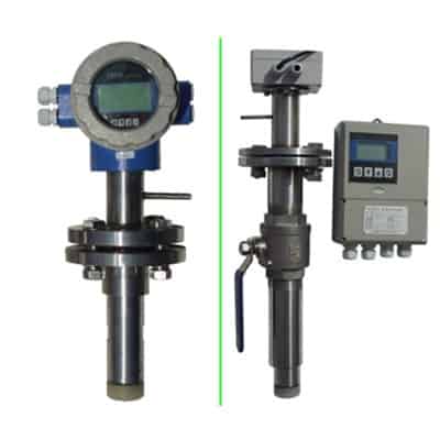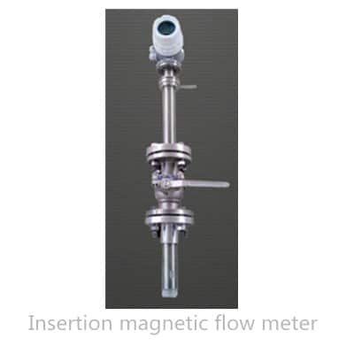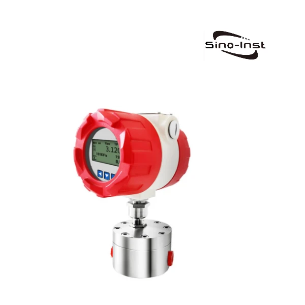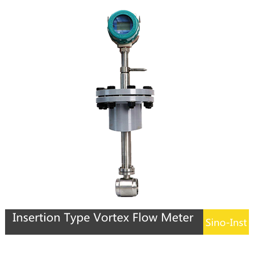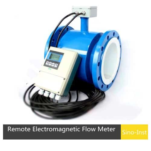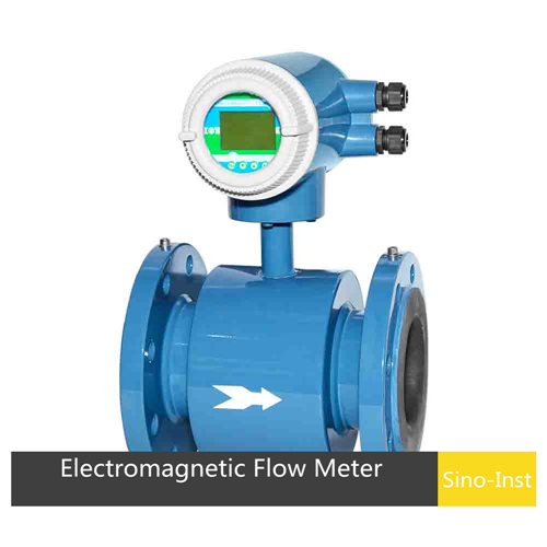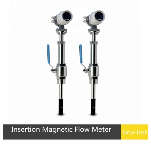
An insertion magnetic flow meter is a flow meter based on Faraday’s law of electromagnetic induction. It is primarily used to measure the volumetric flow rate of conductive liquids in large-diameter closed pipes. It can be installed under pressure, allowing installation without shutting off the water supply. This provides a novel method for measuring and installing liquid flow.
| NO. | SI-Magnetic Water Flow Meter |
| T/T, PayPal | T/T, Paypal |
| Product Origin | China |
| Shipping Port | International Express |
| Lead Time | 3-5 days after payment received |
Features
HOT TAP INSTALLATION
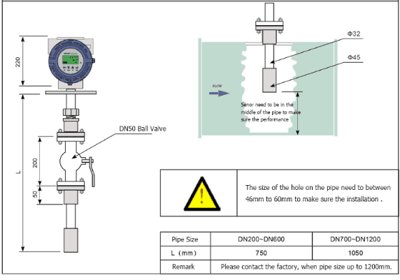
For applications where the Insertion magnetic flow meter will be installed in pressurized pipes, use the optional Hot Tap Installation Hardware Kit.
It includes a branch outlet, close nipple and 1-1/4″ full port ball valve.
INSTALLATION IS EASY
The Insertion Magmeter installs in the pipe through a full port ball valve so the sensor can be easily retracted without having to shut down flow or drain the system. The insertion depth is adjustable according to the pipe diameter. An insertion depth gage is supplied with each flowmeter.
NO PRESSURE DROP
The sensor structure of the electromagnetic flowmeter is relatively simple, and it is one of the flowmeters with the lowest energy consumption in the flowmeters. There are no moving parts in the measuring tube and no throttling part that blocks the flow of fluid and does not cause any additional pressure loss when the fluid passes through the flow meter.
Insertion Magnetic Flow Meter Specifications
| Transmitter | ||
| Working power supply | AC110V~AC245V | |
| DC24V | ||
| Output Signal | Analog output | 4-20mA |
| Pulse output | Hz | |
| Communication | RS-485Optional RS232, M-BUS, HART) | |
| Power consumption | 10W (matching power consumption) | |
| Usage environment | Ambient temperature | -20~+60℃ |
| Storage temperature | -20~+40℃ | |
| Ambient humidity | 5%~90% | |
| Display content | Instantaneous flow | 4 digits |
| Cumulative total | 8 digits | |
| Flow rate | 4 digits | |
| Protective level | IP65 | |
| Casing material | Silicon aluminum alloy | |
| Sensor | ||
| Measurable pipe diameter | DN100~DN3000 | |
| Probe material | 304 stainless steel | |
| Probe structure | Stainless steel/PTFE lining | |
| Electrode material | 316L stainless steel | |
| Medium temperature | One-piece | <70℃ |
| Pressure level | Split type | <120℃ |
| Connection method | ≤1.6MPa | |
| Protection level | Simple type | Flange connection |
| With ball valve insert type | With welded short pipe | |
| Large ball valve optional | Flange connection | |
| Protection level | One-piece type | IP65 |
| Split type | IP65 (IP68 submersible type) | |
| Accuracy level | Measurement error | |
| Flow rate | 0.5~10m/s | ±1.0~±1.5% of the range (calibration can reach ±1.0%) |
| 0.1~0.5m/s | ±1.5% of the range (40%~100% of the full range) | |
| 0~0.1m/s | ±2.0% of the range (40%~100% of the full range) | |
| If the user has special requirements for accuracy, the accuracy can reach ±1% of the measured value within a certain working range. | ||
| Flow Range | |||||||
| Diameter | Flow range | Pressure | Diameter | Flow range | Pressure | ||
| Flow rate | Flow rate | ||||||
| 0.1 m/s | 10 m/s | 0.1 m/s | 10 m/s | ||||
| DN150mm | 6.3615 m³/h | 636.15 m³/h | 1.6MPa | DN1000mm | 282.7350 m³/h | 28273.50 m³/h | 1.6MPa |
| DN200mm | 11.3094 m³/h | 1130.94 m³/h | DN1100mm | 1026.3281 m³/h | 34210.93 m³/h | ||
| DN250mm | 17.6709 m³/h | 1767.09 m³/h | DN1200mm | 1221.4152 m³/h | 40713.84 m³/h | ||
| DN300mm | 25.4462 m³/h | 2544.62 m³/h | DN1400mm | 1662.4818 m³/h | 55416.06 m³/h | ||
| DN350mm | 34.6350 m³/h | 3463.5 m³/h | DN1500mm | 1908.4613 m³/h | 63615.37 m³/h | ||
| DN400mm | 45.2376 m³/h | 4523.76 m³/h | DN1600mm | 2171.4048 m³/h | 72380.16 m³/h | ||
| DN500mm | 70.6838 m³/h | 7068.38 m³/h | DN1800mm | 2748.1842 m³/h | 91606.14 m³/h | ||
| DN600mm | 101.7846 m³/h | 10178.46 m³/h | DN2000mm | 3392.8200 m³/h | 113094.00 m³/h | ||
| DN700mm | 138.5402 m³/h | 13854.01 m³/h | DN2200mm | 4105.3122 m³/h | 136843.74 m³/h | ||
| DN800mm | 180.9504 m³/h | 18095.04 m³/h | DN2400mm | 4885.6608 m³/h | 162855.36 m³/h | ||
| DN900mm | 229.0154 m³/h | 22901.54 m³/h | DN2600mm | 5733.8658 m³/h | 191128.86 m³/h | ||
Insertion Magnetic Flow Meters Installations
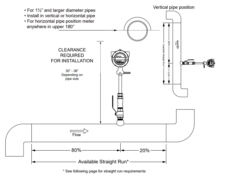
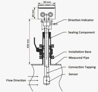
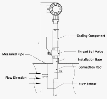
Insertion Magnetic Flow Meter Applications
Raw Water
A Municipal Power Plant was required to monitor its usage of raw water from the Intracoastal Waterway. Lines varied in size from 36 inches to 64 inches and were approximately 10 feet underground.
Install an Insertion magnetic flow meter via a “Wet Tap” procedure to measure the intake and return of the raw water lines. The meters were required to operate underwater (IP 68) due to flooding conditions. The electronics converter was installed in a control room 300 feet away from the sensors.
Food Industry
The sensor of the electromagnetic flowmeter is easily disassembled, which is convenient for cleaning and is convenient for steam sterilization on a regular basis. Therefore, in the health industry, electromagnetic flowmeters must comply with hygienic specifications.
Our product is widely used in these industries:
- Potable Water
- Water Distribution
- Pumping Stations
- Filter Balancing and Backwash
- Reclaimed Water
- Treated Water
- Irrigation Water
- Cooling Water
- Raw Water
Insertion Magnetic Flow Meter Working Principle
The insertion magnetic flowmeter is based on Faraday’s law.When measuring flow, a liquid flows through a magnetic field perpendicular to the direction of flow and induces a voltage proportional to the average flow rate (volume flow). Its induced voltage signal is detected through two electrodes that are in direct contact with the liquid. Voltage signal will be transmitted to the smart transmitter through a dedicated cable. The smart transmitter performs calculations based on the magnitude of the electric potential and the mathematical model of the electromagnetic flow. And converts it into a flow signal for on-site display. Including instantaneous and cumulative quantities can be display. Then output the standard 4 ~ 20MA and 1 ~ 5VDC signals to the flow secondary meter or DCS.
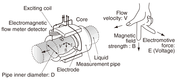
Faraday’s Formula
E is proportional to V x B x D where:
E = The voltage generated in a conductor
V = The velocity of the conductor
B = The magnetic field strength
D = The length of the conductor
Best Technology Guide to Magnetic Flow Meters
Q&A
Techincal Support
Insertion Magnetic Flow Meter Manufacturer
Sino-Inst is a Professional flowmeter manufacturer from China. Sino-Inst offers over 100 flow meter products. About 30% of these are magnetic flow meters, and others are turbine, vortex, ultrasonic, and mass flow meters. A wide variety of flow meter options are available to you, such as free samples, paid samples.
In order of usage, water/wastewater industry, chemical. Food and beverage, oil and gas (although not for oil and gas fluids but in support of the processes). Power, pulp and paper, metals and mining, and pharmaceutical.
If you need to purchase an insertion electromagnetic flowmeter or have other flow measurement needs, please feel free to contact us.
-1.jpg)


