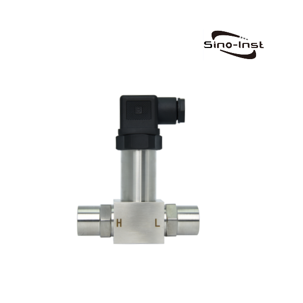

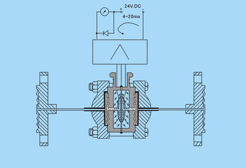
The output signal of the differential pressure transmitter can be a voltage signal or a current signal.
Normally, its output signal is a standard signal, such as 4~20mA, 1~5V, 0~20mA, 0~5V, RS485, etc. The intelligent type can be configured with 4~20mA+Hart protocol. These signals can be controlled, adjusted and monitored by PLC, DCS and other equipment.
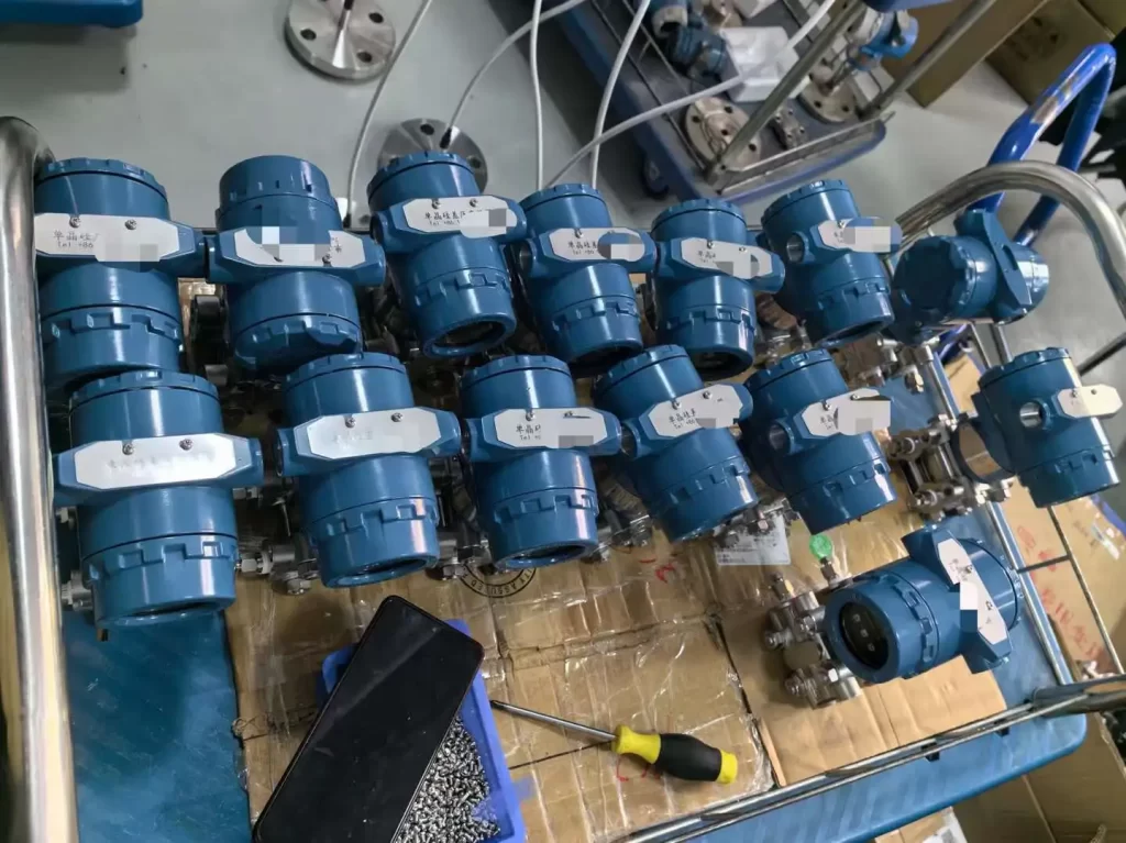
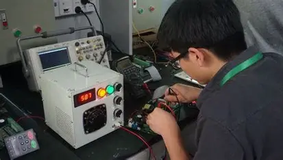
Calibration of conventional differential pressure transmitters:
First adjust the damping to zero state, first adjust the zero point. Then add the full pressure and adjust the full range so that the output is 20mA.
On-site adjustment is all about fast. Here we introduce the quick adjustment method of zero point and range.
When adjusting the zero point, it has almost no impact on the full scale. However, when adjusting the full scale, it has an impact on the zero point. Without migration, its impact is about 1/5 of the range adjustment amount, that is, the range is adjusted upward by 1mA. The zero point will move upward by about 0.2mA. ,vice versa.
For example: if the input full-scale pressure is 100Kpa, the reading is 19.900mA.
Adjust the range potentiometer so that the output is 19.900+(20.000-19.900)×1.25=20.025mA.
When the range increases by 0.125mA, the zero point increases by 1/5×0.125=0.025.
Adjust the zero point potentiometer so that the output is 20.000mA.
After the zero point and full scale adjustment are normal, check the middle scales to see if they are out of tolerance. Make fine adjustments if necessary. Then adjust migration, linearity, and damping.
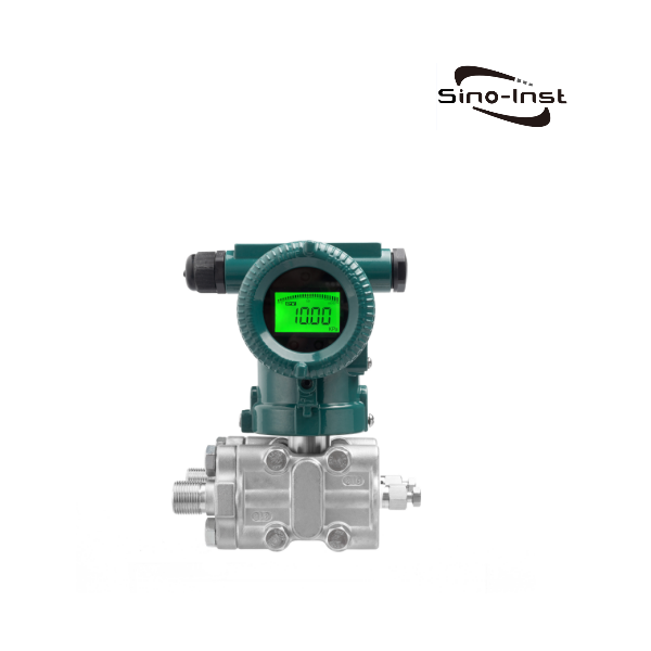
Calibration of intelligent differential pressure transmitter
It is not possible to calibrate the smart transmitter using the above conventional method, because this is determined by the structural principle of the HART transmitter.
Because the intelligent transmitter is between the input pressure source and the generated 4-20mA current signal. In addition to machinery and circuits, there is also a microprocessor chip that operates on the input data, so the adjustment is different from the conventional method.
In fact, manufacturers also have instructions for the calibration of smart transmitters. For example, for ABB transmitters, calibration can be divided into: “setting the range”, “re-ranging” and “fine-tuning”.
The “setting range” operation mainly completes the configuration work through the digital setting of LRV and URV. The “re-ranging” operation requires connecting the transmitter to a standard pressure source. Guided by a series of instructions, the variable The transmitter directly senses the actual pressure and sets the value.
The initial and final settings of the measuring range depend directly on the actual pressure input value. But it should be noted that although the analog output of the transmitter has the correct relationship with the input value used, the digital reading of the process value will show a slightly different value, which can be calibrated through the fine-tuning item.
Since each part needs to be adjusted individually or jointly, the actual calibration can be carried out according to the following steps:
- First make a 4-20mA fine adjustment to calibrate the D/A converter inside the transmitter. Since it does not involve sensing components, no external pressure signal source is required.
- Make full fine-tuning again to make the 4-20mA and digital reading consistent with the actual applied pressure signal. Therefore, a pressure signal source is required.
- Finally do the re-ranging. Adjust the analog output 4-20mA to match the external pressure signal source. Its function is exactly the same as the zero adjustment (Z) and range adjustment (R) switches on the transmitter shell.
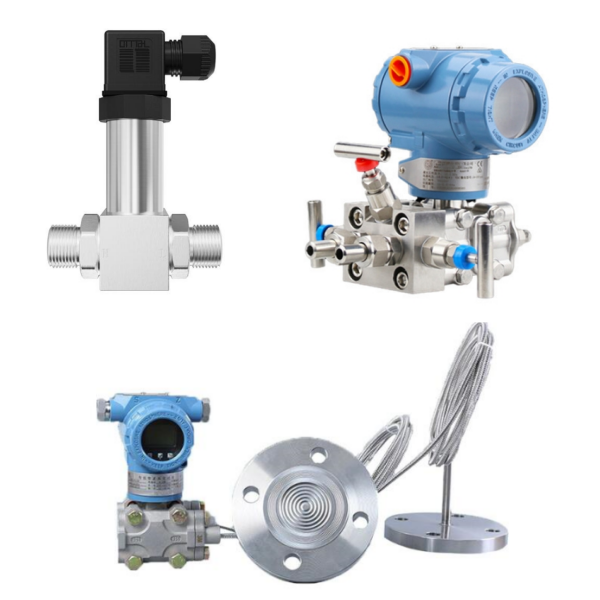
- The installation position of the differential pressure transmitter on the process pipeline is related to the medium being measured. In order to obtain better installation results, the following conditions should be considered:
- ① Prevent the differential pressure transmitter from direct contact with corrosive or overheated measured media;
- ②Prevent debris from depositing and clogging in the pressure pipe;
- ③The length of the pressure pipes on both sides of the positive and negative pressure transmitter should be as consistent as possible;
- ④The liquid column pressure heads in the pressure pipes on both sides of the positive and negative pressure transmitters should be balanced;
- ⑤The pressure pipe should be installed where the temperature gradient and temperature fluctuation are minimal.
- When measuring liquid flow, the differential pressure transmitter should be installed next to or below the pipe being measured so that bubbles can be discharged into the pipe;
- When measuring gas flow, the differential pressure transmitter should be installed next to or above the pipe being measured so that the accumulated liquid can easily flow into the pipe;
- When measuring steam flow, the differential pressure transmitter should be installed below the pipe to be measured so that the condensed water can fill the pressure pipe.
Special attention should be paid to preventing the temperature of the differential pressure transmitter from contacting the medium exceeding the limit temperature of the transmitter when measuring steam or other high-temperature media.