2 Wire-3 Wire-4 Wire Pressure Transducer Wiring Diagrams
There are generally three types of Pressure transducer wiring diagrams: two-wire, three-wire, and four-wire. As the name suggests, there are several wires that need to be connected to the electrical interface of the pressure transmitter, which is a multi-wire connection method.
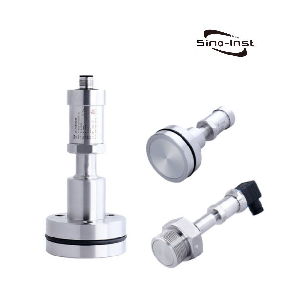
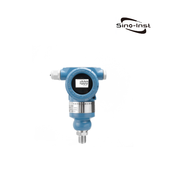
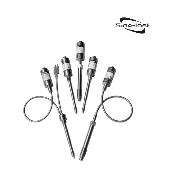
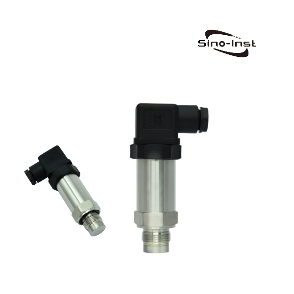
When purchasing the signal output of the pressure transmitter, you also need to choose the wire system. For example, the commonly used 2-wire 4-20mA signal output. Sino-Inst supplies a variety of 2-wire-3-wire-4 wire pressure transducers.
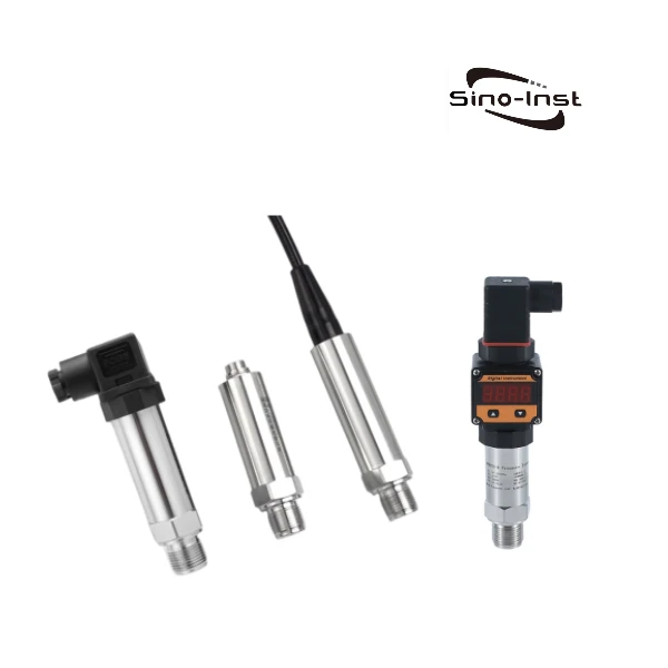
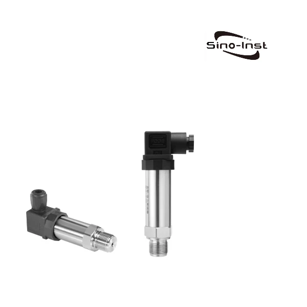
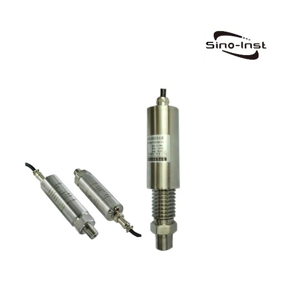
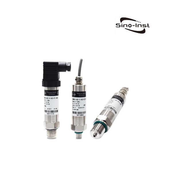
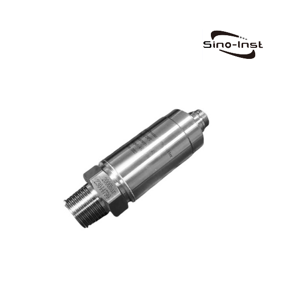
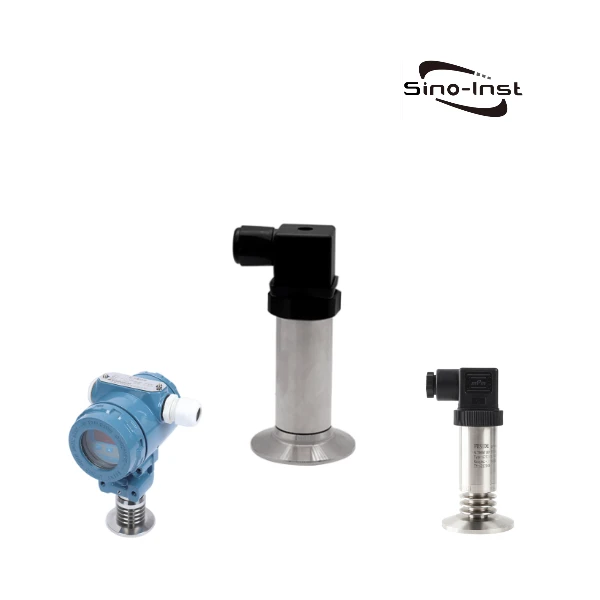
Featured Industrial Pressure Transducers
2 Wire-3 Wire-4 Wire Pressure Transducer Wiring Diagram
The name wire system came about after the birth of the two-wire system transmitter. This is the result of the widespread use of electronic amplifiers in instruments. The essence of amplification is an energy conversion process, which cannot be separated from power supply.
Therefore, the four-wire transmitter appeared first; that is, two wires are responsible for the power supply, and the other two wires are responsible for outputting the converted and amplified signals (such as voltage, current, etc.). But at present, many transmitters adopt two-wire system. Next, let’s take a closer look at the differences between different wire transmitters?
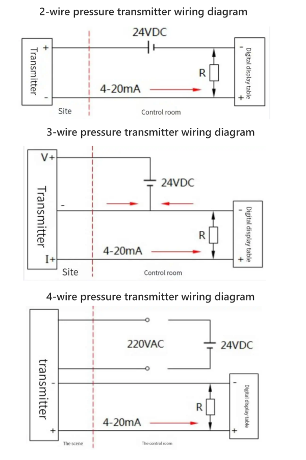
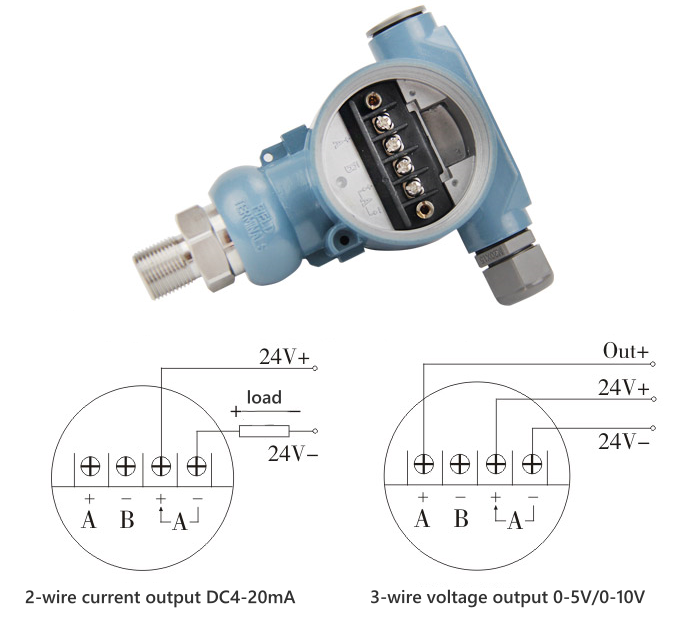
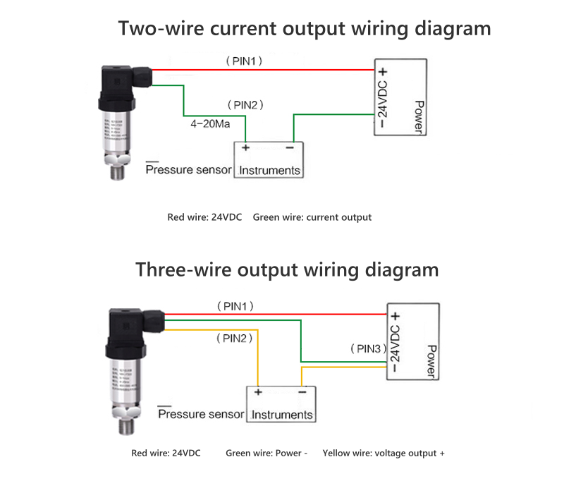
2-wire Pressure Transducer Wiring Diagram
The two-wire pressure transmitter wiring method is currently the most common wiring method.
Two wires form a loop, which is both a loop that provides power support for the pressure transmitter and a loop that transmits current signals. That is to say, in two-wire wiring, the output load and power supply of the pressure transmitter are connected in series.
This connection method is usually used by pressure transmitters that output current signals, such as standard electronic control signals of 4~20mA.
When the two-wire system needs to output a voltage value, it can be measured by connecting a resistor in series, such as a 250Ω resistor in series with a 4-20mA current circuit.
3-wire Pressure Transducer Wiring Diagram
The wiring method of the three-wire pressure transmitter is to separate the positive terminal of the power supply and the positive terminal of the signal output, but their other terminals are connected with the same wire.
In this case, the actual path of the current is still a loop composed of the positive and negative poles of the power supply. The current at the positive terminal of the signal is close to 0 and can only transmit the potential voltage. It can be understood as the voltage range of the multimeter, and the load is approximately infinite. Break circuit.
All pressure transmitters that use this connection method output voltage signals such as 1~10V, 1~5V, 0~5V and other standard control signals.
4-wire Pressure Transducer Wiring Diagram
The four-wire system is different from the two-wire system and the three-wire system. It consists of two independent circuits that do not interfere with each other. Because the output circuit is independent, it can output either a voltage signal or a current signal.
More Pressure Measurement Solutions
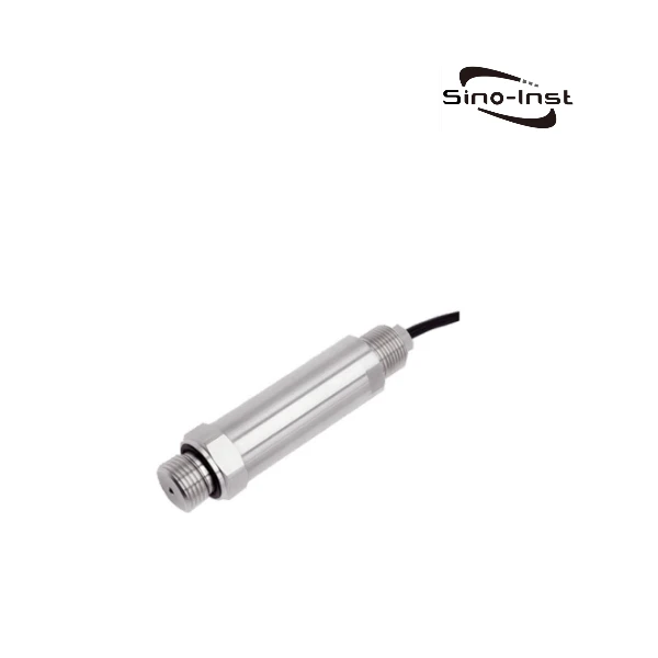
- Industrial Analog Pressure Transducers | 4-20mA, 0-5/10V DC
- Submersible Pressure Transducers for Liquid Pressure and Level Measurement
- Explosion Proof Pressure Transducers- Intrinsically Safe – ExdIICT6-ExiaIICT6 Ga
- Voltage Output Pressure Transducers | 0-5/10V DC, 1~5VDC, 0.5~2.5VDC
- Pressure Transducer Troubleshooting: Expert Insights & Tips
- Fluid Pressure Guide: Static Pressure Vs. Dynamic Pressure Vs. Total Pressure
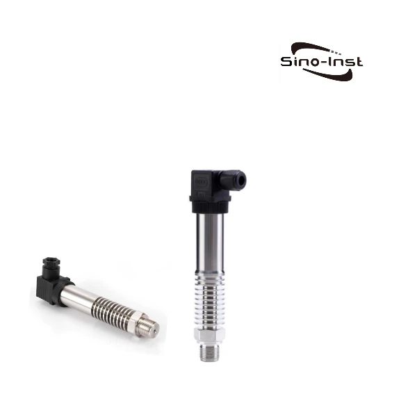
- Industrial Hydrogen Pressure Transmitters/Transducers
Sino-Inst produces and supplies a variety of pressure transmitters, including two-wire, three-wire, and four-wire wiring forms. When selecting a model, users should pay attention to the unification of the signal system, explosion-proof requirements, requirements for receiving equipment, cost and other issues to comprehensively consider the choice.
If you need to purchase an industrial pressure transmitter, or have questions about the pressure transmitter wiring and signal output, you can contact our engineers at any time!

Zhang Wei, possesses 20 years of experience as an automation instrumentation engineer, specializing in the research, design, installation, commissioning, and maintenance of automation instruments.
Face to various instrument communication protocols (such as Modbus, Profibus, etc.), with solid hardware circuit design and software programming skills (proficient in C language and PLC programming). Has extensive project experience; projects he has led and participated in have all achieved outstanding results, improving product accuracy, reducing costs, and increasing production efficiency.
Possesses excellent communication and coordination skills and a strong team spirit, enabling him to quickly respond to customer needs and provide high-quality automation instrumentation solutions.