Home > Blog > 7-Point Checklist for Selecting Industrial Oxygen Flow Meters
7-Point Checklist for Selecting Industrial Oxygen Flow Meters
The accurate flow measurement of oxygen is a foundational requirement across numerous industrial, medical, and scientific domains.
Here, we’ll explore the principles and practices of selecting the right Industrial Oxygen Flow Meters. We’ll analyze gaseous and liquid oxygen, as well as factors like temperature and pressure, and compare various flow measurement technologies. Our goal is to provide a structured framework to help you make an informed purchasing decision.
The task of measuring the flow of oxygen presents a unique set of challenges that distinguish it from the measurement of more inert fluids. Oxygen is not merely a gas; it is a powerful oxidizer, a life-sustaining element, and a critical industrial reagent. Its behavior changes dramatically from a gas at ambient temperature to a cryogenic liquid at -183°C (-297°F). Consequently, selecting an oxygen flow meter is not a simple matter of matching pipe size and flow rate. It is an exercise in careful consideration, demanding a deep understanding of the fluid’s properties, the process’s demands, and the inherent safety risks.
Imagine trying to measure the flow of water. You have many options, and for the most part, the primary risk of a poor choice is inaccuracy. Now, imagine that water has the ability to cause many common materials to spontaneously burst into flames. The stakes are immediately raised. This is the reality of handling pure oxygen. A seemingly minor oversight, such as choosing a meter with incompatible lubrication or a material that is not oxygen-rated, can have catastrophic consequences. Our guide is structured as a deliberative checklist, designed to walk you through the essential considerations for selecting a reliable, safe, and cost-effective industrial oxygen flow meter.
Point 1: Characterize Your Oxygen and Flow Conditions
Before we can even begin to speak of technologies or models, we must first develop a complete portrait of the fluid we intend to measure. Oxygen’s identity is not fixed; it shifts with temperature and pressure. Understanding its state within your specific process is the foundational first step.
Gaseous Oxygen vs. Liquid Oxygen (LOx)
The most fundamental distinction to make is whether you are measuring oxygen in its gaseous or liquid state. These two phases present vastly different challenges.
Gaseous Oxygen (O2):
In its gaseous form, oxygen is typically measured in applications like medical gas distribution in hospitals, combustion air control in furnaces, or as a reactant in chemical processes. The primary variables here are pressure and temperature. Because gases are compressible, a change in either pressure or temperature will directly affect the gas’s density, and therefore the mass of oxygen flowing through the pipe. A simple volumetric flow meter (which measures volume, like liters per minute) might give a misleading reading if pressure or temperature fluctuates. For this reason, many O2 flow meter applications for gas require mass flow measurement, which provides a reading independent of these changes.
Liquid Oxygen (LOx):
Liquid oxygen is a cryogenic fluid, existing at extremely low temperatures (below -183°C or -297°F). Handling LOx introduces the complexities of cryogenics. The materials of the flow meter must be able to withstand these frigid temperatures without becoming brittle or failing. Furthermore, any heat leak from the flow meter into the LOx can cause it to boil, creating a two-phase flow (a mix of liquid and gas bubbles). This two-phase condition can render many flow meter technologies inaccurate or inoperable. Therefore, a liquid oxygen flow meter must not only be materially compatible with cryogenic temperatures but also be designed to minimize heat transfer and handle the potential for phase changes.
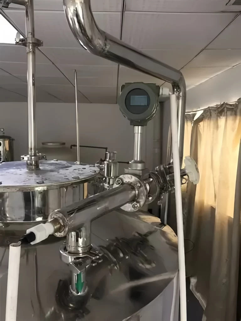
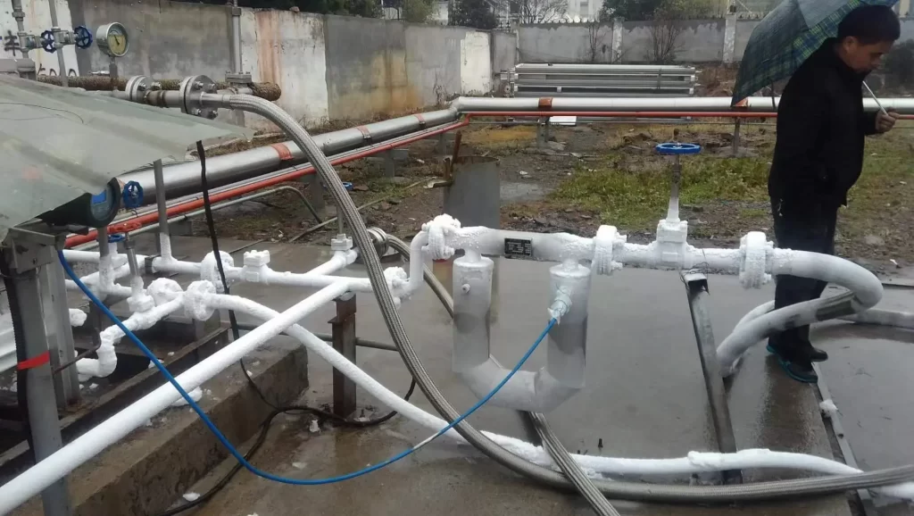
Coriolis mass flow meter measures cryogenic liquid nitrogen
Operating Pressure and Temperature Range
Once you have identified the phase of the oxygen, you must quantify the exact conditions of your process. You need to know not just the “normal” operating pressure and temperature, but the full range.
Maximum Pressure: What is the highest pressure the meter will ever be exposed to, even during a system startup or potential fault condition? The meter’s body must be rated to safely contain this pressure.
Minimum Pressure: What is the lowest operating pressure? This affects gas density calculations.
Normal Operating Temperature: This is the temperature during typical, steady-state operation.
Maximum and Minimum Temperature: Consider ambient temperature swings, process upsets, or the cool-down phase for cryogenic systems.
Flow Rate and Turndown Ratio
Finally, you must define the flow rate itself. This is more nuanced than a single number.
Maximum Flow Rate: The highest flow you need to measure accurately.
Minimum Flow Rate: The lowest flow you need to measure accurately.
Normal Flow Rate: The most common flow rate during operation.
From these values, we derive a critical parameter: the turndown ratio. The turndown ratio is simply the ratio of the maximum flow rate to the minimum flow rate that a meter can accurately measure. For example, if a meter can measure accurately from 100 liters per minute down to 10 liters per minute, it has a turndown ratio of 10:1.
Why does this matter? Some processes have very steady flow rates, while others vary widely. A hospital’s oxygen demand, for instance, can be low overnight but spike during the day. An industrial batch process might require a high flow for a short period and then no flow at all. You must select a meter with a turndown ratio that accommodates your process’s full dynamic range. Choosing a meter with an inadequate turndown ratio is like having a car speedometer that is only accurate between 50 and 60 mph—useless for driving in the city.
Point 2: Define Your Accuracy and Repeatability Requirements
The terms “accuracy” and “repeatability” are often used interchangeably in casual conversation, but in process measurement, they have distinct and important meanings. Understanding this distinction is vital for selecting a meter that meets your needs without being excessively expensive.
Accuracy vs. Repeatability: What’s the Difference?
Let’s use an analogy. Imagine you are an archer shooting arrows at a target.
Accuracy refers to how close your arrows are to the bullseye. An accurate archer consistently hits the center of the target. In flow measurement, accuracy is how close the meter’s reading is to the true, actual flow rate. It is often expressed as a percentage of the reading or a percentage of the full-scale range.
Repeatability refers to how close your arrows are to each other, regardless of where they are on the target. A repeatable archer might have a tight cluster of arrows in the top-left corner. They are not accurate (not hitting the bullseye), but they are very consistent. In flow measurement, repeatability is the meter’s ability to produce the same reading every time the exact same flow rate passes through it.
For some processes, repeatability is more important than absolute accuracy. In a batch-making process, for example, you might need to add the exact same amount of oxygen every time to ensure product consistency. As long as the meter is repeatable, you can achieve this, even if the absolute reading is off by a small amount. For custody transfer applications, where oxygen is being bought or sold, absolute accuracy is paramount because money is changing hands based on the measured amount.
Understanding Accuracy Specifications
Flow meter accuracy is typically specified in one of two ways:
Percentage of Reading (% RD): This means the error is a percentage of the actual flow rate. For example, a meter with ±1% of reading accuracy will have an error of ±0.5 Standard Cubic Feet per Minute (SCFM) at a flow rate of 50 SCFM, and an error of ±1 SCFM at a flow rate of 100 SCFM. This is generally preferred because the accuracy is maintained across the flow range.
Percentage of Full Scale (% FS): This means the error is a constant value based on the meter’s maximum flow capacity. For a 200 SCFM meter with ±1% of full-scale accuracy, the potential error is ±2 SCFM, whether you are measuring 200 SCFM or 20 SCFM. This means the relative error becomes very large at lower flow rates. At 20 SCFM, a ±2 SCFM error is a massive ±10% error!
It is vital to read the datasheet carefully. A meter that boasts “1% accuracy” might be 1% of full scale, which could be insufficient for your application if you operate at the low end of its range.
The Role of Calibration
No flow meter is perfect out of the box. Calibration is the process of comparing a meter’s readings to a known standard of higher accuracy (a calibration standard traceable to an institution like the National Institute of Standards and Technology, NIST) and adjusting the meter to minimize its error.
For oxygen service, calibration must be performed using a gas that safely simulates oxygen’s properties, or in some cases, with oxygen itself under highly controlled, safe conditions. You must consider:
Does the manufacturer provide a traceable calibration certificate?
What is the recommended recalibration interval?
What are the costs and logistics associated with recalibration? Will the meter need to be sent back to the factory, or can it be calibrated in the field?
For critical applications, the investment in a highly accurate and stable meter that requires less frequent calibration can lead to significant long-term savings and greater process reliability.
Point 3: Compare Oxygen Flow Meter Technologies
With a clear understanding of your process conditions and accuracy needs, we can now explore the different types of flow meters available for oxygen service. Each technology operates on a different physical principle and has its own set of strengths and weaknesses. There is no single “best” type; the best choice is always context-dependent.
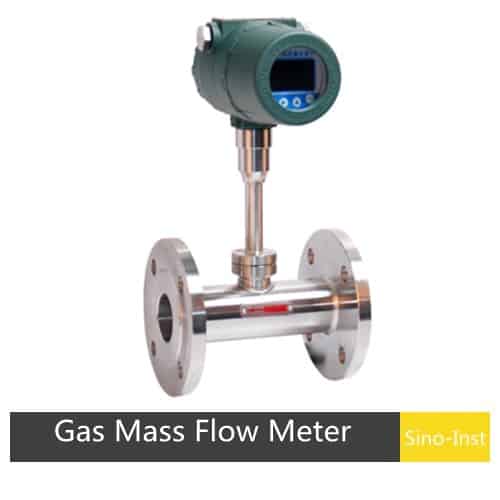
Thermal mass flow meters are one of the most common choices for gaseous O2 flow meter applications.
How They Work: They operate by introducing a known amount of heat into the flowing gas stream and measuring the cooling effect. Two temperature sensors are used: one is a reference, and the other is heated to a constant temperature difference above the reference. As gas flows past the heated sensor, it carries away heat, and the sensor cools down. The amount of power required to maintain the constant temperature difference is directly proportional to the mass flow rate of the gas.
Why They Are Suited for Oxygen: Because they directly measure mass flow, their readings are not affected by changes in gas pressure or temperature. This eliminates the need for separate pressure and temperature transmitters and a flow computer to calculate compensated flow, simplifying the installation and reducing costs. They have excellent turndown ratios (often 100:1 or better) and are very sensitive to low flow rates.
Considerations: Most thermal mass meters are insertion-style or inline. They have sensors that are wetted by the process gas, so material compatibility and cleanliness are paramount. They must be calibrated for the specific gas composition. While they are excellent for clean, dry gas, they can be affected by moisture or particulate matter in the gas stream.
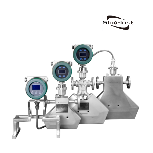
Coriolis Mass Flow Meters
Coriolis meters are the “gold standard” for accuracy and are capable of measuring both gas and liquid oxygen.
How They Work: The meter works by vibrating one or more tubes through which the fluid flows. The flowing fluid induces a twisting motion in the tubes due to the Coriolis effect (the same effect that influences weather patterns on Earth). Sensors placed on the tubes measure the degree of this twist, which is directly proportional to the mass flow rate. Simultaneously, the vibrational frequency of the tubes can be measured, which is directly related to the fluid’s density.
Why They Are Suited for Oxygen: They offer exceptionally high accuracy (often ±0.1% of reading or better). They directly measure mass flow and density, making them ideal for custody transfer or critical process control. Since they can measure density, they can also be used to infer the quality of the oxygen. They have no moving parts in the traditional sense and an unobstructed flow path, which minimizes pressure drop. They are suitable for both high-pressure gas and cryogenic liquid oxygen flow meter applications.
Considerations: Coriolis meters are typically the most expensive option. They can be heavy and may require significant support for the piping. They are also sensitive to vibrations from external sources, although modern designs have sophisticated methods to filter this out.
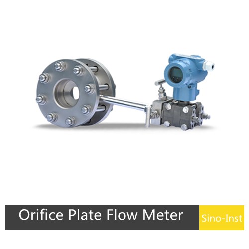
Differential Pressure (DP) Flow Meters
DP flow meters are one of the oldest and most widely understood flow measurement technologies.
How They Work: They operate by placing a precisely engineered restriction, such as an orifice plate, venturi tube, or averaging pitot tube, into the flow stream. This restriction creates a pressure drop. The higher the flow rate, the greater the pressure drop. By measuring the pressure upstream and downstream of the restriction with a differential pressure transmitter, the volumetric flow rate can be calculated.
Why They Are Suited for Oxygen: The technology is mature, well-documented, and relatively inexpensive to implement, especially for larger line sizes. There are established standards for their use in oxygen service.
Considerations: DP meters measure volumetric flow, not mass flow. To get an accurate mass flow reading for gaseous oxygen, you must also measure the pressure and temperature and use a flow computer to perform a density compensation calculation. They have a limited turndown ratio, typically only 4:1. The orifice plate can wear over time, affecting accuracy, and the sharp edges can be an ignition concern if not properly manufactured and maintained for oxygen use. They also introduce a permanent pressure loss into the system, which equates to wasted energy.
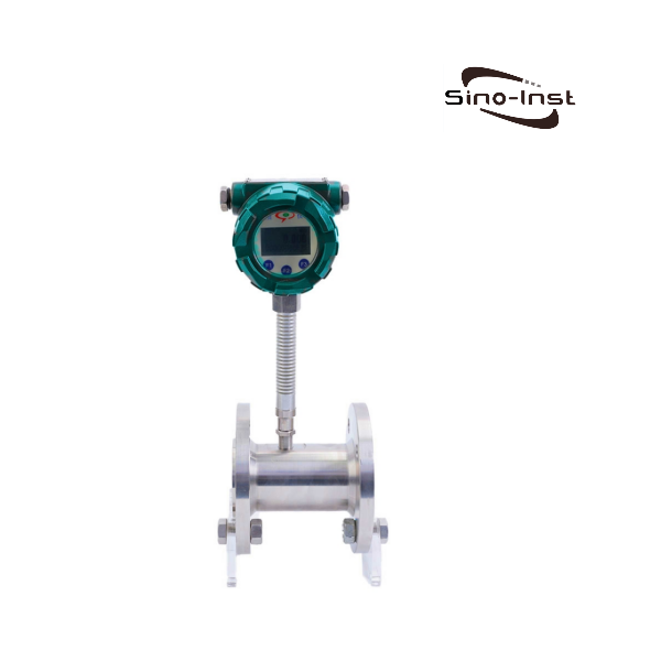
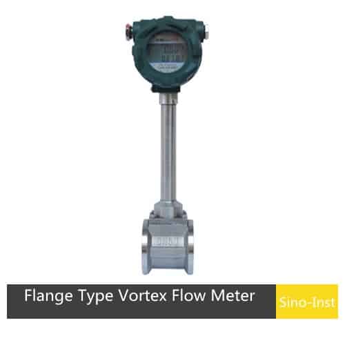
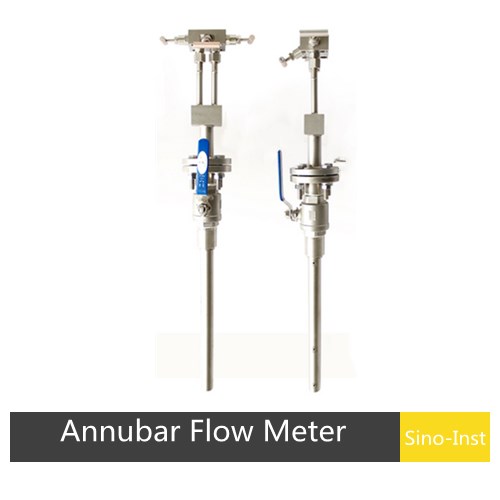
Vortex Flow Meters
Vortex meters offer a good balance of performance and cost for many applications.
How They Work: A “bluff body” or “shedder bar” is placed in the flow path. As the fluid flows past this body, it creates alternating vortices, similar to the way a flag flutters in the wind. The frequency at which these vortices are shed is directly proportional to the fluid velocity. A sensor detects these vortices and converts the frequency into a flow rate.
Why They Are Suited for Oxygen: They are robust, have no moving parts, and are not significantly affected by changes in fluid density (for velocity measurement), pressure, or temperature. They offer good accuracy and a better turndown ratio than DP meters. They can be used for both gaseous and liquid oxygen, provided the materials are appropriate.
Considerations: Like DP meters, they primarily measure velocity (and thus volumetric flow), so mass flow calculation requires separate pressure and temperature inputs. They require a well-developed flow profile, meaning they need a significant length of straight, unobstructed pipe upstream and downstream to be accurate. They also have a minimum flow threshold below which they stop detecting vortices and the reading drops to zero.
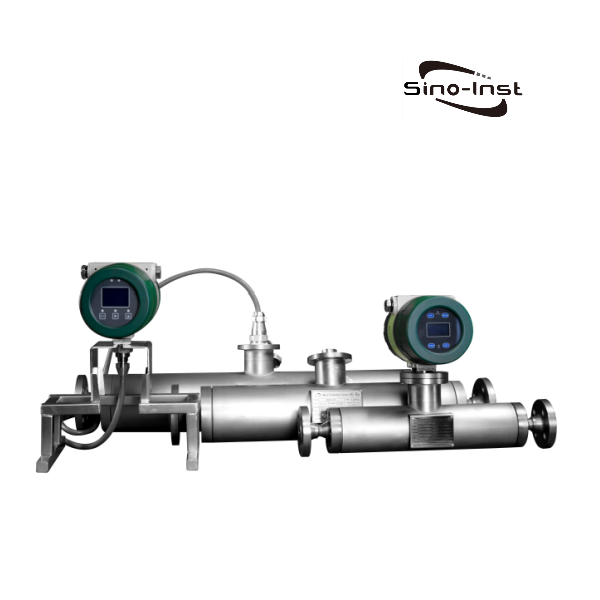
Cryogenic Turbine Flowmeter
The cryogenic turbine flowmeter is a high-precision, low-temperature flowmeter capable of measuring temperatures down to -196°C. It is suitable for cryogenic liquids such as liquefied natural gas (LNG), liquid nitrogen, liquid oxygen, liquid chlorine, liquid CO2, liquid argon, and liquid ammonia. It can also measure the volume of liquids such as diesel, gasoline, and low-viscosity crude oil.
This turbine flowmeter is a new type of intelligent instrument developed using ultra-low-power single-chip microcomputer technology, integrating a turbine flow sensor with a display and totalizer. Its dual-row LCD display offers significant advantages, including compact design, intuitive and clear readings, high reliability, immunity to external power supply interference, lightning resistance, and low cost.
It features three-point meter coefficient correction, intelligent compensation for meter coefficient nonlinearity, and field correction. All Sino-Inst liquid turbine flowmeters are explosion-proof, with an explosion-proof rating of ExdIIBT6.
The choice among these technologies hinges on a careful balancing of your priorities. Is supreme accuracy your goal, suggesting a Coriolis meter? Is it measuring dry, gaseous oxygen over a wide range on a budget, pointing towards a thermal gas flowmeter? Or is it a high-flow, general-purpose application where a Vortex meter provides a sweet spot of reliability and cost?
Point 4: Prioritize Material Compatibility and Safety
When dealing with oxygen, safety is not merely a consideration; it is the paramount concern that must govern every decision. Oxygen itself does not burn, but it is a powerful oxidizer. This means it readily supports the combustion of other materials. In an oxygen-enriched environment (typically defined as having more than 23.5% oxygen), materials that are non-flammable in normal air can burn vigorously. The risk of fire is the single most important hazard to manage.
The Fire Triangle in Oxygen Systems
A fire requires three components: fuel, an oxidizer, and an ignition source. In an oxygen system, you have an abundance of the oxidizer. The “fuel” can be the materials of the flow meter itself, any contaminants like oil or grease, or even tiny particles in the gas stream. The challenge, therefore, is to eliminate the ignition source.
Ignition sources in an oxygen system can include:
Adiabatic Compression: When a gas is compressed rapidly, its temperature rises. If a high-pressure oxygen valve is opened suddenly into a downstream section of pipe, the gas in that section can be compressed so quickly that its temperature spikes, potentially igniting any contaminants or susceptible materials.
Particle Impact: A small metallic particle traveling at high velocity in the gas stream can strike a surface (like the inside of a flow meter or a valve seat) and create a spark, igniting the particle or the surrounding material.
Friction: The rubbing of two incompatible materials can generate enough heat to cause ignition.
Static Discharge: The flow of dry gas can generate static electricity, which could discharge and provide an ignition spark.
Selecting Oxygen-Clean and Compatible Materials
The primary strategy for preventing ignition is to select materials that are resistant to ignition in high-pressure oxygen and to ensure the entire system is meticulously cleaned.
Material Selection: Not all metals are equal when it comes to oxygen service. The choice of material depends on the pressure, temperature, and velocity of the oxygen. Common acceptable materials include:
Elastomers and Plastics (Seals, Gaskets): Any non-metallic components must be specifically approved for oxygen service. Materials like Viton (FKM) or Teflon (PTFE) that have been specially formulated and tested for oxygen compatibility are often used. Standard Buna-N or Neoprene seals are generally unacceptable.
Monel and other Nickel-Copper Alloys: These are highly resistant to ignition and are often required for high-pressure (>750 psi) oxygen systems.
Brass and Bronze: These copper alloys have a long history of safe use in oxygen systems at lower and medium pressures. They are less prone to ignition from particle impact than stainless steel.
Stainless Steel (e.g., 304, 316): While widely used, stainless steel is more susceptible to ignition than brass or Monel, especially from particle impact. Its use is often limited to lower pressure and velocity applications, and its selection requires careful evaluation.
The following table provides a simplified overview of material considerations. Always consult detailed standards like CGA G-4.4 for definitive guidance.
Material
Pressure Suitability
Ignition Resistance
Notes
Monel / Ni-Cu Alloys
High
Excellent
Preferred for critical, high-pressure applications.
Brass / Bronze
Low to Medium
Good
Excellent choice for valves and fittings at moderate pressures.
Stainless Steel
Low to Medium
Fair
Use requires careful analysis of pressure, temperature, and velocity.
Aluminum
Low
Poor
Generally avoided for primary containment in pressure systems.
Standard Polymers
N/A
Very Poor
Unacceptable; can be a fuel source. Use only oxygen-rated polymers.
The Criticality of “Oxygen Cleaning”
Even if the correct materials are chosen, the system is only safe if it is perfectly clean. The term “oxygen clean” refers to a specific cleaning process designed to remove all incompatible contaminants, especially hydrocarbons like oils, greases, and fibers. A residue of oil from a technician’s fingerprint can be sufficient fuel for a fire in a high-pressure oxygen system.
An oxygen cleaning procedure, such as the one outlined in the Compressed Gas Association’s standard CGA G-4.1, typically involves:
Degreasing: Using an approved, oxygen-compatible solvent to remove all hydrocarbon residues.
Rinsing: Thoroughly rinsing the component to remove the solvent.
Drying: Drying the component with clean, dry, oil-free nitrogen or air.
Inspection: Inspecting the component under ultraviolet (UV) light (a “black light”) to ensure no fluorescent hydrocarbon residues remain.
Bagging and Sealing: Immediately sealing the clean component in a durable, clean plastic bag to prevent re-contamination before installation.
When you purchase an oxygen flow meter, you must specify that it needs to be “cleaned for oxygen service.” The manufacturer will perform this procedure and provide the meter in a sealed bag with certification. This is not an optional add-on; it is a fundamental safety requirement.
Point 5: Plan for Installation and Environmental Realities
A perfectly specified flow meter can still provide poor data if it is installed incorrectly. The physical installation and the surrounding environment play a significant role in the performance and longevity of any piece of industrial process instrumentation. For oxygen meters, these considerations are intertwined with safety.
Straight Pipe Run Requirements
Many flow meter technologies, particularly vortex and differential pressure types, are sensitive to the “flow profile.” They need the fluid to be flowing smoothly and without swirl to provide an accurate reading. The primary source of flow profile distortion is upstream piping elements like elbows, valves, and reducers.
To ensure a smooth, fully developed flow profile, manufacturers specify a minimum length of straight, unobstructed pipe that must be installed immediately before and after the meter. This is typically expressed in multiples of the pipe diameter (D). For example, a vortex meter might require 15D of straight pipe upstream and 5D downstream. For a 4-inch pipe, this would mean 60 inches (5 feet) of straight pipe before the meter and 20 inches after.
Why it matters: Failing to provide the required straight run can introduce errors of 5%, 10%, or even more. It is one of the most common sources of poor flow meter performance.
What to do: Before selecting a meter, survey your intended installation location. Do you have enough straight pipe available? If space is tight, you might need to consider a technology that is less sensitive to flow profile, such as a Coriolis meter, or install a flow conditioning plate, which can reduce the straight run requirement but adds cost and a pressure drop.
The correct physical orientation of the meter is also important.
Gas Flow: For gaseous oxygen, the orientation is often flexible, but mounting the meter in a horizontal pipe run is common. It is important to ensure that any condensation or moisture in the line cannot collect in the meter’s sensing elements.
Liquid Flow: For a liquid oxygen flow meter, installation is more critical. The meter should be installed in a way that keeps it completely full of liquid. Mounting it in a vertical pipe with the flow going upwards is often the best practice. This helps to sweep any gas bubbles (from boiling) through the meter rather than allowing them to collect at a high point, which would cause significant measurement errors.
Vibration: All flow meters can be affected by excessive pipe vibration. Coriolis meters are particularly sensitive, although modern transmitters have advanced digital signal processing to filter out noise. Ensure the piping is well-supported and consider the proximity of pumps, compressors, or other vibration sources.
Environmental Protection
The industrial environment can be harsh. You must consider the external factors that the flow meter will be exposed to.
Ingress Protection (IP) Rating: This rating defines how well the meter’s housing is sealed against the intrusion of dust and water. A rating like IP66 means the unit is dust-tight and protected against powerful water jets. This is important for outdoor installations or areas subject to washdowns.
Hazardous Area Certifications: If the meter is being installed in an area where flammable gases or dusts may be present (a “hazardous area”), it must have the appropriate safety certification, such as ATEX (in Europe) or IECEx/UL (in North America). These certifications ensure the meter’s electronics are housed in a way (e.g., explosion-proof or intrinsically safe) that prevents them from becoming an ignition source for the surrounding atmosphere. While oxygen itself is not flammable, it is often used in processes involving flammable hydrocarbons, making this a common requirement.
Ambient Temperature: The meter’s electronic components have an operating temperature range. An installation in direct sunlight in a hot climate or outdoors in a cold climate must be within the meter’s specified limits. Sunshades or instrument heating may be necessary.
Point 6: Specify Communication Outputs and System Integration
In a modern industrial plant, a flow meter is rarely a standalone device with a simple local display. It is a data-gathering instrument that must communicate its measurements to a larger control system, such as a Programmable Logic Controller (PLC) or a Distributed Control System (DCS). The way the meter communicates is a key part of its specification.
Analog vs. Digital Communication
4-20 mA Analog Output: This has been the industry standard for decades. The flow meter outputs a current signal that varies from 4 milliamps (representing 0% flow) to 20 milliamps (representing 100% flow). This is a simple, robust, and well-understood signal. The “live zero” (4 mA) is a key feature; if the signal drops to 0 mA, it indicates a fault, like a cut wire, which is more useful than a 0-volt signal that could mean either zero flow or a dead instrument.
Pulse/Frequency Output: Some meters, like vortex or turbine meters, naturally produce a pulse output where each pulse represents a discrete volume of fluid. This can be sent to a flow computer or a counter.
Digital Communication Protocols: While 4-20 mA is reliable, it can only transmit one piece of information (the process variable, i.e., the flow rate). Modern “smart” transmitters can measure and report much more. Digital protocols allow the meter to send multiple pieces of information over the same pair of wires.
HART (Highway Addressable Remote Transducer) Protocol: This is a hybrid protocol that superimposes a digital signal on top of the standard 4-20 mA analog signal. This allows the primary flow reading to be read by the legacy analog system, while a maintenance technician with a handheld communicator can access secondary variables (like temperature in a thermal mass meter), diagnostics, and configuration parameters. It offers the best of both worlds: backward compatibility and enhanced functionality.
Fieldbus (e.g., FOUNDATION Fieldbus, Profibus PA): These are fully digital, multi-drop protocols. Multiple instruments can be connected on a single pair of wires, and all information—process variables, diagnostics, configuration—is communicated digitally. This can reduce wiring costs and provide a wealth of data for asset management and predictive maintenance.
Modbus: This is a simpler, open serial protocol that is widely supported. It is common for connecting instruments to PLCs.
Why choose a meter with digital communication? The primary benefit is access to advanced diagnostics. A smart O2 flow meter can tell you more than just the flow rate. It can tell you about its own health.
For example, a Coriolis meter might report that its tube is becoming coated or that it is experiencing excessive external vibration. A thermal mass meter could detect a buildup of dirt on its sensors. This information allows maintenance to be performed proactively, before the measurement becomes inaccurate or the meter fails completely. This shift from reactive to predictive maintenance can significantly reduce downtime and improve overall plant reliability. The choice of communication protocol should align with your plant’s control system architecture and your long-term maintenance strategy.
Point 7: Analyze the Total Cost of Ownership (TCO)
The purchase price of an industrial oxygen flow meter is only one component of its total cost. A cheaper meter might end up costing far more over its lifespan. A thoughtful analysis of the Total Cost of Ownership (TCO) provides a more complete financial picture and often justifies the selection of a higher-quality instrument.
Components of TCO
TCO includes all direct and indirect costs associated with the meter from procurement to decommissioning.
Purchase Price (CAPEX): This is the upfront capital expenditure for the meter and any necessary accessories (flanges, power supplies, etc.).
Installation Costs: This includes the labor to install the meter, any required piping modifications (like adding straight runs), wiring, and commissioning. A meter that is complex to install or requires extensive pipe rework will have a higher installation cost.
Energy Costs: Some flow meters introduce a pressure drop into the process line. Overcoming this pressure drop requires energy from a pump or compressor. While often small for a single meter, this cost can be significant over the life of the instrument, especially in large-scale, continuous processes. Meters with an unobstructed flow path, like Coriolis or full-bore magmeters (not used for oxygen), have the lowest energy costs. DP meters with orifice plates have the highest.
Maintenance and Calibration Costs (OPEX): This is a major component of operating expenditure.
Routine Maintenance: Does the meter have parts that wear, like the bearings in a turbine meter, or impulse lines that can clog on a DP meter?
Calibration: How often does the meter need to be recalibrated? Does it need to be removed from the line and sent to a lab, resulting in process downtime? Or can it be verified in-situ? Coriolis meters, for example, are known for their long-term stability and may not require recalibration for many years.
Downtime Costs: What is the cost to your process if the meter fails or provides an inaccurate reading? In a critical process, an unreliable meter can lead to lost production, off-spec product, or safety incidents, the costs of which can easily dwarf the purchase price of the instrument. A more reliable, albeit more expensive, meter is often a wise investment.
A TCO Thought Experiment
Consider two options for a gaseous oxygen application:
Option A: Differential Pressure Meter. Low purchase price. However, it requires a DP transmitter, a temperature transmitter, a pressure transmitter, and a flow computer to achieve an accurate mass flow reading. It has a high permanent pressure loss, increasing energy costs. The orifice plate may wear, requiring periodic inspection and replacement, and the impulse lines can be a maintenance headache. Turndown is limited.
Option B: Thermal Mass Meter. Higher purchase price. However, it is a single instrument that reads mass flow directly, simplifying installation and eliminating the need for ancillary transmitters and a flow computer. It has a very low pressure drop and excellent turndown. It has no moving parts to wear out.
While Option A is cheaper to buy, Option B will almost certainly have a lower Total Cost of Ownership over a 5 or 10-year period due to lower installation, energy, and maintenance costs, not to mention the benefits of superior performance. A thorough TCO analysis shifts the focus from “what is the cheapest meter I can buy?” to “what is the best investment for my process?”
FAQ
No, you absolutely should not. A standard flow meter not specifically prepared for oxygen service is a significant safety hazard. It may contain incompatible materials or hydrocarbon-based lubricants from the manufacturing process that can ignite in the presence of pure oxygen. You must always use a flow meter that is designated and cleaned for oxygen service by the manufacturer.
It refers to a multi-step cleaning and inspection process to remove all traces of hydrocarbons (oils, grease, etc.) and other contaminants. The meter is then inspected, often with a UV light, and sealed in a special bag to prevent re-contamination before installation. This is a critical safety step to prevent ignition.
For the highest possible accuracy, the Coriolis mass flow meter is the industry leader, capable of accuracies around ±0.1% of reading. It is suitable for both liquid and gaseous oxygen and directly measures mass flow. However, thermal mass flow meters also offer excellent accuracy for gaseous oxygen applications.
Measuring LOx requires a specialized liquid oxygen flow meter designed for cryogenic service. Coriolis meters are an excellent choice due to their high accuracy and ability to handle very low temperatures. Specially designed vortex or ultrasonic meters can also be used. Key considerations are material suitability for cryogenic temperatures and installation techniques that prevent gas bubble formation (two-phase flow).
Volumetric flow (e.g., liters per minute) measures the volume of gas passing through the meter. For a gas, this volume changes with pressure and temperature. Mass flow (e.g., kilograms per hour) measures the actual mass of the gas molecules passing through. Mass flow is generally preferred for gas measurement because it is a true measure of the amount of substance, independent of process conditions.
The recalibration interval depends on the meter technology, the criticality of the application, and manufacturer recommendations. Highly stable meters like Coriolis might go 5-10 years without needing recalibration. Other types might require annual or biennial checks. It is best to follow the manufacturer’s guidance and any internal quality or regulatory requirements.
Solvent flow meters: This term may sound complex, but they are crucial tools in many industries. The chemical industry, in particular, requires precise solvent addition. In this guide, we’ll delve deeper into the meaning and importance of these devices. Sino-Inst’s solvent flow meters can measure flow as low as 0.1 L/H. From the food we … Read more
Sulfuric acid is a vital industrial raw material used in the manufacture of fertilizers, pharmaceuticals, pigments, detergents, and batteries. It is widely used in industries such as petroleum purification, metal smelting, and dye production. In the production and transportation of sulfuric acid, accurate flow measurement is crucial for process control, cost management, and safety. Due … Read more
Flow meters are commonly used measuring devices in industrial production and scientific experiments. They are used to measure the flow of fluid in pipes. The accurate reading of flow meter readings plays an important role in enterprise production and safety management. This article will introduce in detail how to correctly read the flow meter, ground … Read more
Gravity flow meters can be used to measure flow in gravity-fed pipelines. These pipelines typically do not have a pressurized pump. Instead, the fluid flows downward from a height, relying on gravity. This type of measurement is often difficult due to the slow flow rate and low flow rate. In our experience, if the fluid … Read more
The selection of an appropriate variable area flow meter, commonly known as a rotameter, represents a foundational decision in numerous industrial and laboratory settings. This process demands a nuanced consideration of multiple interacting factors, extending beyond simple flow rate measurement. These include the density, viscosity, and corrosiveness of the medium and their direct impact on … Read more
Thermal mass flow meters are widely used to measure gas flow in industrial processes. They determine the mass flow rate by measuring the thermal changes in the fluid as it flows through the sensor. Sino-Inst’s thermal mass flow meters utilize a unique temperature differential measurement method to overcome the drawback of traditional thermal mass flow … Read more
An ultrasonic liquid flow meter is a non-contact flow measurement instrument. It uses ultrasonic waves to measure the velocity of a given fluid or gas. It calculates the flow rate by detecting the difference in forward and reverse sound wave propagation. It has no pressure loss and is widely applicable. It is widely used in various … Read more
The transit-time ultrasonic flowmeter is a competitive flow measurement method in the world today. And its measurement line accuracy is higher than 1.0%. Due to the diversity of the industrial site, especially the environment around the pipeline, how to install and debug the ultrasonic flowmeter according to the specific environment has become an important subject … Read more
Selecting an oxygen flowmeter is a task that requires rigorous consideration and full respect for oxygen’s unique characteristics. This decision goes far beyond simple parameters like pipe size and flow rate, encompassing areas such as materials science, fluid dynamics, and process safety.
As we’ve explored in this seven-point framework, the process begins with rigorous characterization of the process fluid—differentiating between the needs of gaseous oxygen and cryogenic liquid oxygen, and quantifying all operating conditions. Next, a rigorous evaluation of the required accuracy and the relative merits of different measurement technologies is required, from direct mass flow measurement with thermal and Coriolis flowmeters to proven vortex and differential pressure flowmeters.
Throughout the entire process, uncompromising safety principles are paramount. Material compatibility and oxygen purification principles are not merely best practices; they are fundamental requirements for preventing catastrophic failure. Finally, a holistic consideration of installation logistics, system integration, and a thorough analysis of total cost of ownership ensures that the selected instrument is not only technically reliable and safe but also economically justifiable over its lifetime.
By systematically addressing each of the above points, whether you are a purchasing agent or a technical engineer, you can confidently derive clear, reliable and optimal solutions from complex problems to ensure the integrity, efficiency and safety of their oxygen-dependent processes.
Zhang Wei, possesses 20 years of experience as an automation instrumentation engineer, specializing in the research, design, installation, commissioning, and maintenance of automation instruments.
Face to various instrument communication protocols (such as Modbus, Profibus, etc.), with solid hardware circuit design and software programming skills (proficient in C language and PLC programming). Has extensive project experience; projects he has led and participated in have all achieved outstanding results, improving product accuracy, reducing costs, and increasing production efficiency.
Possesses excellent communication and coordination skills and a strong team spirit, enabling him to quickly respond to customer needs and provide high-quality automation instrumentation solutions.