Home > Blog > 10 Steps to Size a Turbine Flow Meter
10 Steps to Size a Turbine Flow Meter
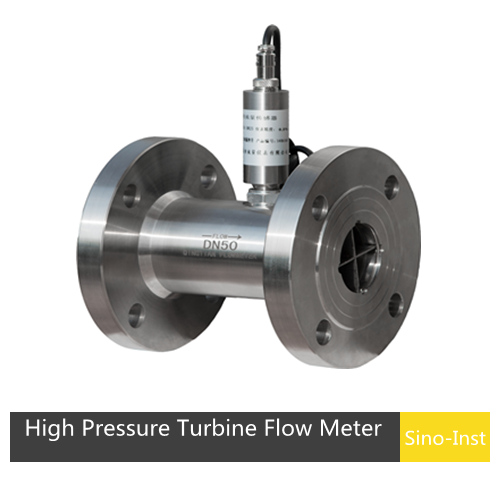
Need to size a turbine flow meter? Are you still only choosing based on pipe diameter? Please stop immediately. Turbine flow meters account for a significant portion of industrial flow measurement processes due to their low cost and wide range of media compatibility.
However, sizing a turbine flow meter is not as simple as just matching the pipe diameter. It also requires considering 10 factors related to actual operating conditions, such as media characteristics, temperature, pressure, and signal output. We hope that by sharing our experience, we can help you choose the most suitable turbine flow meter.
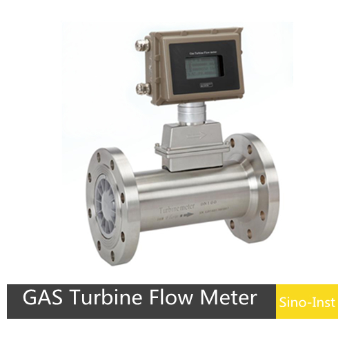
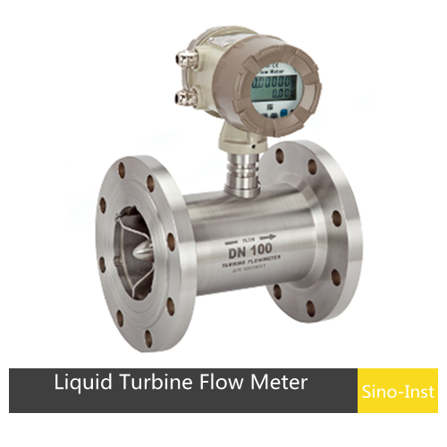
Before sizing a turbine flow meter, we need to confirm the medium being measured. There are two main types of turbine flow meters: gas turbine flow meters and liquid turbine flow meters.
Gas turbine flow meters can measure natural gas (NG), compressed air, nitrogen (N₂), oxygen (O₂), argon (Ar), and other gases without impurities and at low to medium flow rates.
Liquid turbine flow meters can measure liquids such as diesel fuel, water, cryogenic fluids, hydraulic oil, milk, beer, and chemical solutions. They are compatible with small amounts of impurities and low to medium viscosity.
Therefore, the first step in sizing a turbine flow meter is to clearly define the fluid we need to measure. This determines whether we should choose a gas turbine flow meter or a liquid turbine flow meter. The two are not interchangeable.
Furthermore, if the medium is flammable or explosive, the turbine flow meter needs to be explosion-proof.
The pressure inside the pipe significantly affects the flow measurement process. We need to confirm the operating pressure and design pressure.
For gas turbine flow meters, the pressure ratings are generally 1.6 MPa, 2.5 MPa, and 4.0 MPa.
For liquid turbine flow meters, the pressure ratings are 1.6 MPa, 2.5 MPa, 4.0 MPa, 6.3 MPa, 16 MPa, 25 MPa, 32 MPa, and 40 MPa.
The pressure rating of a standard turbine flow meter is 1.6 MPa. Other pressure ratings require custom manufacturing based on the maximum pressure.
In addition to considering the maximum operating pressure, you may also need to consider pressure drop. The pressure drop of a turbine flow meter is relatively small. For example, a DN25 gas turbine flow meter has a pressure drop of approximately 0.6 kPa; a DN25 liquid turbine flow meter has a pressure drop of approximately 35 kPa. If your measurement conditions require specific pressure drop considerations, be sure to consider this in advance.
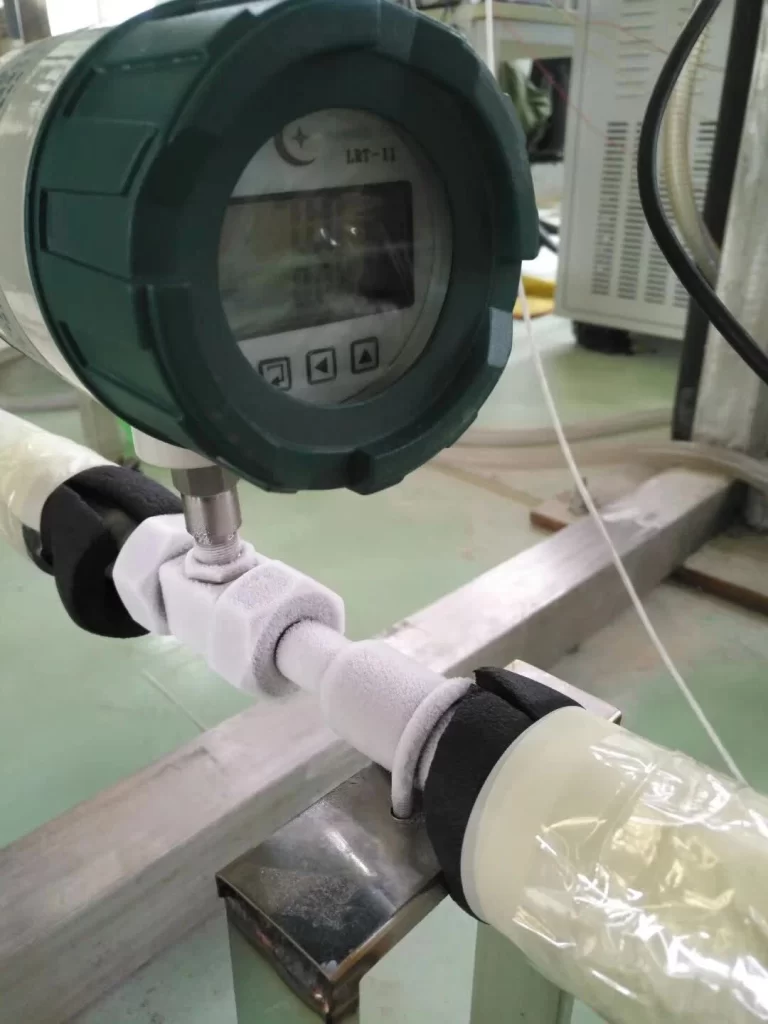
The medium temperature affects the measurement and service life of the turbine flow meter. The measurable medium temperature range for gas turbine flow meters is -30°C to 80°C. The conventional measurement temperature range for liquid turbine flow meters is -20°C to 120°C.
For low-temperature and high-temperature liquids, customized options are available: low-temperature turbine flow meters down to -200°C, and high-temperature turbine flow meters up to 180°C.
Next, we need to confirm the flow range. This includes the minimum flow rate, typical flow rate, and maximum flow rate.
Minimum flow: The lowest steady-state flow rate achievable in the pipeline. We also need to consider the importance of this minimum flow rate and whether it needs to be fully monitored.
Maximum flow: There may be flow surges in the pipeline, reaching peak flow rates. We need to consider whether the turbine flow meter can withstand this flow rate without exceeding its range or being damaged.
Rated flow: This is the typical operating flow rate in the pipeline. At this rated flow rate, the turbine flow meter needs to achieve its highest measurement accuracy.
Step 5: Material Compatibility
The wetted parts of the turbine flow meter must be compatible with the measured medium. Especially when measuring corrosive media, selecting the appropriate material is crucial to prevent corrosion of the flow meter body. The installation environment should also be considered.
Gas turbine flow meters are available in aluminum alloy and 304 stainless steel. If the installation environment has high humidity or the measured gas is corrosive, stainless steel or a gas turbine flow meter with special anti-corrosion treatment should be selected for its good moisture-proof and corrosion-resistant properties.
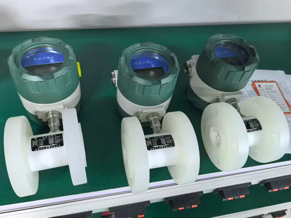
Liquid turbine flow meters offer a variety of material options, including stainless steel, hard alloy, ceramic, fluororubber, and PTFE. For example:
The housing of the turbine flow meter can be made of 304 stainless steel and 316L stainless steel;
The turbine rotor is made of wear-resistant materials such as hard alloy and ceramic to ensure long-term stable performance.
The turbine shaft needs to withstand the rotation of the turbine and the impact of the external medium, so it is usually made of stainless steel or other high-strength materials.
Bearings are used to support the rotation of the turbine. To reduce friction and improve the rotational accuracy and lifespan of the shaft, they are usually made of ceramic or hard alloy materials.
The seals of the turbine flow meter need to ensure the sealing performance and long-term stability of the instrument, so they are usually made of high-temperature and corrosion-resistant materials such as fluororubber and PTFE.
For corrosive liquids, a turbine flow meter body and rotor made of PP material can also be selected.
Step 6: Pipe Diameter
Generally, we can select a turbine flow meter with the same nominal diameter (DN) as the pipe. However, the flow range from Step 4 and the standard measuring range of the turbine flow meter need to be considered.
If a turbine flow meter with the same diameter can fully cover the required flow range, then simply select the flow meter based on the pipe diameter.
If a turbine flow meter with the same diameter cannot fully cover the required flow range, there are two solutions: one is for the user to forgo measuring the lowest or highest flow range. Alternatively, choose a turbine flow meter of a different diameter, which may require modifying the piping.
For example, your pipe is DN25, and the required flow range is 0.9~8 m³/h. The standard measuring range of a DN25 turbine flow meter is 1~10 m³/h. If you directly choose a DN25 turbine flow meter for measurement, the flow rate of 0.9~1 m³/h will be inaccurate. If this flow range is not important to you, you can directly choose the DN25 turbine flow meter.
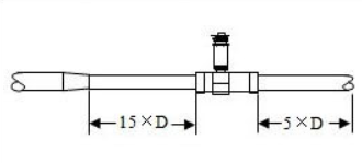
However, if the flow rate of 0.9~1 m³/h is important, then we can consider choosing a DN20 turbine flow meter, whose standard measuring range is 0.8~8 m³/h, which can fully cover the required range. However, a DN20 turbine flow meter and a DN25 pipe cannot be directly matched. Therefore, it is necessary to design and add a reducing pipe section. Refer to the diagram below.
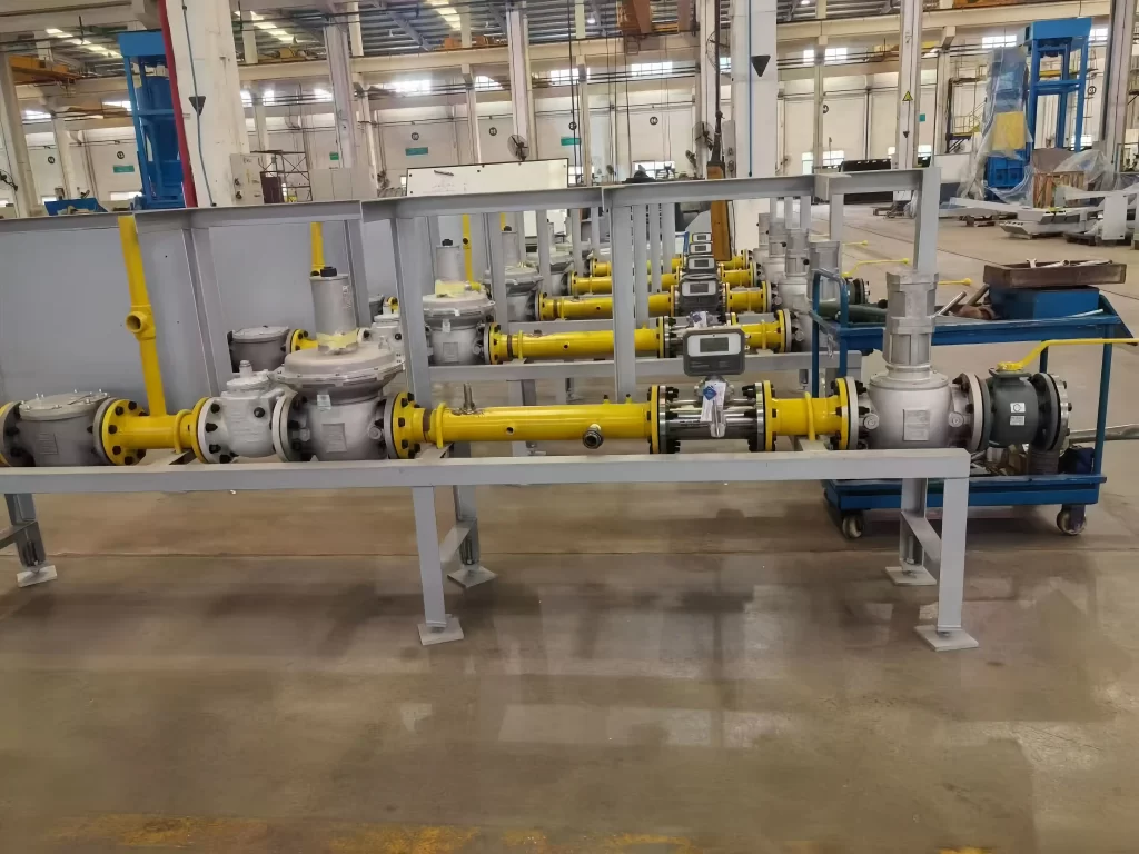
Step 7: Installation Location and Pipe Layout
Turbine flowmeters should be installed in locations where temperature fluctuations are minimal. Choose a location with minimal vibration and impact, and sufficient space for regular inspection of the flowmeter.
Turbine flowmeters are mostly installed horizontally. If installed vertically, the fluid must flow from bottom to top.
Then, the most important consideration is the straight pipe section requirements before and after the turbine flowmeter.
Gas turbine flowmeters require a straight pipe section of ≥2DN upstream and ≥10DN downstream. Liquid turbine flowmeters generally require a straight pipe section of 15DN-20DN upstream and 5DN downstream. If there are valves, elbows, or other special structures, more straight pipe sections are required.
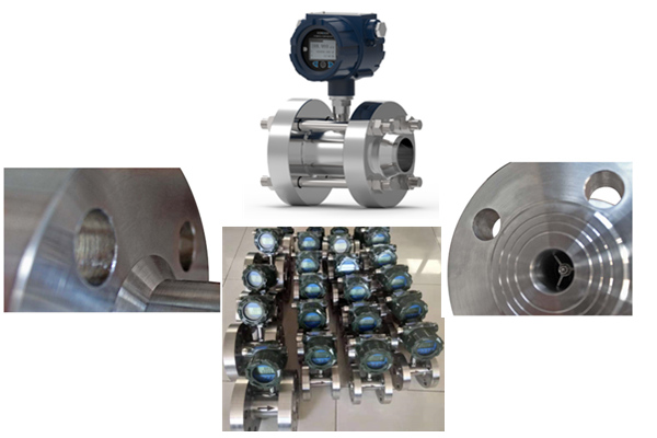
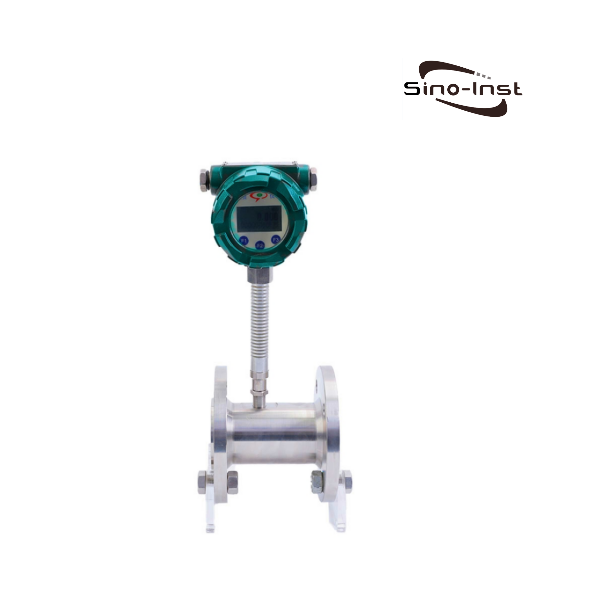
Turbine flow meters generally offer flange, threaded, or clamp connections. When choosing, consider size standards, pressure resistance, and hygienic requirements.
Threaded: For example, G threads, NPT threads, etc. Small-diameter gas turbine flow meters and gas turbine flow meters can be customized with threaded connections.
Flange: Flange connections can withstand higher pressures and offer better sealing. We support customization of various standard flanges such as ANSI, DIN, and JIS.
Tri-clamp (Sanitary Clamp): Easy to disassemble, convenient for cleaning or inspection. This type of sanitary installation is generally required in the food, beverage, and pharmaceutical industries.
Step 9: Signal Output
Turbine flowmeters support pulse, 4-20mA, RS485, and other signal outputs. The choice of signal output needs to be made in conjunction with your back-end monitoring and control equipment. Simply put, if your PLC, DCS system, or flow totalizer can accept a 4-20mA input, then we will configure the turbine flowmeter with a 4-20mA signal.
Step 10: Accuracy Requirements
The typical accuracy of gas turbine flowmeters is ±1.5%R. The typical accuracy of liquid turbine flowmeters is 0.5%, with high-precision models reaching 0.2%. These accuracies are sufficient to meet the measurement requirements of most industries.
Of course, the accuracy of a turbine flowmeter is a comprehensive result of various operating conditions, including the medium, temperature, pressure, and flow rate. By considering all the selection factors discussed in this document, we can maximize the measurement accuracy of the turbine flowmeter.
When it comes to flow measurement, understanding the distinction between mass flow rate and volumetric flow rate is crucial. Both concepts are widely used in various industries, but they differ in several aspects. We’ll explore the key differences between mass flow rate and volumetric flow rate, examine the factors that affect flow rate conversions, and … Read more
What Is the Flow Rate? Is the flow rate the same as Flow? When we choose a flowmeter, we often know the fluid parameters of the pipeline. Including flow range, pressure, pipe diameter, etc. Flow rates and flow ranges are different. Flow is divided into volume flow and mass flow. So what is the relationship … Read more
Hydrogen flow meters are widely used in hydrogen energy fields, such as hydrogen production, hydrogen storage and hydrogen fuel cells. Typically used to monitor volumetric flow, mass flow and usage of hydrogen to ensure proper system operation and optimize performance. Since the value of hydrogen is very high, custody transfer metering is also a very … Read more
A clamp-on ultrasonic flow meter is an instrument that uses high-precision ultrasonic sensing technology to measure flow rate. It mainly consists of a host and a set of ultrasonic sensors. These sensors can be installed on the outer wall of the pipe without the pipe or shutting down the system, and they will not contaminate … Read more
A thermal diffusion flow switch is a flow monitoring device based on the principle of thermal diffusion. It offers superior performance and reliability. Thermal diffusion flow switches have no moving parts. They are durable, have low maintenance costs, and are highly reliable. We, Sino-inst, offer the SI-300C and SI-600 series of thermal diffusion flow switches. … Read more
Industrial Liquid Nitrogen Flow Measurement Solution – Cryogenic Flow Measurement Design. Liquid nitrogen flow meters are a type of cryogenic flow meter specifically designed to measure the flow rate of liquefied nitrogen at extremely low temperatures (-196°C; -320°F; 77 K). Of course, similar cryogenic liquefied media can also be measured, such as LNG, LOX, LAR, … Read more
Top Supplier of Turbine Flow Meters for Oil and Gas Industries
There are many turbine flow meter suppliers on the market, such as Endress+Hauser. We, Sino-Inst, are also a professional manufacturer of turbine flow meters. We provide high-quality gas and liquid turbine flow meters to customers in various countries, including the USA, Singapore, Indonesia, Malaysia, Spain, and others.
As a turbine flow meter manufacturer, we support parameter customization, including material, temperature, and pressure. And we offer better prices!
If you are still unsure which turbine flow meter to choose for your measurement system, please feel free to contact our sales engineers. We will select the most suitable turbine flow meter for you based on your measurement parameters. We support OEM and use international express shipping to deliver the turbine flow meter to your doorstep.
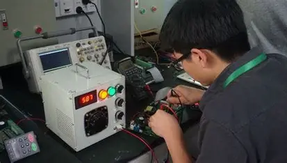
Li Rui is responsible for the R&D and design of the company’s automated instrumentation products, leading the development project of the intelligent pressure transmitter. Start with demand analysis and communicate with the market and customers to obtain key parameters, such as measurement range (0 – 10MPa) and accuracy requirements (±0.1%FS).
Responsible for designing hardware circuits, selecting high-performance microprocessors and pressure sensor chips, and building signal conditioning circuits to achieve accurate signal acquisition and processing. On the software side, he wrote C language programs to implement algorithms such as data linearization and digital filtering, ensuring the stability and accuracy of measurement data. After the product was launched, sales reached 5 million yuan in the first year, with positive market feedback, opening up new market areas for the company.