Home > Blog > Temperature Transmitter Overview | Installation and Calibration
Temperature Transmitter Overview | Installation and Calibration
Temperature transmitters convert input signals from various sensors into standard output signals. Typically, these are 4-20 mA or 0-10 V. Examples include resistance sensors, thermocouples, and potentiometers.
Temperature transmitters connect temperature sensors to subsequent data processing and control systems. It ensures the stability and safety of the production process. Sino-Inst offers a variety of temperature transmitter configuration options. These options include customization of sensor type, transmitter signal, and mounting method.
A temperature transmitter is a device that can convert the temperature signal detected by a temperature sensor into a standard electrical signal output.
The temperature transmitter uses thermocouples and thermistors as temperature-sensing elements. The output signal from the temperature sensing elements is sent to the transmitter module. It is converted into a 4-20 mA current signal, 0-5 V/0-10 V voltage signal, or RS-485 digital signal output that is linearly related to temperature.
Temperature transmitters are primarily used to measure and control temperature parameters. They are widely used for temperature control in power plants, oil and gas, and aerospace technology.
How Does a Temperature Transmitter Work?
The working principle of a temperature transmitter is to convert a temperature variable into a transmittable, standardized output signal. The transmitter’s output signal is then sent to a control device. Such as a loop controller, data logger, or display.
The temperature transmitter serves as the interface between the control system and the temperature sensor. It can isolate, amplify, correct nonlinearity, and convert the sensor’s input signal. It then converts it into a 4-20 mA current signal or a 0-5 V/0-10 V voltage signal that is linearly related to temperature.
Common Temperature Transmitters
Temperature transmitters can be categorized by measurement principle into thermocouple, RTD, and infrared non-contact types.
Based on the output method, they can be classified into analog, digital, and intelligent types.
Based on structural form, they can be categorized into integrated and split types.
The following are our featured temperature transmitters that can be used in various industries:
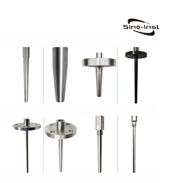
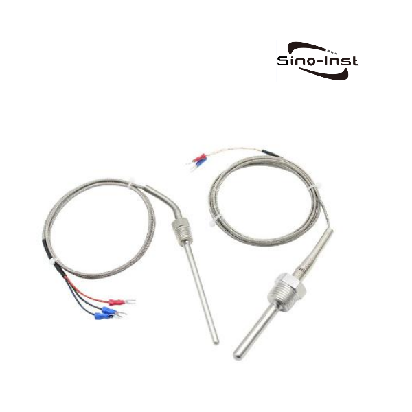
This 4-20mA temperature transmitter can directly measure the temperature of liquids, steam, gases, and solid surfaces within a -200°C to 1300°C range. It is typically used with display instruments, recorders, and computers, and outputs 4-20mA. RS-485/HART protocol customization is supported.
Features
The mechanical transmission components of this digital 4-20mA temperature transmitter are shock-resistant and durable.
It accepts a variety of connection methods.
It saves installation costs for compensation wires and temperature transformers.
It is safe, reliable, and has a long service life.
It features automatic cold junction temperature compensation.
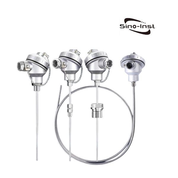
Industrial RTDs are temperature sensors. They can be used to measure and regulate the temperature of liquids, steam, gases, and solid surfaces within a temperature range of -200 to 650°C. When equipped with corrosion-resistant protective tubes, RTDs can also be used in corrosive media.
Features
Industrial RTDs use a compression spring-type temperature sensing element. They offer excellent vibration resistance.
RTDs offer high measurement accuracy.
They can directly contact the object being measured and are unaffected by intervening media.
They have a wide measurement range.
They are simple in structure and easy to use.
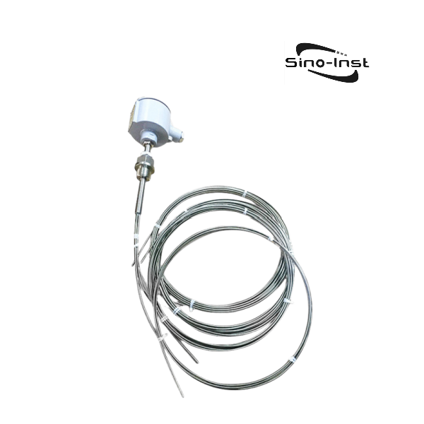
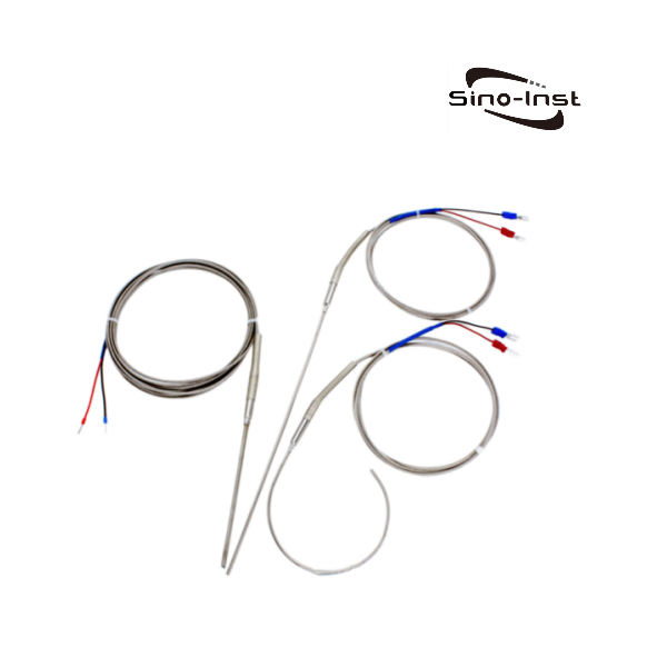
Industrial sheathed thermal resistors are RTD sensors. A sheathed thermal resistor can measure the surface temperature of gases, liquids, and solids within a range of 0 to 1300°C.
Sheathed thermal resistors are used as temperature sensors. They are typically used with display instruments, PLCs, and recording instruments.
Features
The sheathed thermal resistor is enclosed in a stainless steel housing.
It is resistant to high pressure and shock, and has a fast response time.
It has an IP65 protection rating and can withstand harsh operating conditions such as dust and moisture.
It supports a measurement range of 0-1600°C.
It has a service life 3-5 times that of ordinary thermocouples.
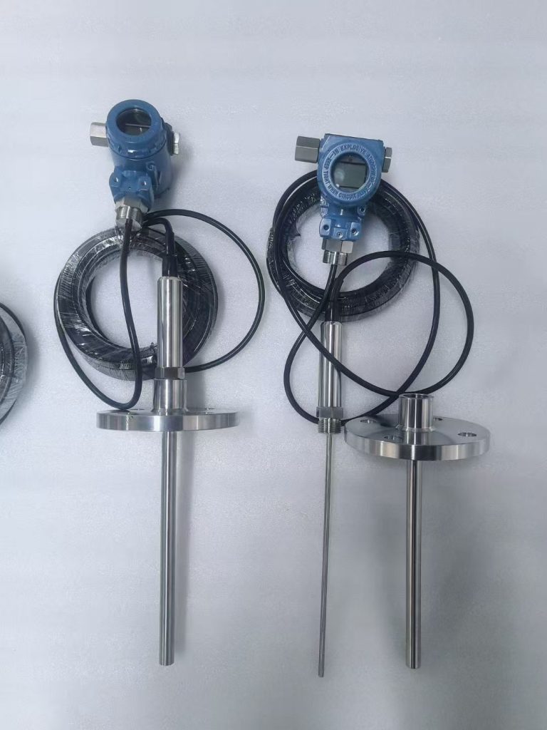
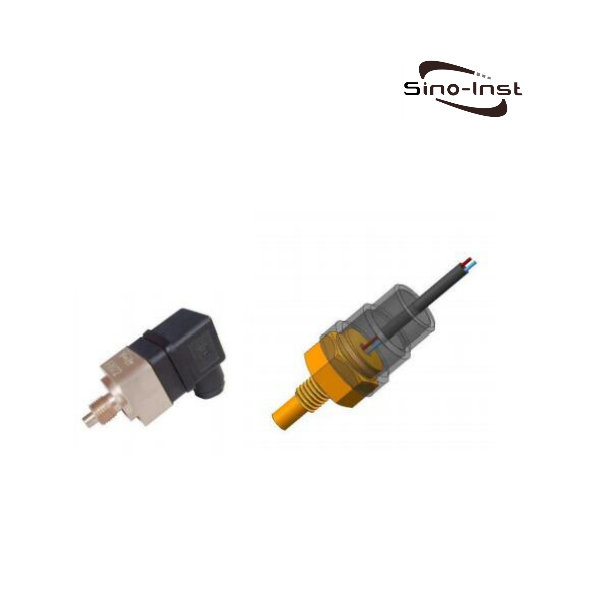
Integrated pressure and temperature transmitters can measure both pressure and medium temperature. The SI-706 pressure-temperature integrated transmitter adopts an integrated temperature-pressure structure. It can simultaneously measure medium pressure and temperature at the same point. It outputs both temperature and pressure signals separately.
Features
Pressure range: -0.1-100 MPa (optional).
Temperature range: -20°C to 85°C (optional), 150°C to 800°C (optional).
Temperature and pressure sensors are integrated into the front panel, providing high frequency response.
This integrated pressure and temperature transmitter features an all-stainless steel construction and a compact design.
Differences Between Temperature Sensors, Temperature Transmitters, and Temperature Switches
Characteristic
Temperature sensors
Temperature transmitters
Temperature switches
Function
It directly measures temperature and converts it into an electrical signal.
It can amplify, linearize, and convert the temperature signal into a standard signal output.
When the temperature reaches the preset value, it can automatically open or close the circuit.
Output Signal
Output resistance or digital signal
Can output current (4-20mA), voltage (0-10V), digital signal (RS485)
Directly trigger the switch action. No standardized signal output.
Structure
It is usually packaged from a single electronic component (such as a thermocouple, thermal resistor). Simple structure.
It consists of a temperature sensor and a conversion module. It has a complex structure.
It is composed of a temperature sensing element and a circuit control module. It can realize temperature triggering action.
Applications
Environmental monitoring, medical equipment
Process data transmission, equipment temperature control
Electrical overheat protection
Customization and Range
Fixed range. Output signal according to the rules
The temperature measurement range can be customized according to the needs. The output signal changes with the range
Preset fixed trigger temperature value. Not adjustable
Installation of Temperature Transmitters
1. Confirm device parameters
Check whether the transmitter power supply voltage, input signal, and output signal match the system.
2. Select installation location
The installation location should avoid strong electromagnetic interference or high-temperature areas. Ensure good heat dissipation conditions. Some models require additional heat dissipation devices.
3. Sensor connection
For three-wire systems, connect the individually colored wires to terminals 11, and connect wires of the same color in parallel to terminals 9 and 10. The positive terminal of the thermocouple (TC) should be connected to terminal 10.
4. Power supply and output wiring
Connect the power supply wires to terminals 1 (positive) and 2 (negative), ensuring correct polarity. Connect the output signal wires to the PLC or controller according to system requirements. For example, a 4–20 mA output corresponds to the remote control terminal.
5.Pipe Mounting
Drill a hole in the pipe according to the flange or threaded base size, weld the base, and then tighten the transmitter. Some models can be mounted on a standard DIN rail using spring clips.
How to Calibrate a Temperature Transmitter?
1. Equipment Preparation
Device calibration requires a millivolt signal generator, a precision resistance box, and a standard potentiometer. Simulate thermocouple/RTD signal input.
2. Classification Operation
Thermocouple Type: The input signal must take cold junction compensation into account. The formula is Ei = E(t, 0) − E(t0, 0), Ei = E(t, 0) − E(t0, 0).
Thermocouple Type: A resistance box simulates the resistance values corresponding to different temperatures and directly adjusts the output signal.
3. Calibration Process
Zero Calibration: Enter the lower limit value (e.g., 0°C). Adjust until the output reaches 4 mA.
Span Calibration: Enter the upper limit value (e.g., 1300°C). Adjust until the output reaches 20 mA.
Full Span Verification: Select at least 5 evenly distributed points. Perform three forward and reverse travel tests and record the deviations.
4. Environmental Requirements
The calibration environment temperature must be maintained between 15°C and 25°C. Humidity must be between 40% and 70%.
5. Wiring Specifications
We must ensure correct polarity. Thermocouples must distinguish between positive and negative terminals. Thermistors use a three-wire system to minimize errors.
RTD temperature sensors are small devices. They are commonly used for temperature measurement in a variety of industrial applications. These sensors are more accurate and stable than thermocouples and other temperature probes. They are widely used in various industries, including automotive, aerospace, and food processing. When you need accurate and repeatable temperature readings, Sino-Inst’s RTD … Read more
In explosive and flammable industrial environments, safety and operational efficiency are paramount. Temperature monitoring is not only a routine operation but also the cornerstone of safe production. Therefore, explosion-proof temperature sensors are a core component in this field. Explosion Proof Temperature Sensors offer extremely high accuracy and reliability. They are suitable for industries such as … Read more
Industrial Temperature Monitoring System can detect and record temperature changes. Temperature sensors are installed on key equipment, pipelines, furnaces, etc. in the factory to monitor temperature changes during equipment operation in real time. The data detected by the sensor can be transmitted to the inspection meter, recorder, and even to the cloud platform through the … Read more
When fluids are exposed to extreme temperatures (extremely high and extremely low), meticulous measurement of fluid flow is critical. This is where extreme temperature flow meters come into play. Extreme temperature applications require proper protection of the sensitive electronic components inside the flow meter. In addition, since the viscosity of the heat transfer fluid changes … Read more
Low temperature flow meters designed to measure fluid flow accurately under cold conditions, are critical for ensuring efficiency, safety, and product quality. Most cryogenic fluids are converted into liquids by reducing the temperature of gas to a very low temperature. For example, we often see cryogenic liquid nitrogen and liquid oxygen. Not every flow meter … Read more
High temperature and high pressure type pressure measurement is an extremely harsh measurement. Usually, the temperature is higher than 80℃, or the pressure is higher than 60MPa, which exceeds the measurement range of conventional pressure transmitters. Sino-Inst supports providing you with customized solutions for various high temperature and high pressure measurement parameters. Customized case The … Read more
The principle of temperature compensation and pressure compensation of the flow meter is based on the changes in physical parameters such as density and viscosity of the fluid at different temperatures and pressures, which affects the measurement accuracy of the flow meter. In order to eliminate this effect, temperature and pressure compensation is required. When … Read more
Industrial temperature sensors and temperature transmitters convert medium temperature into output signals. These can be resistance signals (PT100/PT1000), current signals (4-20mA), or digital signals.
Our 4-20mA temperature transmitters can be configured with PT100, K-type, N-type, and J-type thermocouples. They are suitable for use in harsh environments. Explosion-proof models include EXdⅡBT4, dⅡCT5, and dⅡCT6.
Sino-Inst offers over 50 industrial temperature sensors and transmitters. These include RTDs, thermocouples, PT100s, thermowells, and more. We also support customizable parameters to meet your industrial process application needs!
If you need to purchase explosion-proof temperature sensors or have any questions, please feel free to contact us.
Zhang Wei, possesses 20 years of experience as an automation instrumentation engineer, specializing in the research, design, installation, commissioning, and maintenance of automation instruments.
Face to various instrument communication protocols (such as Modbus, Profibus, etc.), with solid hardware circuit design and software programming skills (proficient in C language and PLC programming). Has extensive project experience; projects he has led and participated in have all achieved outstanding results, improving product accuracy, reducing costs, and increasing production efficiency.
Possesses excellent communication and coordination skills and a strong team spirit, enabling him to quickly respond to customer needs and provide high-quality automation instrumentation solutions.