Use and Maintenance of Coriolis Mass Flowmeters
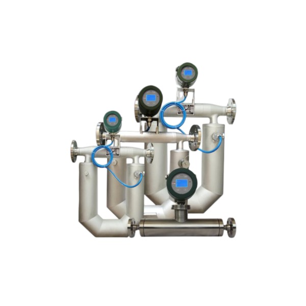
Coriolis mass flowmeters are leading precision flow and density measurement solutions, enabling the most accurate and repeatable mass measurement of liquids or slurries. Proper installation, proper use, and proper maintenance of Coriolis mass flowmeters ensure excellent performance, even in harsh operating environments.
Coriolis Flow Meter Upstream Downstream Requirements
First, mass flowmeters generally have lower requirements for straight pipe lengths. This is a major advantage over other flowmeter types (such as vortex flowmeters, orifice plates, and electromagnetic flowmeters). Under most favorable operating conditions, there’s no need for straight pipe sections upstream or downstream of the Coriolis mass flowmeter to regulate flow.
This is primarily because Coriolis mass flowmeters directly measure the mass flow rate of the fluid. Based on the phase difference of the fluid’s vibrations, they are less affected by flow velocity distribution. They are not limited by the Reynolds number and are less sensitive to the fluid’s laminar/turbulent flow regime.
Read more about: Coriolis Mass Flow Meter Technology
Special installation situations that may require a straight pipe section:
Gas-liquid two-phase flow: If the fluid contains bubbles or does not fill the pipe, measurement accuracy may be affected. It is recommended to reserve a certain amount of straight pipe upstream of the flowmeter (e.g., 5D to 10D, where D is the pipe diameter) or install a gas-liquid separator.
Severe pulsating flow: For example, frequent starts and stops of pumps or valves can cause flow fluctuations. A buffer device or a straight pipe section may be added upstream to stabilize the flow pattern.
Asymmetric installation: If there are disturbance sources such as elbows or reductions near the flowmeter, it is recommended to reserve 3D to 5D of straight pipe upstream (refer to the manufacturer’s specifications for details).
Basic Requirements for Coriolis Mass Flowmeters Installation
- The mass flowmeter sensor should be installed so that the sensor flow direction mark is consistent with the fluid flow direction;
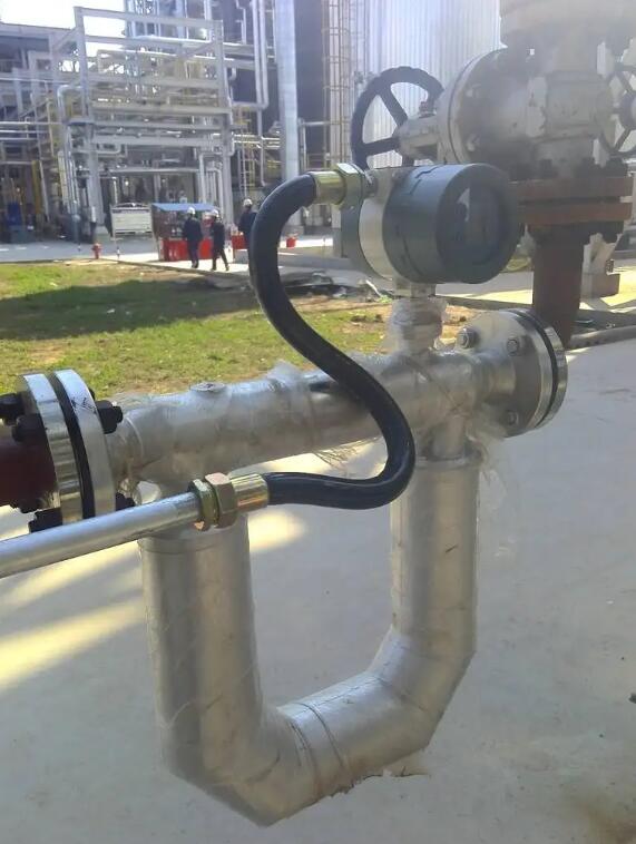
- The Coriolis mass flowmeter is a flow meter measured according to the principle of measuring tube vibration. Therefore, when installing the sensor, the relevant pipeline should be considered as a solid support. Avoid vibration of the instrument and related pipelines;
- If strong pipeline vibration is unavoidable, it is recommended to use flexible pipes to isolate the pipeline system from the instrument sensor;
- When installing, the connecting flange surfaces should be parallel to each other, so that the centers of the two flanges are on the same axis to avoid additional stress;
- When measuring liquid flow, the fluid flow direction should be from bottom to top as much as possible, and at the same time, the instrument should be avoided to be installed at the highest point of the pipeline to prevent gas accumulation in the pipeline from affecting the normal operation of the instrument.
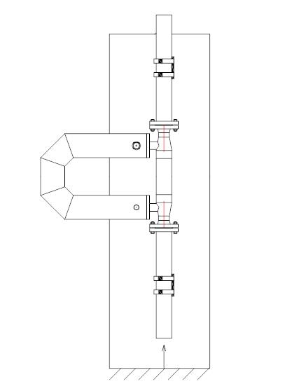
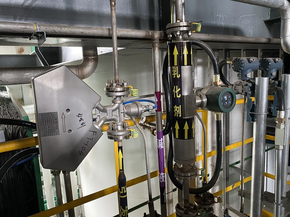
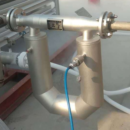
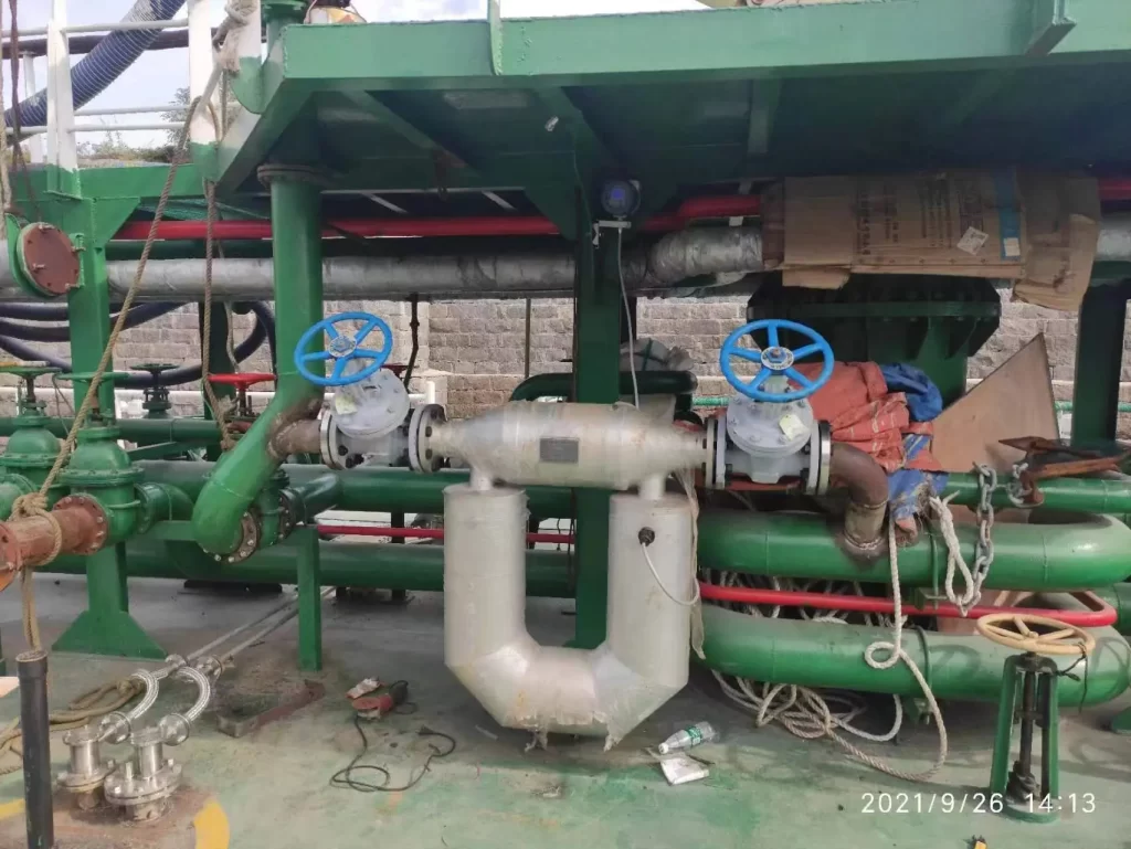
Installation Orientation for Coriolis Mass Flowmeters
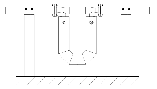
The basic principle of flow sensor installation is to ensure that the vibrating tube in the sensor works in a vertical state. The vibrating tube of the flowmeter can be installed vertically downwards, vertically upwards, or flag-type installation or inclined flag-type installation.
But be sure to avoid horizontal installation. At this time, the vibrating tube is not only affected by the Coriolis force. It is also affected by the gravity of the vibrating tube, so that the measurement cannot be carried out normally.
In general, when measuring the flow rate of liquid medium, the vibrating tube should be installed vertically downward. In order to avoid the gas volume in the vibrating tube and affect the normal measurement.
In general, when measuring the flow rate of gas medium, the vibrating tube should be installed vertically upwards, so as to avoid the liquid volume in the vibrating tube and affect the normal measurement.
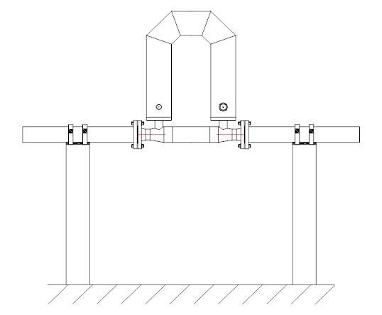
If there may be particles accumulated in the vibrating tube in the measurement medium, the flag installation method should be adopted to avoid the accumulation of particles in the vibrating tube and affect the normal measurement.
Use and Maintenance of Coriolis Mass Flowmeters
Coriolis Flow Meter Wiring Diagram
The back of the Sino-Inst mass flowmeter’s display housing houses the junction box. Opening the rear cover reveals a terminal block. The lower end of the converter housing provides access holes for sensor leads.
The converter has two terminal blocks: a basic power supply terminal block (the instrument’s basic power supply is 24VDC) and an auxiliary power supply terminal block (the auxiliary power supply is 220VAC).
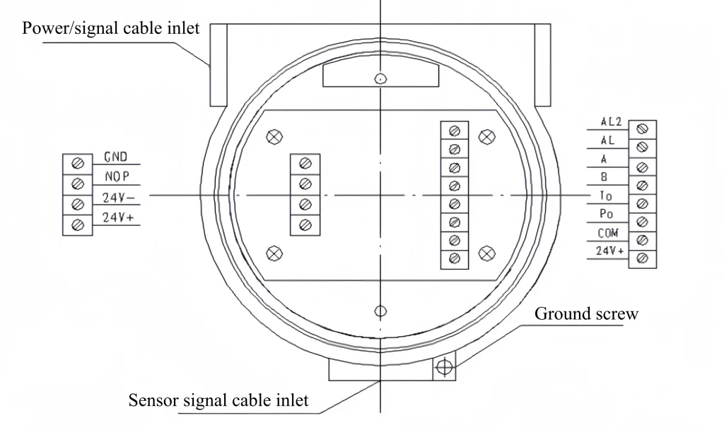
Basic Power Supply Terminal Block Structure:
The basic power supply terminal block has two rows of terminals, four on the left and eight on the right. The left terminals are for power, and the right terminals are for signals. The terminal blocks are shown in the figure below:
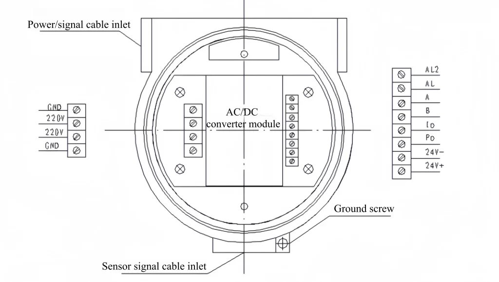
Auxiliary Power Supply Terminal Block Structure:
When using a 220VAC power supply, auxiliary power supply terminals are installed on the instrument’s wiring side. The auxiliary power supply terminal block houses the power conversion module in the center, with terminals on both sides. The left terminals are for power, and the right terminals are for signals. The terminal blocks are shown in the figure below:
Zero Calibration of the Mass Flow Meter
Installation stress may be generated during the initial installation of the flowmeter, which may cause the zero point of the flowmeter to change and cause measurement errors. Therefore the flowmeter zero must be checked after the initial installation of the flowmeter. If the zero point changes, the zero point correction operation should be carried out.
Preparations for zero point calibration include:
- The flowmeter is preheated, and the sensor is wetted with the measured medium to make its temperature close to the normal working temperature;
- Then stop the medium flow (close the valves on both sides of the flowmeter) to ensure that the sensor is in a full pipe state;
- Wait for 3 to 5 minutes to ensure that the fluid completely stops flowing;
- Take measures to ensure that the pipeline and sensor are in a static state. Prevent pipeline vibration from affecting the correct zeroing process.
Carry out the zero point calibration operation according to the instructions of the zero point calibration operation in the manual of the converter. At this time, the indicator light is displayed, indicating that the zero point calibration is in progress (the zero point operation lasts for a few seconds). Until the status indicator light goes out, the instrument displays normally. The instrument is zero End, this process takes about tens of seconds.
Maintenance of the Mass Flow Meter
Due to its structural characteristics, the mass flowmeter generally does not require special maintenance during use.
However, in some special use conditions, appropriate maintenance measures should be taken to ensure the accurate and reliable operation of the flowmeter.
E.g:
- When there are particles in the fluid that may accumulate in the vibrating tube, they should be checked and eliminated regularly so as not to affect the normal use of the flowmeter;
- When the measuring medium may adhere to the inner wall of the vibrating tube, it should be purged regularly so as not to affect the normal use of the flowmeter;
- When there are particles in the measurement medium and the vibrating tube may be worn, it should be checked and dealt with in time.
Coriolis Flow Meter Troubleshooting
During the initial installation and use, if the flowmeter is found to be working abnormally, the cause of the failure should be determined.
The cause of failure can be divided into two types: application problems and flow meter system problems.
The application problem is more complicated. For example, the measurement fluctuation error caused by the process and the state change of the medium should be analyzed according to the actual situation.
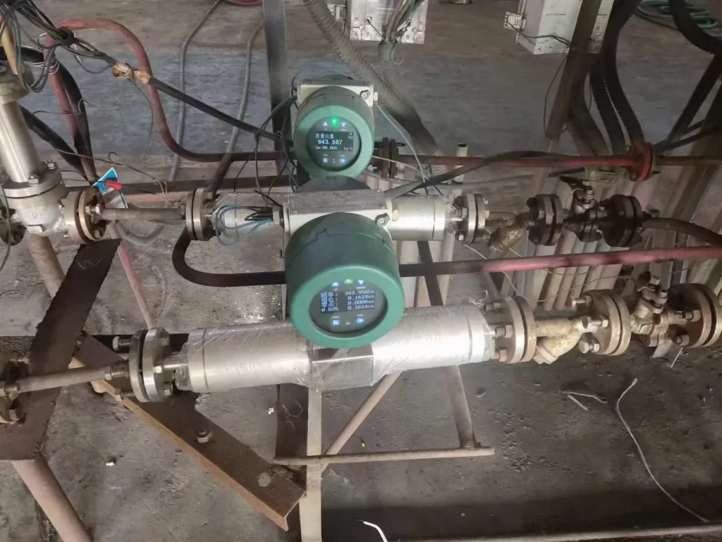
For the fault diagnosis of the flowmeter, the user can use the LED indicator light on the panel and the LCD display. The different colors of the LED indicator light represent the working status of the flowmeter, which is convenient for the user to check the working status. The LCD display can display the alarm of the transmitter self-diagnosis information, which is helpful for users to judge and define faults.
Common Troubleshooting Table
| Fault phenomenon | cause of issue | Solution |
| Large zero point drift | 1. Whether the medium in the flowmeter is full and does not flow. | 1. Make the flowmeter full pipe by feeding or other methods, and close the valves at both ends of the flowmeter |
| 2. Whether the installation pipeline of the flowmeter is fixed, and whether there is any interference such as a strong vibration source or a frequency converter nearby | 2. Add support or switch to hose connection | |
| 3. The sensor is installed with stress | 3. The connecting pipeline and the sensor interface should be on the same axis | |
| Instantaneous flow display is abnormal | 1. Whether the actual flow of the pipeline exceeds the maximum range set by the instrument. | 1. Reduce the聽pipeline flow聽or reset the maximum flow of the flowmeter |
| 2. Whether there is strong vibration in the connecting sensor pipeline. | 2. Add support or switch to hose connection | |
| 3. Check whether the zero point of the flowmeter is normal. | 3. When the calibration conditions are met, calibrate the zero point. | |
| 4. Check the F0 and DP values of the meter to judge whether the meter is working normally. | 4. The meter is not working properly, please contact the manufacturer for after-sales service | |
| Density display is unstable | 1. Check whether the F0 value is normal through the LCD screen or communication software (normal value > 50Hz, and the value is stable) | 1. Whether there are air bubbles in the pipeline, and find out the cause of the air bubbles (such as the installation position of the regulating valve is not correct) |
| 2. Check whether the sensor pin parameters are normal | 2. If it is abnormal, contact the manufacturer for after-sales service | |
| Meter does not show | 1. Is the instrument power supply normal? | Check the power supply voltage and terminals to ensure that the 24V power supply is working properly |
| 2. Measure whether the 24V power supply of the wiring board is normal | ||
| Communication no signal | Check whether the communication line is reversed or short-circuited | Check the wiring or switch wiring between A and B |
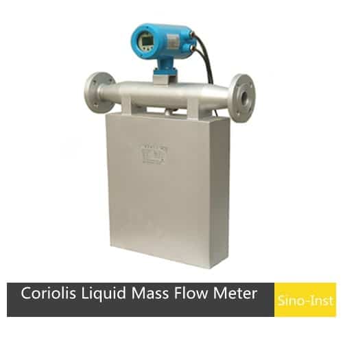
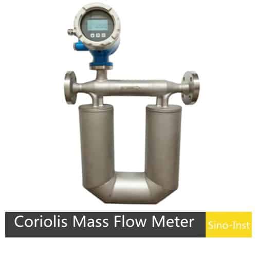
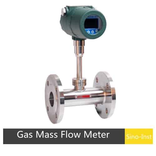
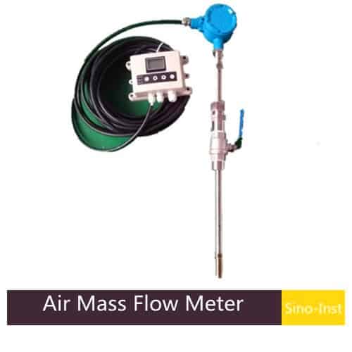
Featured Mass Flow Meters
Read More
Liquid mass flowmeters, as high-precision flow measurement tools, play a vital role in industrial production. Their operating principle, based on thermophysical properties or vibration, directly measures the change in mass of a liquid as it flows through the sensor, eliminating the need for conversion to volumetric flow, thus ensuring accurate and reliable measurement.
They are primarily used to measure the mass flow, total volume, and density of a medium. They can also measure volumetric flow, total volume, medium temperature, moisture content, alcohol content, the concentration of two liquids mixed evenly, and the ratio of raw materials in a process flow.
Main applications:
- In chemical production, they precisely control the addition of reactants to ensure product quality.
- In the petroleum industry, they are used for oil metering and trade settlement to ensure fair trade.
- In the papermaking industry, such as pulp metering and the textile printing and dyeing industry.
- In the environmental protection industry, such as wastewater treatment.
- In the desulfurization process, they measure slurry density.
Pressure drop refers to the irreversible pressure caused by a fluid overcoming resistance. Because Coriolis mass flowmeters have complex tube configurations and varying degrees of constriction, pressure drop is a crucial parameter that cannot be ignored in actual use.
The pressure drop of a mass flowmeter is dependent on the fluid’s properties, flow conditions, and the structural parameters of the mass flow sensor. Once the fluid’s density, viscosity, and flow rate are determined, the flowmeter’s pressure drop is solely dependent on its structure, specifically, parameters such as the diameter, flow area, and measuring tube shape.
Sino-Inst offers mass flowmeters of various sizes and can calculate the pressure drop at different flow rates based on your operating parameters.
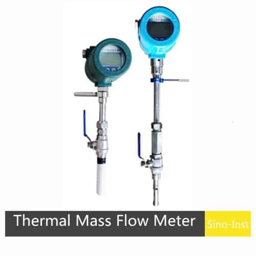
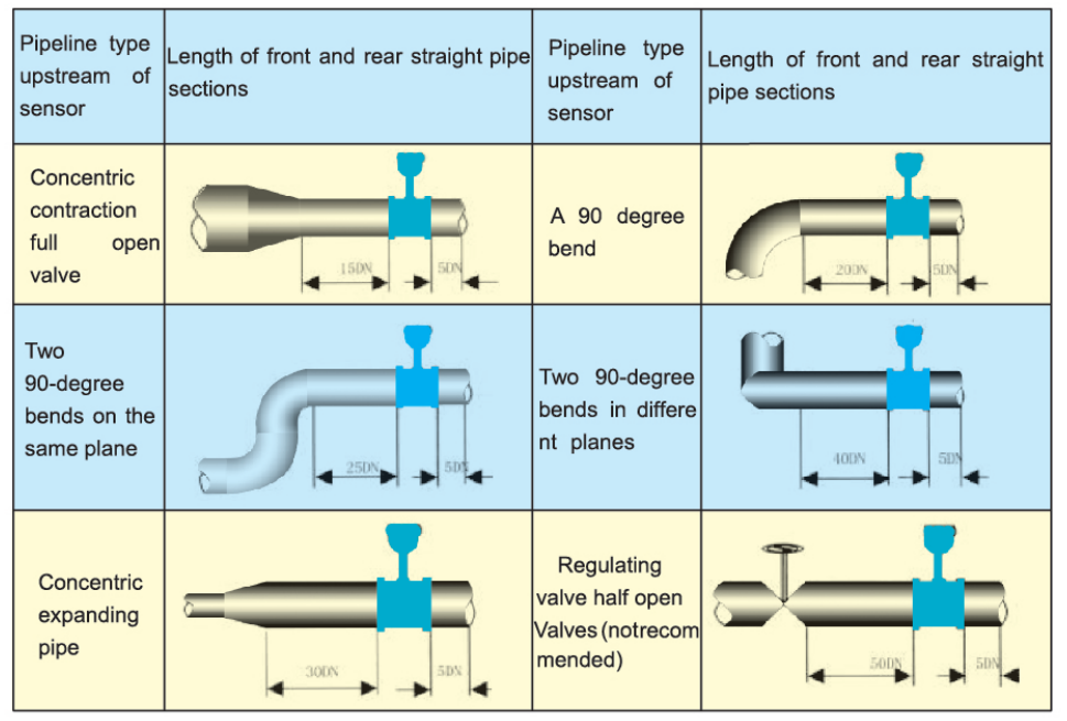
When installing a thermal mass flowmeter, avoid elbows, obstructions, reducers, and valves to ensure a stable flow field. Long upstream and downstream straight pipes are required, with the upstream straight pipe length exceeding 10D and the downstream straight pipe length exceeding 5D.
When the straight pipe section requirements cannot be met on site, a gas rectifier can be connected in series to significantly reduce the straight pipe section requirements.
The following diagram illustrates the required straight pipe lengths for several commonly encountered field situations:
Sino-Inst, as a manufacturer of Coriolis mass flowmeters. The Coriolis Mass Flowmeters we supply have high measurement accuracy, and the measurement is not affected by the physical properties of the medium. There is no requirement for the length of the upstream and downstream straight pipe sections.
Coriolis mass flowmeter is a highly intelligent instrument. In addition to displaying and outputting mass flow rate, its transmitter can also output process parameters such as volume flow rate, density, temperature, viscosity and concentration converted into 4mA~20mA signal, pulse signal or bus signal.
Therefore, Coriolis mass flowmeters are widely used in chemical, pharmaceutical, energy, rubber, paper, food and other industrial sectors, and are quite suitable for proportioning, loading and custody transfer.

Zhang Wei, possesses 20 years of experience as an automation instrumentation engineer, specializing in the research, design, installation, commissioning, and maintenance of automation instruments.
Face to various instrument communication protocols (such as Modbus, Profibus, etc.), with solid hardware circuit design and software programming skills (proficient in C language and PLC programming). Has extensive project experience; projects he has led and participated in have all achieved outstanding results, improving product accuracy, reducing costs, and increasing production efficiency.
Possesses excellent communication and coordination skills and a strong team spirit, enabling him to quickly respond to customer needs and provide high-quality automation instrumentation solutions.