Home > Blog > Static Torque vs Dynamic Torque: A Practical Guide to Selecting the Right Sensor in 2026
Static Torque vs Dynamic Torque: A Practical Guide to Selecting the Right Sensor in 2026
The distinction between static and dynamic torque represents a fundamental division in the field of mechanical measurement and engineering. Static torque, often termed reaction torque, pertains to the rotational force applied to an object that does not produce angular acceleration. It is the force of twisting or turning against a fixed resistance. Conversely, dynamic torque involves the measurement of rotational force on a moving or rotating component, such as a driveshaft or motor.
The accurate quantification of these forces is paramount across numerous industries, from automotive engineering and aerospace to robotics and manufacturing.
Imagine you are trying to loosen a very stubborn lid on a jar. You grip the lid firmly and twist. That twisting force you apply with your hand is torque. It is not just a straight-line push or pull (which we call linear force); it is a force with a rotational intention. This rotational equivalent of linear force is what makes wheels turn, propellers spin, and wrenches tighten bolts.
The Physics of Rotational Force
In the language of physics, torque (represented by the Greek letter tau: τ) is defined as the product of the magnitude of the force (F) applied and the perpendicular distance from the axis of rotation to the point where the force is applied (r). This distance is often called the lever arm. The equation is elegantly simple: τ = r × F.
What does this mean in practice? A longer wrench makes it easier to loosen a tight nut because the extended handle increases the lever arm, allowing you to generate the same torque with less physical effort. This principle is fundamental to almost every mechanical system that involves rotation. Torque is typically measured in units like Newton-meters (N·m) or foot-pounds (ft·lb).
Static Torque vs Dynamic Torque: The Core Distinction
The world of torque measurement is largely divided into two domains: static and dynamic. The difference is not in the torque itself, but in the state of the object to which the torque is being applied.
Static Torque is measured when the rotational force does not result in angular acceleration. This might sound complex, but the concept is straightforward. Our stubborn jar lid, before it starts to turn, is an example of a static torque system. You are applying a torque, but the lid is resisting and not rotating. The force is in equilibrium. This stationary or non-rotating torque is also commonly known as reaction torque.
Dynamic Torque, on the other hand, is the torque measured on a rotating object. Imagine the driveshaft of a car. As the engine runs, it applies a torque to the driveshaft, causing it to spin and deliver power to the wheels. Measuring the torque in this spinning shaft is a dynamic torque measurement. It is the torque associated with motion and power transmission.
Think of it this way: static torque is about the potential for rotation against a fixed object, while dynamic torque is about the actual force maintaining rotation in a moving object. This single distinction—rotation or no rotation—is the most important factor in deciding what kind of measurement approach and what type of sensor you will need.
Static Torque (Reaction Torque): The Force of Stillness
Static torque, or reaction torque, is the measure of a twisting force that is being resisted, resulting in a state of equilibrium where no rotation occurs. It is the silent partner to Newton’s third law—for every action, there is an equal and opposite reaction. When you tighten a bolt, the torque you apply with the wrench is the action; the resistance from the bolt and the clamped material creates an equal and opposite reaction torque. Measuring this reaction torque is often simpler than measuring its dynamic counterpart, but it is no less important for ensuring safety and functionality in a vast number of applications.
Defining Reaction Torque
Let’s build a clearer mental model. Consider a large electric motor bolted to the floor. When the motor is turned on, its internal rotor begins to spin. This spinning action creates a torque on the motor’s shaft (the “action” torque). Simultaneously, the motor’s housing tries to rotate in the opposite direction due to the reactive force. Because the housing is bolted down, it cannot rotate. The force it exerts on its mounting bolts is the reaction torque.
By placing a reaction torque transducer between the motor housing and its fixed mount, we can precisely measure this force. Since the action torque and reaction torque are equal and opposite (barring any frictional losses), measuring the stationary reaction torque gives us an accurate value for the active torque being produced by the motor, all without needing to touch the spinning shaft itself. This indirect measurement method is a cornerstone of many testing and monitoring systems.
How Static Torque Measurement Works
The most common device used for this purpose is a static torque sensor, also known as a reaction torque transducer. At the heart of most of these sensors is a precisely machined metal element called a strain gauge.
A strain gauge is a very thin, foil-like electrical conductor arranged in a grid pattern. It is bonded securely to the surface of the sensor’s structural body. When a torque is applied to the sensor, the metal body deforms or flexes ever so slightly. This deformation, though microscopic, stretches or compresses the strain gauge bonded to it.
The stretching or compressing changes the electrical resistance of the foil conductor. This change in resistance is directly proportional to the amount of torque applied. The sensor’s internal electronics, typically arranged in a configuration called a Wheatstone bridge, can detect this minute change in resistance with incredible precision. The electronics then convert this change into a calibrated electrical signal, such as a voltage or current, that can be read by a data acquisition system or display. Because nothing is rotating, there are no complex parts like slip rings or bearings needed to transmit the signal, making static torque sensors robust, reliable, and cost-effective.
Common Applications of Static Torque Measurement
The measurement of reaction torque is foundational to quality control, safety testing, and process automation in many fields.
Fastener Tightening: In automotive assembly, aerospace, and construction, bolts must be tightened to a specific torque specification. Over-tightening can damage the threads or the parts being joined, while under-tightening can lead to loosening under vibration, which could be catastrophic. Automated torque wrenches and screwdrivers use integrated static torque sensors to apply and verify the correct torque on every fastener.
Material and Component Testing: How much twist can a drill bit handle before it breaks? At what torque does a cap on a medicine bottle fail? Static torque sensors are used to answer these questions. They are used in torsion testing machines to determine the strength, stiffness, and failure points of materials and finished products.
Valve Actuation: Many industrial processes rely on valves to control the flow of liquids or gases. Static torque sensors can be used to monitor the torque required to open or close a valve. A sudden increase in the required torque might indicate a blockage or a failing valve, allowing for proactive maintenance before a failure occurs.
Robotics and Haptics: In advanced robotics, force/torque sensors at a robot’s joints or “wrist” measure the reaction forces encountered by the robotic arm. This allows the robot to “feel” its environment, enabling it to perform delicate tasks like assembling electronics or safely interacting with humans.
Dynamic Torque (Rotating Torque): The Force in Motion
While static torque deals with forces in equilibrium, dynamic torque plunges us into the world of motion. Dynamic torque, often called rotating torque, is the measurement of the twisting force in a rotating shaft or component. This is the torque that does the actual work in a system—the torque that turns a car’s wheels, spins a generator’s turbine, or mixes ingredients in an industrial blender. Measuring this torque is essential for understanding a machine’s power, efficiency, and real-time performance.
Defining Rotating Torque
Power, in a rotational system, is a function of torque and rotational speed. The formula is: Power = Torque × Angular Velocity. This simple relationship highlights why rotating torque measurement is so valuable. If you can accurately measure the torque on a spinning shaft and you know how fast it is spinning (in revolutions per minute, or RPM), you can calculate the exact amount of power being transmitted through that shaft at any given moment.
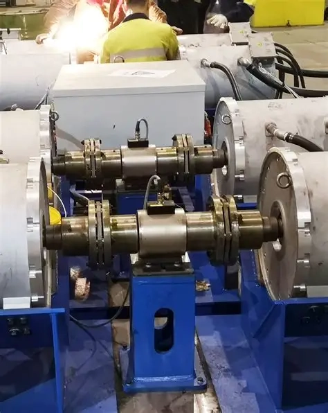
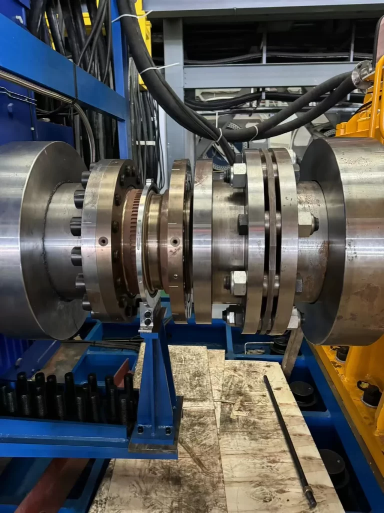
Imagine an engineer testing a new car engine on a dynamometer (or “dyno”). The engine is connected to a braking unit via a driveshaft. A dynamic torque sensor is installed as part of this driveshaft. As the engine runs through its RPM range, the sensor measures the torque it is producing in real time. By combining this data with the engine’s speed, the engineer can generate a complete power curve, showing exactly how the engine performs under different conditions. This data is indispensable for tuning, design optimization, and efficiency analysis.
Challenges in Rotating Torque Measurement
Measuring torque on a spinning object presents a significant engineering challenge that is not present in static measurements. The core problem is twofold: how do you get an excitation voltage to the sensor’s strain gauges on the rotating shaft, and how do you get the measurement signal from the rotating shaft back to the stationary data acquisition system? Engineers have developed several clever solutions to this problem, which generally fall into two categories: contact and non-contact methods.
Principle
Measures reaction force on a stationary body. No rotating parts.
Measures torque on a rotating shaft.
Motion
Zero or near-zero angular motion.
Continuous angular rotation.
Construction
Simple, robust body with strain gauges. Wires connect directly.
Complex assembly with rotating and stationary parts.
Signal Transfer
Direct wiring.
Slip rings, rotary transformers, or telemetry (non-contact).
Typical Use Cases
Bolt tightening, valve testing, material torsion tests, motor braking.
The ability to measure torque in motion is key to optimizing and controlling a wide range of machinery.
Engine and Motor Testing: As mentioned, dynamometers are a primary application. They are used to test everything from small electric motors to massive marine diesel engines, providing critical data on power output, fuel efficiency, and mechanical health.
Drivetrain and Gearbox Analysis: In automotive and industrial applications, dynamic torque sensors are placed on shafts before and after a gearbox to measure its efficiency. By comparing the input torque to the output torque, engineers can quantify power losses within the system and identify potential problems like worn gears or bearings.
Pump and Compressor Monitoring: In process industries, large pumps and compressors are often critical assets. A dynamic torque sensor on the drive shaft can monitor the load in real time. An unexpected change in torque could indicate a change in fluid viscosity, a blockage in a pipe, or an impending mechanical failure, allowing operators to intervene.
Marine Propulsion Systems: On ships, measuring the torque on the propeller shaft is used to calculate the engine’s power output and optimize fuel consumption. It also helps in detecting issues with the propeller, such as damage or fouling, which can significantly impact efficiency.
Static Torque Sensor vs. Dynamic Torque Sensor
Having established the conceptual difference between static and dynamic torque, we can now examine the specific hardware designed to measure them. The choice between a static torque sensor and a dynamic torque sensor is the most fundamental decision in configuring a torque measurement system. Their designs are fundamentally different, optimized for the unique challenges of measuring stationary versus rotating forces.
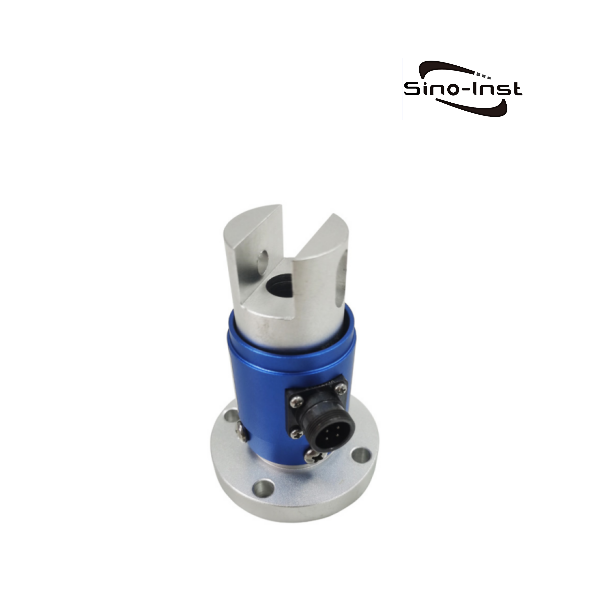
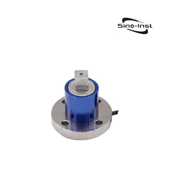
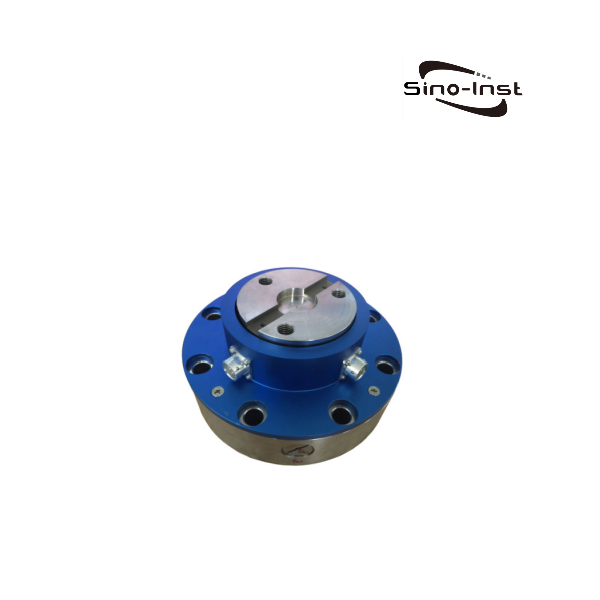
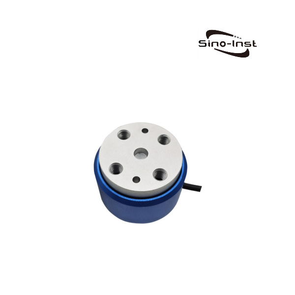
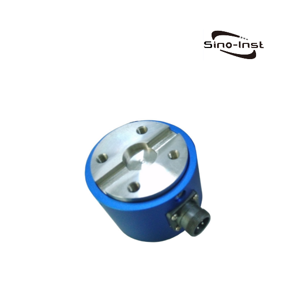
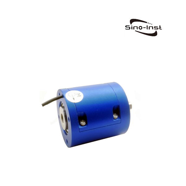
Reaction Torque Transducer: Anatomy and Principles
A reaction torque transducer is the quintessential tool for static torque measurement. Its design prioritizes rigidity, stability, and simplicity.
Structure: Typically, it consists of a solid metal body, often shaped like a cylinder, a flange, or an S-beam. This body is the “spring element” that deforms under load. One end of the sensor is fixed to a stationary ground plate, while the other end receives the torque that is being measured—for instance, from the housing of a motor being tested.
Sensing Element: As discussed, the workhorse is the strain gauge. Multiple strain gauges are bonded to the sensor body in precise locations and orientations. They are wired together into a Wheatstone bridge circuit. When torque is applied, the structural element twists minutely, causing a proportional change in the resistance of the gauges.
Signal Output: Because the entire sensor is stationary, wires can be connected directly to the Wheatstone bridge to provide the necessary excitation voltage and to carry the output signal. This direct connection is simple, noise-resistant, and highly reliable. The output is a low-level millivolt signal that is directly proportional to the applied torque.
The beauty of the reaction torque transducer lies in its simplicity. There are no moving parts, no bearings to wear out, and no complex signal transmission systems. This makes them exceptionally durable, accurate, and cost-effective for applications where no rotation is involved. You can find a wide variety of such measurement devices, including specialized custom static and dynamic torque sensors designed for specific mounting and load requirements.
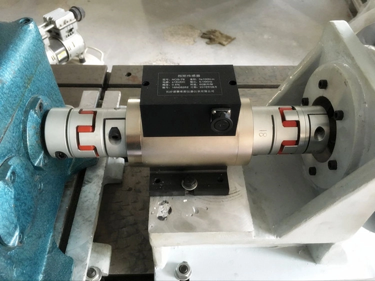
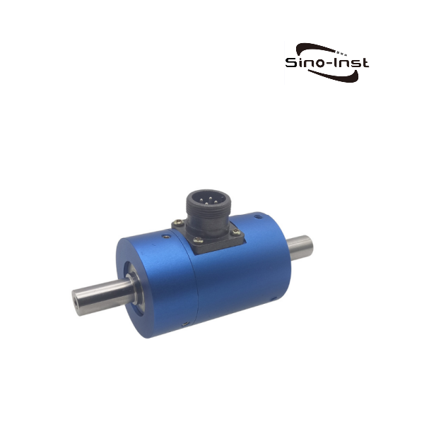
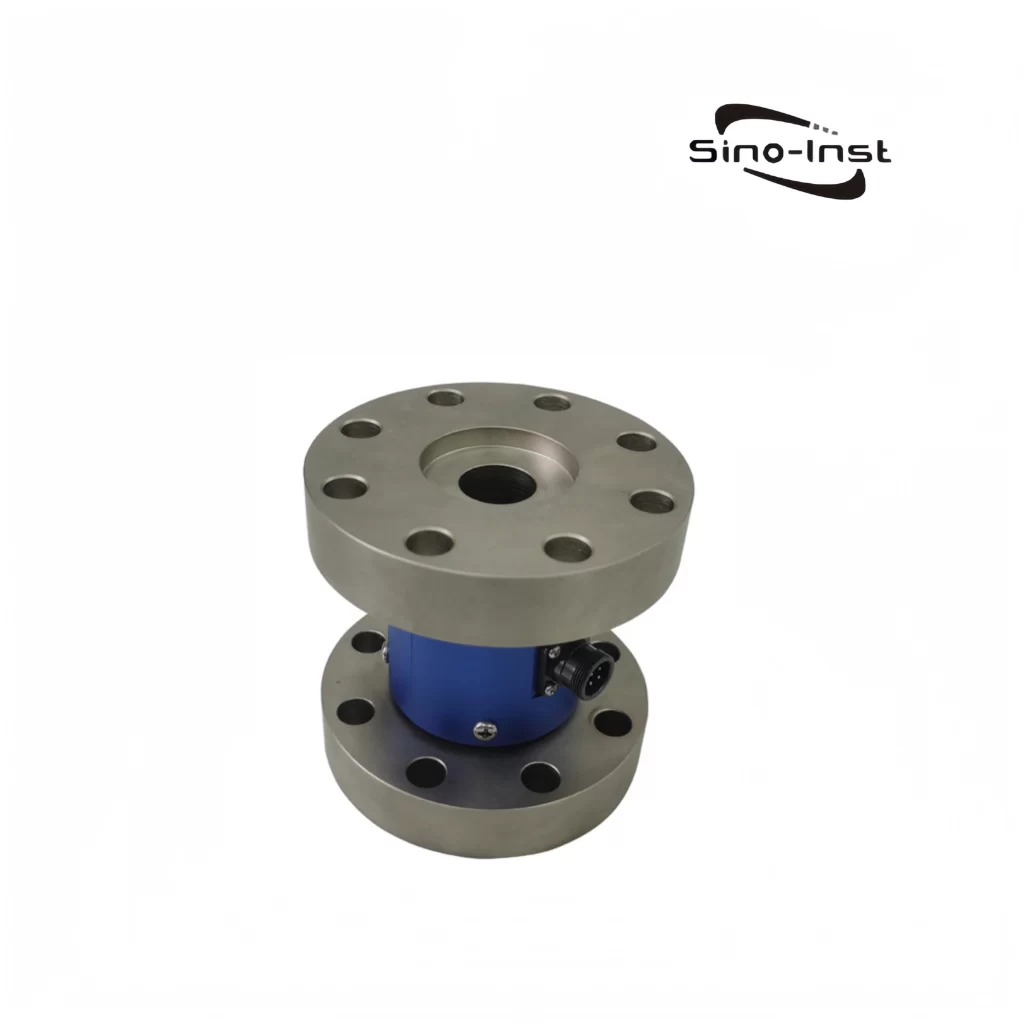
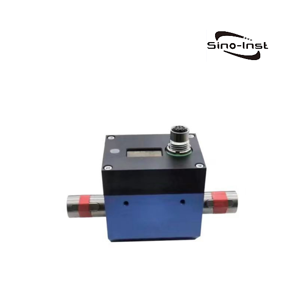
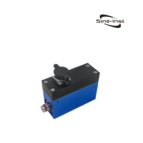
Rotating Torque Sensor: Contact vs. Non-Contact Methods
A dynamic or rotating torque sensor must solve the problem of communicating with a spinning shaft. The sensor body itself is similar to a static sensor—it’s a shaft or flange with strain gauges bonded to it. The innovation lies in how the signal crosses the rotating-to-stationary boundary.
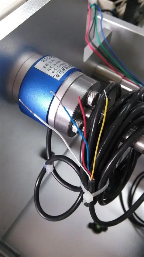
Contact Method: Slip Rings
How it Works: The strain gauge circuit on the rotating shaft is wired to a set of conductive rings that are mounted on and rotate with the shaft. A stationary block holding conductive brushes (often made of a carbon or precious metal composite) presses against these rings. Wires from the stationary data acquisition system are connected to these brushes. As the shaft spins, the brushes maintain continuous electrical contact with the rings, allowing power to flow to the gauges and the measurement signal to flow out.
Pros and Cons: Slip rings are a proven and relatively inexpensive technology. However, they have limitations. The physical contact between the brushes and rings creates friction, which generates heat and introduces a small amount of drag (parasitic torque). The brushes and rings are also subject to wear and require periodic maintenance or replacement. At very high rotational speeds, “brush bounce” can interrupt the signal, limiting their effective RPM range.
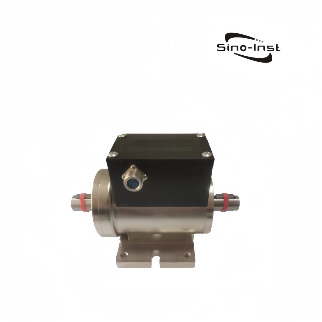
Non-Contact Methods
To overcome the limitations of slip rings, non-contact technologies were developed. These are more complex and expensive but offer superior performance, especially in high-speed or long-term applications.
Rotary Transformers: This method uses inductive coupling. Two transformer coils are used—a primary coil on the stationary housing and a secondary coil on the rotating shaft. An AC signal is fed to the primary coil, which induces a current in the secondary coil, powering the strain gauges. The torque signal from the gauges then modulates this carrier signal, which is transmitted back across the magnetic gap to a pickup on the stationary housing, where it is demodulated and converted into a standard torque reading.
The debate over static torque vs dynamic torque measurement is just the starting point. Considering the specific demands of your application, can lead you to the optimal solution. Let us walk through a five-factor framework for making an informed decision.
This is the most fundamental question and the first one you must answer.
Is there continuous rotation? If the primary goal is to measure torque on a spinning shaft—like a motor output, a gearbox input, or a propeller shaft—you unequivocally need a dynamic torque sensor.
Is the measurement stationary? If you are measuring a force that is resisted without rotation—such as the torque to tighten a bolt, the force to actuate a stationary valve, or the reaction torque from a motor bolted to a test stand—then a static torque sensor (or reaction torque transducer) is the correct and most cost-effective choice.
There can be gray areas. For applications with very slow rotation (less than a few RPM) or oscillatory motion over a limited angle, a static sensor can sometimes be used if it is mounted appropriately (e.g., with flexible couplings). However, one must be cautious about side loads and wear. For any application involving continuous, full rotation, a dynamic sensor is the proper tool.
Accuracy is how close a measurement is to the true value, while resolution is the smallest change in torque the sensor can detect.
High-Precision Applications: Scientific research, aerospace component testing, and calibration labs demand the highest possible accuracy. Non-contact dynamic sensors or high-grade static sensors with excellent thermal stability and linearity are often required. The quality of the signal conditioning electronics is just as important as the sensor itself.
Process Monitoring: For many industrial monitoring tasks, such as checking the load on a mixer, relative changes in torque are more important than absolute accuracy. A mid-range sensor (perhaps a slip-ring type for dynamic applications or a standard industrial reaction transducer) might be perfectly adequate. The goal here is repeatability—ensuring the sensor gives the same reading for the same torque every time.
A torque sensor is not an isolated device; it is part of a larger mechanical system and must survive its operating environment.
Temperature: Temperature fluctuations can cause the sensor’s metal body to expand or contract and can affect the resistance of the strain gauges, leading to measurement drift. High-quality sensors have built-in temperature compensation circuits.
Vibration and Extraneous Loads: A torque sensor is designed to measure twist around its primary axis. Side loads (shear forces) or bending moments can introduce significant errors or even damage the sensor. The mounting arrangement is critical to isolating the sensor from these extraneous loads. In high-vibration environments, the sensor’s mass and rigidity become important factors.
Ingress Protection (IP Rating): Will the sensor be exposed to dust, water, oil, or corrosive chemicals? The sensor’s housing must be rated to withstand these elements. IP ratings (e.g., IP67) provide a standardized way to specify the level of protection against solids and liquids.
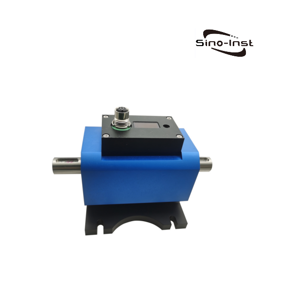
Size and Shape: The physical dimensions—length, diameter, flange size—must be compatible with the available space. In some cases, a custom-designed sensor may be the only option. Flange-to-flange sensors are short and good for tight spaces, while shaft-to-shaft sensors are better for bridging a gap in a drivetrain.
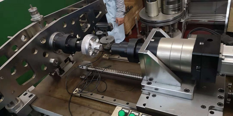
Mounting: How will the sensor be installed? A proper installation is critical for accurate rotating torque measurement and to prevent premature failure. It often involves using flexible couplings on either side of the sensor to accommodate any slight misalignment between the driving and driven shafts. Misalignment is a primary source of bending loads and measurement errors.
Speed (for Dynamic Sensors): The sensor must be rated for the maximum rotational speed of your application. As discussed, slip-ring sensors have lower speed limits than non-contact types. Exceeding the speed rating can lead to catastrophic mechanical failure.
Finally, practical considerations of cost and maintenance come into play.
Initial Cost: Static torque sensors are generally less expensive than dynamic sensors due to their simpler construction. Among dynamic sensors, slip-ring types are the most affordable, while telemetry systems are the most expensive.
Total Cost of Ownership: The initial purchase price is only part of the story. A non-contact dynamic sensor may have a higher upfront cost, but its maintenance-free operation can make it more economical over the long term than a slip-ring sensor that requires periodic brush replacements and the associated downtime.
Reliability: For a critical 24/7 industrial process, reliability is paramount. The proven robustness of a simple reaction torque transducer or the maintenance-free design of a non-contact rotating sensor may be worth the investment to avoid costly production stoppages.
By carefully working through these five factors, you can move beyond the simple static torque vs dynamic torque question and develop a clear specification for the sensor that will deliver the performance, reliability, and value your application demands.
FAQ
What is the main difference between static torque and dynamic torque?
The main difference lies in the motion of the object being measured. Static torque (or reaction torque) is the rotational force on a stationary object, where there is no rotation. Dynamic torque (or rotating torque) is the rotational force measured on a spinning object, like a motor shaft.
Can I use a static torque sensor for a dynamic application?
No, you cannot. A static torque sensor is designed to be fixed and cannot accommodate a continuously rotating shaft. It lacks the necessary bearings and signal transfer mechanism (like slip rings or telemetry) required for a rotating application. Attempting to use it would result in immediate failure of the sensor.
What is a reaction torque transducer?
A reaction torque transducer is another name for a static torque sensor. It is designed to measure reaction forces—the equal and opposite torque that arises when a rotational force is applied to a constrained or fixed object. For example, it can measure the torque a motor exerts on its mounting.
Why are dynamic torque sensors more expensive than static ones?
Dynamic torque sensors are more complex. They need to transmit power and signals to and from a rotating shaft, which requires sophisticated components like slip rings, rotary transformers, or radio telemetry systems. They also incorporate bearings to allow the shaft to spin freely. This complexity in design and manufacturing leads to a higher cost compared to the simpler, solid-state construction of a static sensor.
What is the difference between torque and power?
Torque is a measure of rotational force—the “twist.” Power is the rate at which work is done. In a rotational system, power is calculated by multiplying torque by the rotational speed. You can have a high torque with zero power if there is no rotation (a static condition). To have power, you must have both torque and rotation.
How often should I calibrate my torque sensor?
As a general rule, annual calibration is recommended for most industrial applications. However, the frequency should be adjusted based on usage and criticality. For a sensor used in a critical quality control test that runs 24/7, a 6-month interval might be more appropriate. For a sensor used infrequently in a lab, a 2-year interval could be acceptable. Always follow manufacturer recommendations and any relevant industry standards.
Motor torque testing ensures proper motor operation and the safety of mechanical equipment. Torque sensors have a wide range of applications in motor testing and measurement. Motor torque Motor torque refers to the output torque of the motor, which is the product of the motor output power and the speed. The size of the motor … Read more
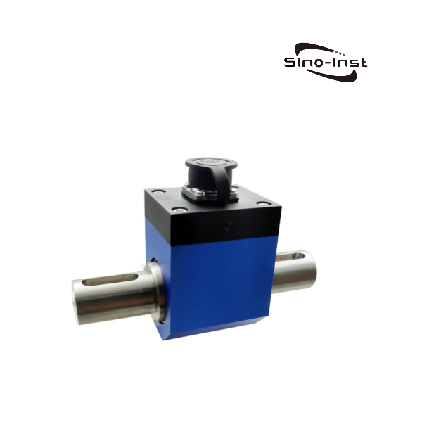
What is a torque sensor? A torque sensor is a device that measures the torque (torsion or rotational force) applied to a rotating shaft of a component or machine. Torque sensors monitor and control the performance and condition of rotating components such as engines, motors, shafts, gears, pulleys, rollers, gears, and generators. They are widely … Read more
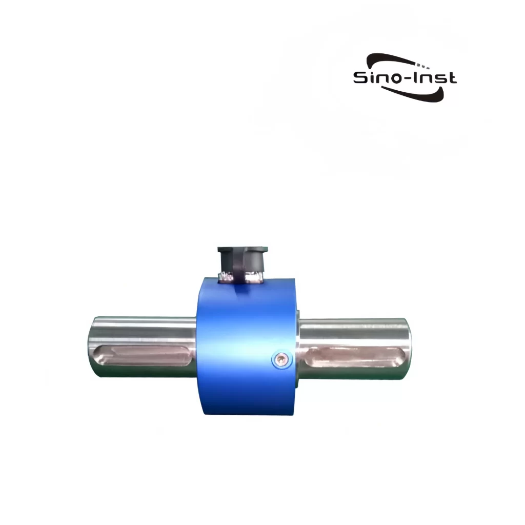
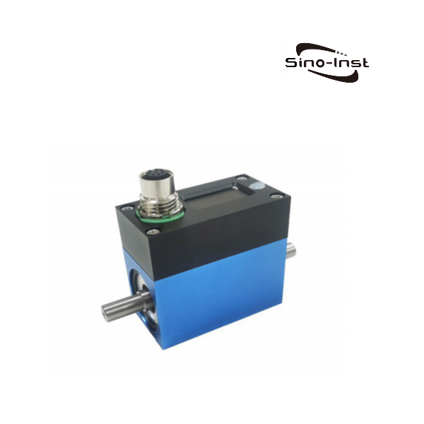
Shaft Torque Sensors are devices that can directly measure the torque of a rotating shaft. This refers to the mounting structure of the torque sensor, such as a flange torque sensor. Compared with flange-mounted torque sensors, shaft-mounted torque sensors take up less space and are relatively inexpensive. Shaft Torque Sensors can be dynamic torque sensors … Read more
Compared with traditional contact torque sensors, Contactless Torque Sensor avoids physical contact. This feature significantly reduces wear and energy loss. Improves the reliability of the measurement system. Contactless Torque Sensor does not mean that the sensor can obtain measurement results without contacting the measured object. Instead, it means that the power supply and signal inside … Read more
In industrial production, torque sensors are widely used on rotating or non-rotating mechanical parts to monitor torque. The industrial applications of torque sensors is mainly to convert torque into electrical signals. Of course, it can also detect speed, power, etc. at the same time. It can be said that torque and speed sensors are indispensable … Read more
A rotary torque sensor is a device that detects the torsional torque on various rotating mechanical parts. It is also called a dynamic torque sensor. It converts the physical change of torque into an accurate electrical signal. It allows us to accurately measure the force applied to the shaft or rotating parts. Sino-Inst provides a … Read more
What is torque? Torque is the rotational force applied to an object, which refers to the moment of rotation of an object around a certain axis. It is a physical quantity that measures the rotational force. It is determined by the product of force and lever arm, and the unit is Newton meter (N m). … Read more
Choosing a static or dynamic torque sensor depends on a deep understanding of the application’s unique mechanical and environmental requirements. At Sino-Inst, we are a professional torque sensor supplier. By carefully considering the nature of the motion, the required accuracy, the operating environment, and the physical constraints, our engineers and technicians can select a torque sensor that not only provides accurate data but also ensures the safety, efficiency, and reliability of your mechanical system for years to come.
If you have a torque measurement requirement, please feel free to contact us.
Zhang Wei, possesses 20 years of experience as an automation instrumentation engineer, specializing in the research, design, installation, commissioning, and maintenance of automation instruments.
Face to various instrument communication protocols (such as Modbus, Profibus, etc.), with solid hardware circuit design and software programming skills (proficient in C language and PLC programming). Has extensive project experience; projects he has led and participated in have all achieved outstanding results, improving product accuracy, reducing costs, and increasing production efficiency.
Possesses excellent communication and coordination skills and a strong team spirit, enabling him to quickly respond to customer needs and provide high-quality automation instrumentation solutions.