-1.jpg)

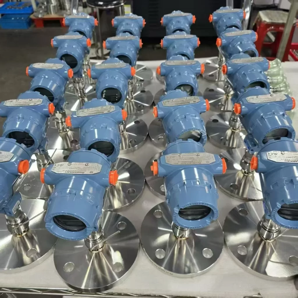
Behind every aspect of industrial process monitoring and control lies an indispensable “invisible hero”—the pressure transmitter. The performance of a pressure transmitter determines safe operation and production efficiency. Chemical plants rely on pressure transmitters to prevent pipeline leaks, and automobile manufacturing depends on hydraulic systems for precise control of robotic arms.
However, the densely packed specifications on pressure transmitter datasheets, such as “range 0-1MPa” and “accuracy ±0.1% FS,” can leave you confused about which to choose. Today, we’ll break down the core specifications of pressure sensors, helping you understand the parameters and avoid getting lost!
Core Parameters: What a Pressure Sensor Can Measure.
1. Measurement Range
The measurement range refers to the pressure range that the sensor can normally measure. For example, “0-10 bar” or “-100 kPa~200 kPa”. The former means it can only measure positive pressure, while the latter can measure both negative pressure (vacuum) and positive pressure simultaneously.
Note: If the actual pressure exceeds the measurement range, it will not only lead to inaccurate measurements but may also damage the sensor’s internal components. For example, applying 2 MPa pressure to a sensor with a measurement range of 0-1 MPa will most likely cause permanent failure.
Tip: When selecting a sensor, it is recommended to allow for a 20% margin in the measurement range. For example, if you actually need to measure pressures of 0-0.8 MPa, choosing a 0-1 MPa range sensor will be more durable.
2. Measurement Range
The measurement range refers to the pressure range that the sensor can normally measure. For example, “0-10 bar” or “-100 kPa~200 kPa”. The former means it can only measure positive pressure, while the latter can measure both negative pressure (vacuum) and positive pressure simultaneously.
Note: If the actual pressure exceeds the measurement range, it will not only lead to inaccurate measurements but may also damage the sensor’s internal components. For example, applying 2 MPa pressure to a sensor with a measurement range of 0-1 MPa will most likely cause permanent failure.
Tip: When selecting a sensor, it is recommended to allow for a 20% margin in the measurement range. For example, if you actually need to measure pressures of 0-0.8 MPa, choosing a 0-1 MPa range sensor will be more durable.
3. Pressure Type
Even with the same “100kPa”, different pressure types have vastly different meanings, making this a common point of confusion:
Gauge Pressure: Pressure value based on atmospheric pressure (approximately 1 bar under normal conditions). Gauge pressure is used for monitoring liquid transport pressure in ordinary chemical pipelines and compressed air systems in industry (e.g., 0.6 bar for compressed air in a workshop is gauge pressure).
Absolute Pressure: Pressure value based on absolute vacuum. Absolute pressure sensors are required for pressure monitoring in vacuum coating equipment and vacuum dryers in semiconductor manufacturing.
Relationship between Gauge and Absolute Pressure Measurements: Absolute Pressure = Gauge Pressure + Atmospheric Pressure
Differential Pressure: Measures the difference between two pressure points. Differential pressure sensors are used for measuring flue gas flow in power plant boilers (calculating flow through differential pressure) and detecting filter clogging in industrial applications (measuring the pressure difference before and after the filter).
4. Units of Pressure
Common units of pressure in practical engineering applications include: bar, kPa, MPa, pa, psi, etc.
1 bar = 0.1 MPa = 100 kPa = 14.5 psi
Bar, MPa, and psi are all units of pressure, representing the pressure exerted per unit area on an object. In physics, pressure refers to the force acting perpendicularly on the surface of an object.
The object receiving the force is its supporting surface, the point of application is on the contact surface, and the direction is perpendicular to the contact surface. The formula is: p = F/S ~ N/m².
One bar is approximately one atmosphere, so when measuring pressure, it is similar to the weight of an object of standard area: 1 bar = 100,000 N/m².
100 kPa is approximately one atmosphere. 100 kilopascals (kPa) = 10 newtons per square centimeter = 0.1 megapascals (MPa) ≈ 14.5 psi = 1 bar.
MPa, one trillion times Pa, is called “Pascal,” hence the abbreviation “megapascal.” Pa represents Newton force per square meter, 1 Pa (Pascal) = 1 N/m² (Newton/square meter), 1 MPa = 1,000,000 Pa.
psi, short for Poundsper square inch, where P stands for pound, S for square, and I for inch. It represents the force in pounds per square inch, 1 bar ≈ 14.5 psi.
Therefore, 1 bar = 100,000 N/m² = 100,000 Pa = 0.1 MPa = 14.5 psi.
Sometimes, we also add the letters g or a after the pressure unit to indicate the type of pressure. For example, 100psig represents a gauge pressure of 100 psi, and 100psia represents an absolute pressure of 100 psi.
5. Output Signal
After measuring pressure, the sensor needs to transmit the signal to the controller (such as a PLC or microcontroller). The output signal is their “communication language,” and common types include:
Analog signals: such as 4-20mA (most commonly used in industrial applications, strong anti-interference capability, suitable for long-distance transmission), 0-5V (suitable for short-distance, low-interference scenarios, such as small production line equipment);
Digital signals: such as RS485 (enables multi-sensor networking, such as centralized management of multiple pressure monitoring points on a production line), HART, I2C/SPI (suitable for small industrial equipment, such as smart instruments).
Choosing the wrong signal type may cause the sensor and controller to “not communicate.” For example, connecting an RS485 sensor to a PLC that requires a 4-20mA signal will render the device completely unusable.
Performance Indicators: Determining the Accuracy of a Pressure Transmitter
If the core parameter is “whether it can measure,” then performance indicators are “how accurately it measures.” These three indicators directly affect measurement accuracy and must be given special attention:
6. Accuracy
Accuracy is the deviation between the sensor’s measured value and the true value. Manuals often specify it as “±0.1% FS,” where “FS” is an abbreviation for “Full Scale.”
For example, a sensor with a range of 0-100 kPa and an accuracy of ±0.1% FS has a maximum error of 100 kPa × 0.1% = ±0.1 kPa. This means that when the actual pressure is 50 kPa, a measured value between 49.9 and 50.1 kPa is normal.
Note: Higher accuracy is not always better. High-precision sensors are more expensive. For example, laboratory calibration requires 0.01% FS accuracy, while 0.5% FS is sufficient for ordinary industrial water pipe pressure monitoring.
7. Zero Drift
Even without applied pressure, the sensor’s output signal may change over time or with temperature; this is called zero drift. For example, a new sensor might output 4mA (standard value) at zero pressure at 25°C, but after one year of use, the zero-pressure output might become 4.05mA. This is an error caused by drift.
Key influencing factors: Temperature (temperature drift is the most common type; the manual will specify “±0.01% FS/°C,” meaning that for every 1°C change in temperature, the zero-point offset does not exceed 0.01% of full scale), and time (long-term drift, usually specified as “±0.02% FS per month”).
Solutions: Regular calibration is recommended, especially in environments with large temperature variations (such as automotive engine compartments or industrial ovens). It is advisable to choose a sensor with “temperature compensation” functionality.
8. Response Time
Response time refers to the time it takes for the sensor to detect a pressure change and for the output signal to stabilize, such as “≤1ms” or “≤100ms.”
Application scenarios determine requirements: measuring instantaneous pressure fluctuations during industrial pump startup requires a fast response (e.g., ≤10ms), while measuring the static pressure of large storage tanks does not have high response time requirements (≤1s is sufficient).
Misconception: Shorter response time is not always better. Faster response sensors are more expensive and may be more susceptible to high-frequency interference. Choosing the right sensor based on specific needs is the most reasonable approach.
Environment and Installation: Determining the Lifespan of a Pressure Transmitter
Besides measurement capability and accuracy, environmental adaptability and installation method directly affect the lifespan of the sensor. These two terms are easily overlooked but crucial:
9. Operating Temperature Range
Transmitters have their own “comfort temperature range,” such as -40℃ to 85℃. Exceeding this range not only reduces accuracy but may also damage components.
Typical Scenarios: Sensors near industrial kilns, where ambient temperatures can reach above 150℃, must be selected with high-temperature resistance; while pressure monitoring of oil pipelines outdoors in northern regions requires sensors resistant to low temperatures (below -40℃).
10. Media Compatibility
The parts of the pressure sensor that come into contact with the measured medium (such as liquids or gases) must be able to resist media corrosion; otherwise, damage to the housing or diaphragm may occur.
Common Misconception: Using ordinary metal sensors to measure industrial acidic wastewater (such as electroplating wastewater) will result in corrosion within a month. The correct approach is to choose corrosion-resistant materials, such as 316L stainless steel (resistant to general acids and alkalis) or PTFE (resistant to strong corrosion).
11. Mounting Type
Common mounting methods include G-thread and NPT thread. Flange mounting is also available upon request.
Note: Excessive force during installation or misalignment of the sensor with the pipe may deform the diaphragm, leading to measurement errors. It is recommended to use a torque wrench and install to the torque specified in the manual, ensuring the mounting surface is flat.

More Pressure Measurement Cases and Solutions
High-Temperature Media Pressure Measurement Case: 900-1200°C
Case-Liquid Oxygen Pressure Measurement
Customized Case: High Temperature and High Pressure Pressure Measurement -100MPa-700℃
How to Choose the Right Oil Pressure Transmitter for Your Application
Pressure Transmitter 4-20mA Guide: Testing and Troubleshooting
DP Transmitters for Filter Differential Pressure Monitoring
Industrial Differential Pressure Sensors | Sino-Inst
What Are Diaphragm Seal Systems in Pressure Measurement? and Types
After reviewing these specifications, you might still be confused – how do you actually choose the right one? Remember these 3 steps to easily solve your problem:
- Define your needs: Clearly define the type of pressure being measured (gauge pressure/absolute pressure/differential pressure), the measurement range, and the output signal (to match the controller);
- Consider the application: Based on the operating temperature and the measured medium, determine the environmental adaptability requirements (e.g., high temperature resistance, corrosion resistance);
- Control the accuracy: Select the appropriate accuracy based on the application (high accuracy for laboratory settings, medium to low accuracy for general industrial applications), avoiding excessive pursuit of higher parameters and wasted costs.
If you are still unsure which pressure transmitter to choose, please feel free to contact our sales engineers. We will provide customized solutions based on your measurement parameters.