Home > Blog > Accurate Flare Gas Measurement Using Thermal Mass Flow Meters
Accurate Flare Gas Measurement Using Thermal Mass Flow Meters
Accurate measurement of flare gas flow presents a significant challenge in industrial process control. This is primarily due to the extreme variability of flare gas flow rates, the unpredictability of gas composition, and harsh operating environments.
Thermal mass flow meters provide a reliable and compliant method for flare gas measurement, enabling industries to meet stringent environmental regulations and optimize process efficiency.
Navigating the Maze: Core Challenges in Flare Gas Measurement
Monitoring flare gas flow is not simply a matter of installing sensors in a pipeline. A flare stack is not a calm, predictable pipeline; it is a chaotic dynamic system serving as a critical safety valve for the plant. Its purpose is to safely burn excess hydrocarbons that cannot be processed or recovered, preventing equipment overpressure. Yet, it is precisely this function that presents measurement challenges.
The Problem of Extreme Flow Rates and Turndown Ratios
During normal plant operation, gas flow may consist of minimal incidental leaks or process emissions, resulting in extremely low, near-stagnant gas velocities. This is commonly referred to as “plant gas” or “purge gas.” Monitoring this low flow is critical, as it indicates the health of plant seals and valves; a gradual increase in flow may signal brewing problems.
Then, an emergency occurs. The unit must shut down rapidly, or relief valves open. Instantly, massive volumes of gas are vented to the flare tower for combustion. Flow rates can increase by a factor of 1000 or more within seconds. The ratio of the maximum flow a flowmeter can accurately measure to its minimum flow is called the “turndown ratio.” Flowmeters monitoring flare gas must possess an extremely high turndown ratio to capture both the subtle whispers of leaks and the violent roar of emergency venting with acceptable accuracy.
Flare Gas Composition Constantly Changes
Flare gas is almost never a single pure substance. It consists of a mixture of multiple gases, and its composition is constantly changing. One moment it may be dominated by methane, the next it could be a large mixture of butane and propane, and the next it might be mixed with inert gases like nitrogen or carbon dioxide. It may also contain corrosive compounds such as hydrogen sulfide (H₂S).
This constant fluctuation in composition poses a significant challenge, particularly for technologies sensitive to the thermal properties of the gas. Therefore, any effective flare gas flow monitoring strategy must account for this chameleon-like nature.
Harsh Environment: Temperature, Pressure, and Contaminants
Flare lines present an extremely demanding environment for precision instruments. The gas itself can reach extremely high temperatures with significant fluctuations. Pressure within the pipeline is typically low, sometimes approaching atmospheric pressure, which complicates certain measurement types.
Furthermore, the gas is often “dirty.” It may carry droplets, particulates (soot), or corrosive substances that can coat, clog, or damage the precision components of flow meters. Instruments with moving parts, like traditional turbine flow meters, quickly fail.
Sensors extending into the flow path are prone to coating with tar-like substances, causing insulation and loss of readings. The instrument must be robust enough to operate reliably for years under these conditions. This demands not only ingenious sensor design but also careful material selection to resist corrosion and thermal stress. Simply functioning within the pipeline presents a significant challenge, drastically narrowing the range of applicable technologies.
The Regulatory Tightrope: Balancing Compliance and Reporting
Beyond technical hurdles lie intricate environmental regulations. Governments and environmental agencies worldwide, such as the U.S. Environmental Protection Agency (EPA) and its Refinery Sector Rule (RSR), are imposing increasingly stringent restrictions on combustion and emissions. These regulations typically mandate precise monitoring of flare gas flow to calculate pollutant emissions, including sulfur dioxide (SO₂) and unburned hydrocarbons (methane).
Therefore, the selected flowmeter is not merely a process control tool but also critical compliance equipment. Its data must withstand scrutiny by auditors, and its reliability must be beyond question. This regulatory pressure is the primary driver prompting industries to seek superior flare gas flow monitoring solutions.
Fix 1: Advanced Ultrasonic Flow Measurement Using Sound Waves
Faced with the harsh challenges of flare environments, engineers turned to a technology that completely avoids direct contact with the gas stream: ultrasonic flow measurement. This technology employs a simple yet ingenious principle, using sound waves to measure flow velocity.
The Principle of Transit-Time Measurement
Two sensors (referred to as transducers) are mounted externally on the flare pipe or inserted into the inner wall. One sensor is positioned upstream of the other. The first transducer sends a high-frequency acoustic pulse toward the second transducer, which travels through the gas to reach it. The system precisely measures the time required for the sound wave to travel. Subsequently, the second transducer sends a return pulse to the first transducer.
When the sound pulse travels with the gas flow (downstream), it is “pushed” by the gas, slightly accelerating its propagation speed. When traveling against the gas flow (upstream), its speed slows, slightly extending the travel time. The flow meter’s electronic components measure this minute propagation time difference.
Since the speed of sound in the gas and the distance between sensors are known, this time difference enables extremely precise calculation of the gas velocity. Using the known gas velocity and the pipe’s cross-sectional area, the system calculates the volumetric flow rate.
It is precisely this operating principle that leads experts to frequently recommend ultrasonic flowmeters for such demanding applications. Ultrasonic flowmeters are inherently robust and durable, capable of withstanding the dynamic conditions commonly encountered in flare lines.
Advantages
Ultrasonic flowmeters offer several key advantages that make them the leading solution for monitoring flare gas flow.
First, their exceptionally wide measurement range—specifically their high turndown ratio—perfectly matches the demands of flare applications. They accurately measure faint purge gas flows and instantly capture peak values from large-scale emergency leaks without delay.
Second, sensors are typically mounted externally (“clamp-on” configuration) or flush with the pipe wall, ensuring no obstructions to gas flow. This eliminates pressure drops within the pipeline and, crucially, prevents probes or moving parts from being damaged or clogged by contaminated, corrosive gases. This non-invasive design significantly reduces maintenance requirements and enhances long-term reliability.
Third, bidirectional measurement capability offers a unique advantage. It detects gas backflow in flare manifolds—a hazard that can occur under certain atmospheric conditions.
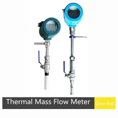
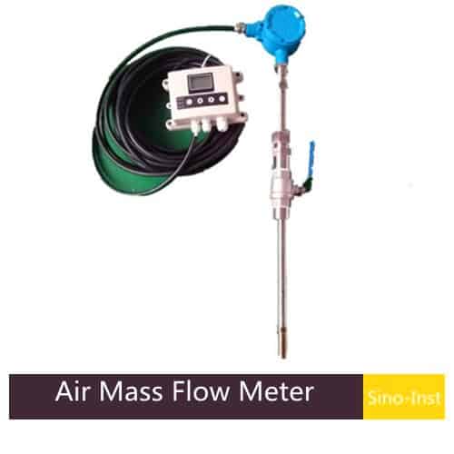
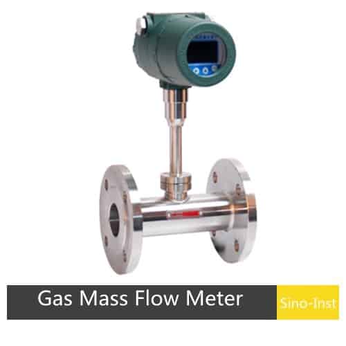
Fix 2: Harnessing Heat with Modern Thermal Mass Flow Meters
While ultrasonic meters masterfully measure velocity, another class of instruments tackles the problem from a different angle, focusing on a property that is, for many, the ultimate goal of measurement: mass. Thermal mass flow meters operate on a beautifully direct and intuitive principle, one you have experienced yourself.
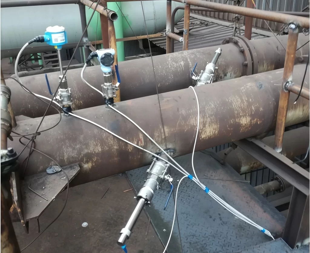
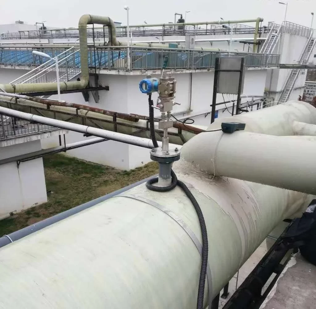
The Fundamentals of Thermal Dispersion
A typical thermal mass flow meter uses two sensors that are inserted into the gas stream, usually housed in a robust metal probe. One of these sensors is a temperature sensor, which simply measures the temperature of the gas. The other sensor is a heated element, which the meter’s electronics maintain at a precise temperature difference above the gas temperature.
As the flare gas flows past the probe, it carries heat away from the heated sensor, just like the breeze cooling your skin. The more gas molecules that flow past, the more heat is carried away. To maintain the constant temperature difference, the meter’s circuit must supply more power to the heated element. This power required to maintain the temperature differential is directly proportional to the mass flow rate of the gas. By measuring this power, the meter provides a direct reading of mass flow (e.g., in kilograms per hour or pounds per minute).
Why Mass Flow is the Goal?
This direct measurement of mass is a profound advantage. Regulations are almost always concerned with the mass of a pollutant emitted, not its volume. Volumetric flow (like cubic feet per minute) is dependent on the gas’s temperature and pressure. A cubic foot of gas at high pressure contains more molecules—and therefore more mass—than a cubic foot of gas at low pressure.
A volumetric meter, like an ultrasonic one, requires separate measurements of pressure and temperature to convert its volume reading into a standardized volume or a mass flow rate. This introduces more instruments to maintain and more potential points of error. A thermal meter, by its very nature, bypasses this. It measures the number of molecules interacting with its sensor, providing a reading that is independent of pressure and temperature variations.
Addressing the Gas Composition Hurdle
However, the thermal principle has an Achilles’ heel: its readings are dependent on the thermal properties of the gas. A gas like hydrogen, which is very effective at transferring heat, will produce a different reading than a gas like nitrogen at the same mass flow rate. This is the flip side of the variable composition challenge.
Early thermal mass flow meters struggled in flare applications for this reason. A meter calibrated for a 100% methane stream would be wildly inaccurate if the gas suddenly became a 50/50 mix of methane and propane. However, modern manufacturers have developed ingenious solutions to this problem.
One common approach is to equip the meter with multiple calibration curves. Based on historical process data, an engineer can program several distinct gas compositions into the meter’s memory—for example, “Normal Operation,” “Startup Mix,” and “Emergency Vent Mix.” The plant’s control system can then tell the meter which calibration to use based on the current process conditions.
Alternatively, modern intelligent thermal mass flow meters also allow users to switch between different gas measurements by modifying the conversion coefficient.
Fix 3: Creating a Hybrid Approach for Unmatched Accuracy
In the world of industrial measurement, the most accurate and reliable solution for monitoring flare gas flows often comes not from choosing one technology over the other, but from combining their strengths in an intelligent, hybrid system. This approach acknowledges the limitations of each technology and uses another to compensate, creating a whole that is far greater than the sum of its parts.
The Power of Synergy: Combining Ultrasonic and Thermal
Let’s reconsider the strengths of our two primary technologies. The ultrasonic meter is the master of dynamics; it handles the vast turndown ratio with ease and is unperturbed by the physical dirtiness of the gas stream. Its weakness is that it measures volume, not mass, and requires an accurate molecular weight value to make the conversion. The thermal mass meter is the master of substance; it measures mass directly, is exceptionally sensitive at the low flow rates critical for leak detection, and provides data in the units regulators demand. Its weakness is its sensitivity to changing gas composition.
What if we could combine them? In some critical applications, a “metering skid” might employ both. The ultrasonic meter acts as the primary workhorse, measuring the flow across the entire operational range. Alongside it, a smaller thermal mass meter might be installed in a bypass line, specifically to measure the very low “sweep gas” flows with high precision.
More powerfully, the data from both can be used to validate one another. If the ultrasonic meter, corrected for gas composition, reports a mass flow that significantly deviates from the direct reading of the thermal meter, it can trigger an alarm, indicating a potential issue with one of the sensors or a dramatic, unexpected shift in gas properties. This redundancy builds a profound level of trust in the measurement.
Integrating Gas Analyzers for Real-Time Correction
The true key to unlocking the highest level of accuracy is to stop guessing the gas composition and start measuring it. This is where a gas analyzer enters the system. This device, often a gas chromatograph (GC) or a simpler multi-spectrum analyzer, is installed to take a continuous or frequent sample of the flare gas.
A GC separates the gas into its individual chemical components (methane, ethane, propane, H₂S, N₂, etc.) and measures the percentage of each. This composition data is then fed electronically, in real-time, to the flow computer or the flow meters themselves.
For the Ultrasonic Meter: The analyzer provides a constantly updated, accurate molecular weight for the gas mixture. The flow computer uses this value to convert the measured volumetric flow into a highly accurate mass flow. The calculation is simple: Mass Flow = Volumetric Flow × Density, and density is directly related to molecular weight.
For the Thermal Mass Meter: The analyzer provides the data needed for the meter’s internal algorithm to calculate the precise thermal properties (thermal conductivity and specific heat) of the current gas mix. This allows the meter to apply a real-time correction factor, eliminating its primary source of error.
This integrated system is the gold standard for monitoring flare gas flows. It transforms the measurement from an approximation based on assumptions into a dynamic, precise, and auditable calculation. It directly addresses the “chameleon gas” problem, ensuring accuracy regardless of how the process conditions change. Accurate measurement is the foundational step toward achieving larger environmental goals, such as net-zero emissions.
System Architecture and Data Management
Constructing such a system requires careful thought about how the components communicate. Typically, the flow meters and the gas analyzer will all be connected to a dedicated flow computer or directly to the plant’s Distributed Control System (DCS). This central brain gathers the raw data—velocity from the ultrasonic, power reading from the thermal, and composition from the analyzer—and performs the necessary calculations.
The importance of the data management aspect cannot be overstated. For regulatory purposes, the system must log all of this data with precise timestamps: the flow rates, the gas compositions, the temperatures, and the pressures. This creates an unassailable record that can be provided to auditors to demonstrate compliance.
Beyond compliance, this rich dataset is an invaluable tool for process optimization. Engineers can analyze trends to identify inefficiencies in the plant that lead to flaring. For example, a recurring pattern of flaring a certain gas might reveal an opportunity to install recovery equipment to capture that gas and use it as fuel, turning a waste stream into a valuable asset. This moves the act of monitoring flare gas flows from a purely environmental cost center to a driver of economic efficiency.
FAQ
Accurate measurement is vital for three main reasons. First, for regulatory compliance, environmental agencies require precise data to calculate and report pollutant emissions, with heavy fines for non-compliance. Second, for economic reasons, flare gas is often a wasted resource. Measuring it accurately is the first step toward potentially recovering it for use as fuel, saving money. Third, for process safety and efficiency, monitoring flare flows can help engineers detect leaks and other inefficiencies within the plant.
The fundamental difference is what they measure. An ultrasonic meter measures the velocity of the gas, from which a volumetric flow rate (e.g., cubic meters per second) is calculated. A thermal mass meter directly measures the mass flow rate (e.g., kilograms per second) by sensing the cooling effect of the gas on a heated probe. Mass flow is often the desired unit for emissions reporting.
While modern meters are very versatile, there is no single “best” meter for every application. The choice depends on specific challenges. Ultrasonic meters are often favored for their extremely high turndown ratio and non-intrusive design, making them ideal for pipes with highly variable flow and dirty gas. Thermal mass meters are excellent for their direct mass flow reading and superior sensitivity at very low flow rates, which is important for leak detection. Often, a hybrid approach offers the best results.
Regulations globally, and particularly in North America and Europe, are continuously becoming stricter. As of 2025, rules like the U.S. EPA’s Refinery Sector Rule (RSR) mandate not just flow measurement but also the continuous monitoring of gas composition to ensure the net heating value of the gas is sufficient for efficient combustion. This pushes facilities toward more sophisticated systems that integrate flow meters with gas analyzers for real-time, compliant data.
Turndown ratio is the ratio of the maximum flow a meter can accurately measure to the minimum flow it can accurately measure. It matters immensely for flare applications because the flow can change dramatically, from a very small, steady flow of “sweep gas” during normal operations to a massive, sudden rush of gas during a plant upset or emergency shutdown. A meter with a high turndown ratio (e.g., 1000:1) is required to accurately capture both of these extremes.
There is no universal answer, as the required frequency depends on the technology, the application’s severity, and regulatory requirements. However, a best practice involves an initial factory calibration, followed by regular in-situ verification checks (e.g., quarterly or semi-annually) using the meter’s built-in diagnostics. A full removal and laboratory recalibration might be required every few years or if a verification check indicates a problem.
Why Natural Gas Flow Measurement is Pivotal? Natural gas is a vital energy source, providing electricity to industries, homes, and businesses worldwide. High-precision natural gas flow measurement is essential for ensuring fair trade, accurate trade measurement, and safe and efficient energy distribution. This article delves into the field of natural gas flow measurement, introducing various … Read more
Gas flow measurement is an essential technology in many industrial processes. For example, in the production of chemical products, accurate measurement of the flow of gases such as oxygen and nitrogen can ensure that the reactants are added to the reactor in the appropriate proportion to obtain high-quality products. Introduction: Why Gas Flow Measurement is … Read more
From extraction to use, natural gas undergoes long pipeline transportation, filtration, storage, and pressure regulation. Monitoring pipeline pressure during these processes is crucial to ensuring proper system operation. Natural gas pressure transmitters are designed to accurately measure a variety of gas pressures. Low and high pressures, gauge pressure, absolute pressure, and differential pressure can all … Read more
Gases are important raw materials in industrial production and laboratories. Such as oxygen, nitrogen, hydrogen, and natural gas. Gases are generally stored and transported in tanks and delivered through pipelines. Monitoring gas pressure during transportation and production helps ensure safe operations and reduce production costs. How do you measure gas pressure? What devices are needed … Read more
Turbine type flow meter is an important velocity flow meter. It has the advantages of easy maintenance, large flow capacity and relatively low price. It has been widely used to measure the flow of liquids and gases. Including petroleum, organic liquids, natural gas, etc. Sino-Inst is one of the manufacturers of Turbine type flow meter, … Read more
In its gaseous form, Propane has numerous applications. Propane is usually used for residential heating, cooking, and powering small appliances. Industrially, propane can be separated from oilfield gas and cracking gas. It can be used as a raw material for the production of ethylene and propylene or as a solvent in the oil refining industry. … Read more
Ascertaining accurate and reliable measurement of gas flow rates is critical for a variety of industrial processes. The ability to measure gas mass flow accurately, rather than simply volumetric flow, provides insights into the true behavior of gases under varying conditions of temperature, pressure, and composition. In this blog post, we will explore the fundamentals … Read more
Liquefied Petroleum Gas (LPG) is an indispensable commodity of domestic and industrial applications. It is increasingly used as an aerosol propellant and a refrigerant, replacing chlorofluorocarbons in an effort to reduce damage to the ozone layer. Choosing the right LPG Gas flow meter is crucial for optimal performance, safety, and efficiency of LPG systems. By … Read more
A rotameter, also known as a variable area flow meter, is widely used to measure the flow rate of various gases, especially in situations where no power supply is available. Whether measuring air, oxygen, nitrogen, carbon dioxide (CO2), or other gases, rotameters provide reliable and accurate results. Of course, rotameters can also be configured as … Read more
When it comes to high-pressure applications, choosing the right flow meter is necessary for checking accuracy, reliability, and safety. High Pressure Flow Meters are perfect when measuring the flow of fluids under high pressures, such as in hydraulic testing. It is also perfect for chemical injection systems, as it withstands pressures up to 6.3MPA~42MPA and … Read more
Monitoring flare gas flow clearly reflects the overall development trend of modern industry: the pursuit of higher efficiency, stronger environmental responsibility, and data-driven decision-making.
Extreme flow dynamics, constantly changing gas chemical composition, and the harsh physical environment of flare pipelines collectively make simple measurement a challenging goal.
However, modern flow measurement technologies are sufficient to meet these challenges. Ultrasonic flow meters, which utilize subtle changes in sound waves to control turbulence, are ingenious; while thermal mass flow meters directly translate the basic principles of heat transfer into regulatory-required mass data. The combination of these two technologies provides a powerful tool for addressing these challenges.
These technologies, especially when combined with the clear data from gas analyzers to form a hybrid system, offer a path to achieving robust, reliable, and proven measurements.
Zhang Wei, possesses 20 years of experience as an automation instrumentation engineer, specializing in the research, design, installation, commissioning, and maintenance of automation instruments.
Face to various instrument communication protocols (such as Modbus, Profibus, etc.), with solid hardware circuit design and software programming skills (proficient in C language and PLC programming). Has extensive project experience; projects he has led and participated in have all achieved outstanding results, improving product accuracy, reducing costs, and increasing production efficiency.
Possesses excellent communication and coordination skills and a strong team spirit, enabling him to quickly respond to customer needs and provide high-quality automation instrumentation solutions.