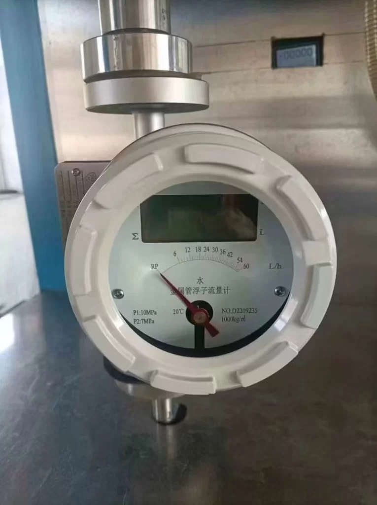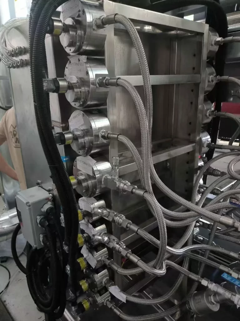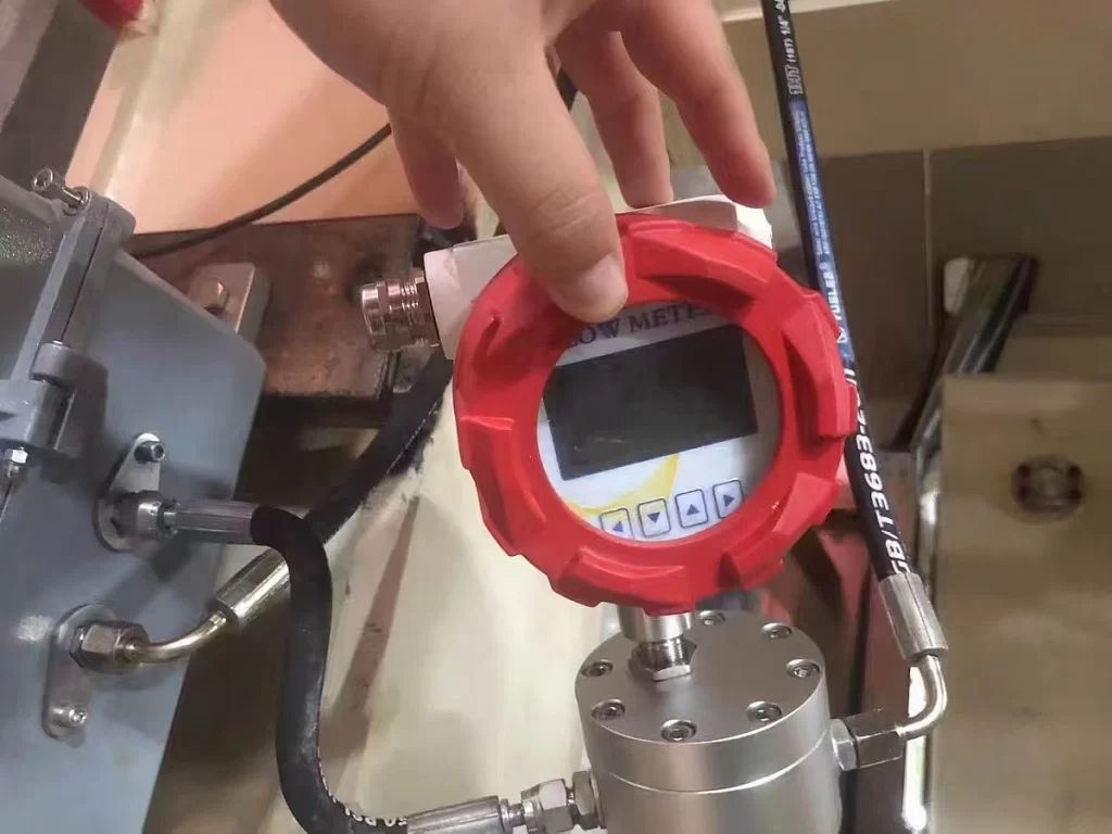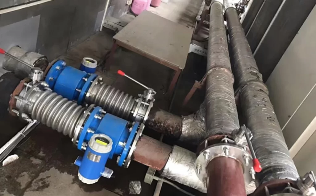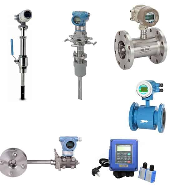
Digital water flow meter is a type of water flow meter that can display instantaneous flow rate and cumulative flow in real time. They are different from traditional mechanical flow meters, water meters, etc. Digital water flow meter needs to be powered on. In addition to being equipped with an LCD display, most of them support signal output. Common pulse, 4-20mA, RS485, HART, etc.
Electromagnetic flowmeter, turbine flowmeter, ultrasonic flowmeter, etc. are all distinctive Digital water flow meters.
Featured Industrial Digital Water Flow Meters
Sino-Inst supplies a variety of industrial digital water flow meters. Suitable for various 1 inch, 3 inch, 6 inch, and even DN3000, DN6000 large-diameter pipes. Customization is supported.
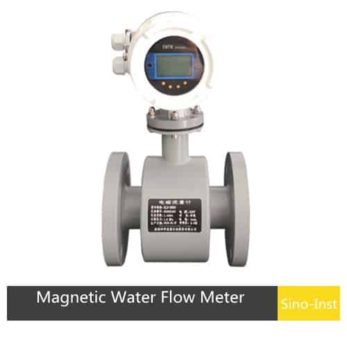
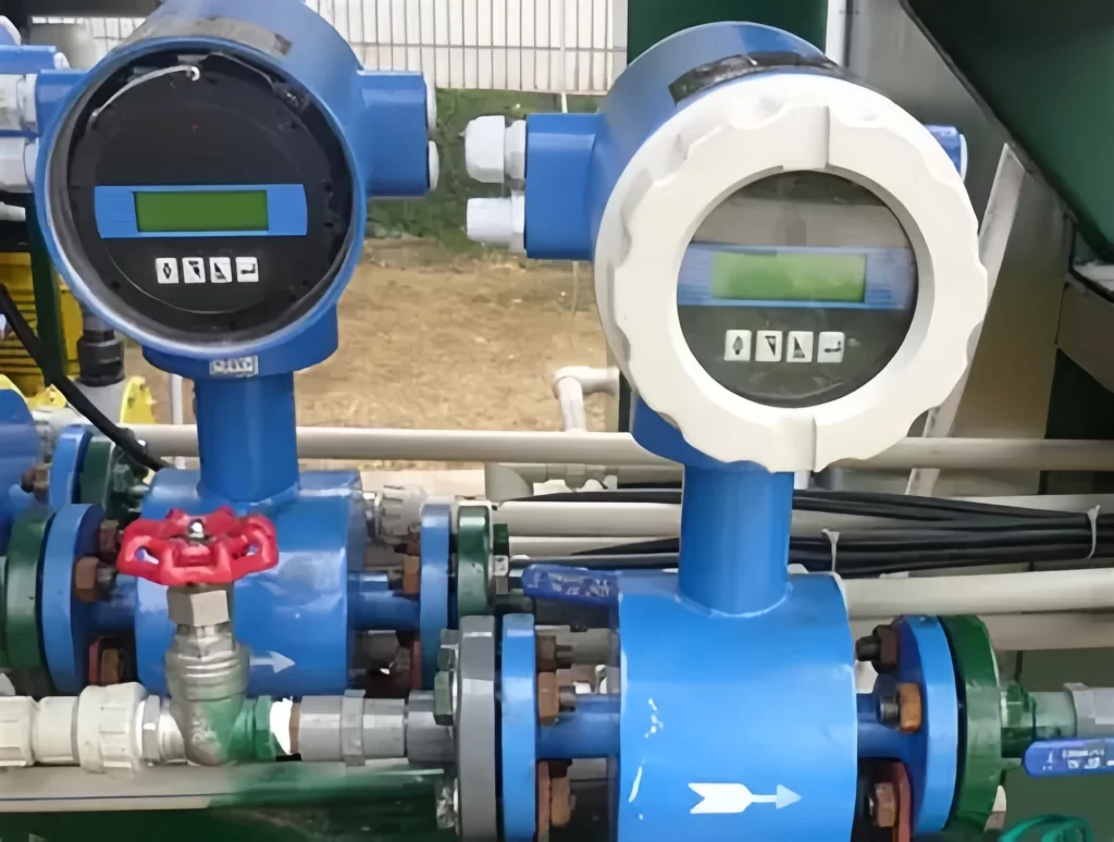
Electromagnetic water flow meter is the preferred flow meter for measuring water flow. Suitable for all conductive liquids.
For example: domestic water, industrial water, raw water, groundwater, urban sewage, industrial wastewater, treated neutral pulp, pulp slurry, etc.
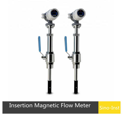
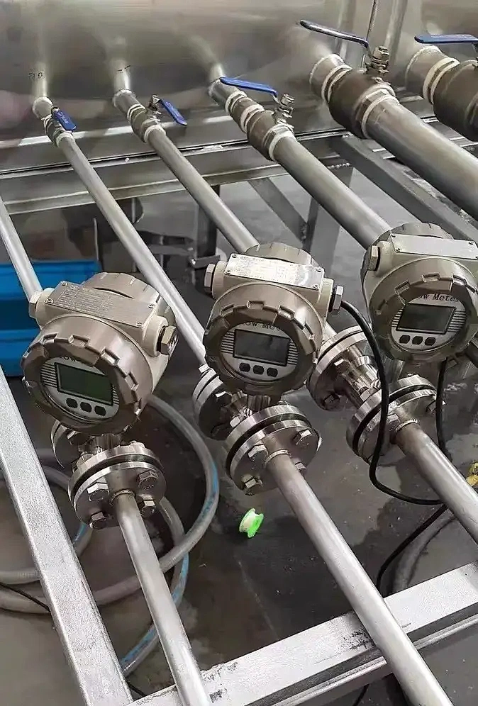
Insertion electromagnetic flowmeter is suitable for measuring the flow rate of conductive liquids in large diameter pipes, DN100~DN3000. Including water, raw sewage, wastewater, clarified water, RAS and WAS. It can be installed in cast iron pipes, cement pipes, PE pipes, etc.
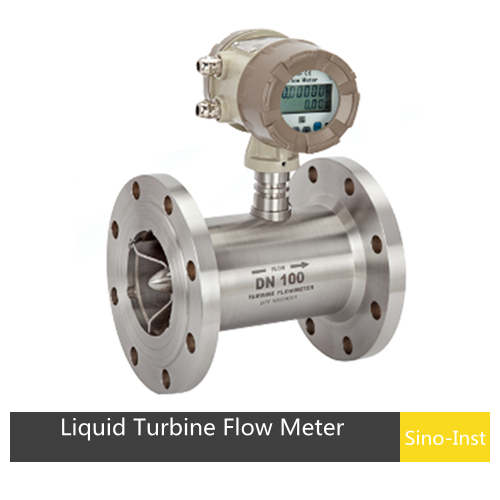
Liquid turbine flowmeter is widely used in liquid flow measurement. It is an important tool for monitoring the flow of clean or low viscosity liquids. Such as water flow, diesel, milk, etc. The measurement accuracy can reach ±0.5% or even higher. After calibration, the error of some models can be controlled within ±0.2%, which is much better than ordinary flowmeters.
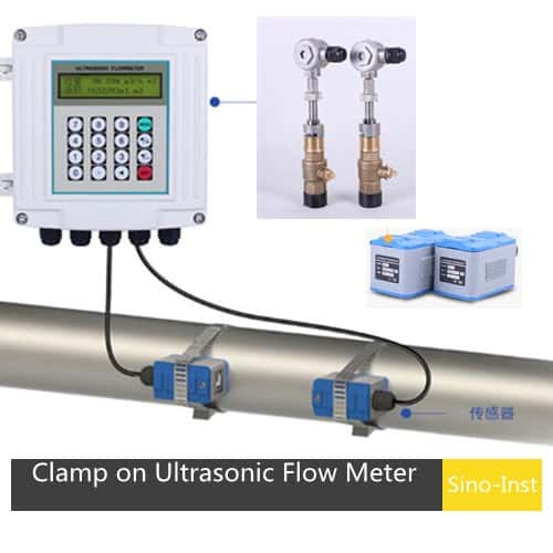
Ultrasonic flowmeters can be used to measure the flow of various clean liquids. The unique non-contact design can avoid changes to the pipeline. And you can choose wall-mounted, handheld, modular and other hosts.
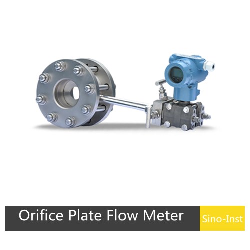
The orifice flowmeter is a high-range differential pressure flowmeter, which is composed of a standard orifice plate and a multi-parameter differential pressure transmitter. It has easy maintenance and stable performance.
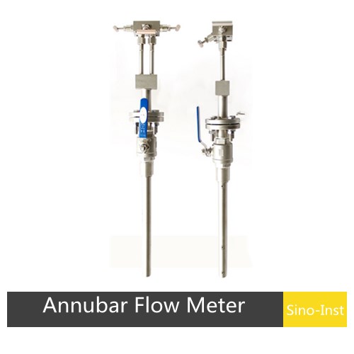
Annubar Flow Meter is a new type of differential pressure flow detection element developed based on the principle of pitot tube velocity measurement. Use with a differential pressure transmitter, it can accurately measure the flow of various liquids, gases and steam (superheated steam and saturated steam) in circular and rectangular pipes.
Types of Industrial Digital Water Flow Meters
Most industrial liquid flow meters can basically be used to measure water. Commonly used ones are:
Read more about: Industrial Water Flow Meter Types and Selection Guide
Water Flow Meter: Digital vs Mechanical
Digital water flow meter is mostly used to monitor water pipe flow in real time. Also known as electronic water meter, it can display instantaneous water flow and cumulative flow. Generally, it needs to be powered by 24VDC, 220VAC, or battery.
Most digital water flow meters have signal output. Pulse, 4-20mA, RS485, HART, etc. It is convenient for users to monitor multiple flow meters at the same time and establish an automated management system.
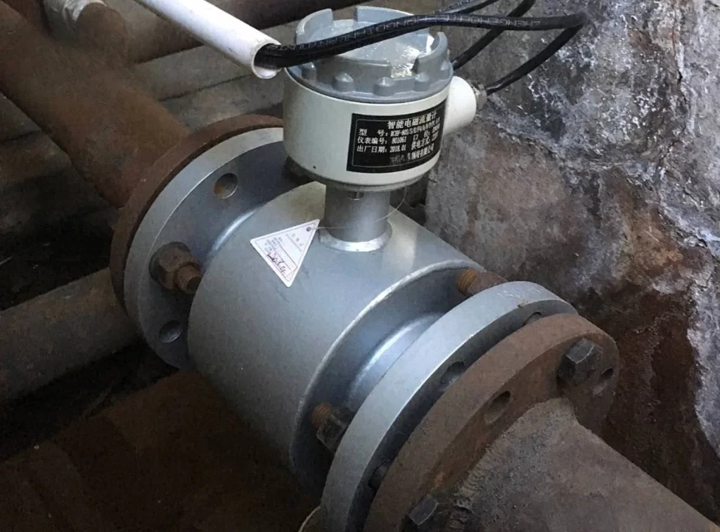
The biggest advantage of mechanical water flow meter is that it does not require power supply. For example, oval gear flow meter and metal rotor flow meter. They all contain moving parts for measuring flow, such as gears and rotors.
Mechanical water flow meter is equipped with pointer display and several rounds of accumulation. In scenarios where there is no power available, mechanical water flow meter is a good choice.
Benefits of Digital Water Flow Meters
Water flow meters have many advantages, the most important of which is the improvement of the efficiency of process systems.
In the industrial field, it is used to monitor and control the supply and discharge of fluids to ensure the stability and safety of the production process.
In the agricultural field, water flow meters are used in irrigation systems to help farmers use water resources rationally and increase crop yields.
In the home, water flow meters can be used to monitor household water consumption, help people save water resources and control water bills.
Water flow meters can also be used in environmental monitoring, energy management, sewage treatment and other fields. Its accuracy and reliability make it an indispensable device in modern industry and life.
How to choose a suitable digital water flow meter?
There are many types of digital water flow meters. To choose the most suitable one, in addition to understanding different types of water flow meters, we also need to analyze the measurement parameters. Refer to the following:
- Pipe diameter
- Flow range
- Temperature
- Pipeline pressure
- Signal output requirements
- Accuracy requirements
- Installation form and size
- Budget
More Flow Measurement Solutions
- Sewage Flow Meters and Effluent Flow Meters for Wastewater
- Dirty Water Flow Meters
- Potable Water Flow Meters In Domestic Water Supply Systems
- The Right Saltwater And Seawater Flow Meter For Your Needs
- Guide for Raw Water And Fresh Water Flow Meters
- Calorimetric Flow Meter: An Economical Solution For Hot Water Flow Measurement
- BTU Meter Optimizes Energy Efficiency of Hot and Cold Water Systems
- Turbine Water Flow Meter: A Versatile And Reliable Choice For Water Flow Measurement
- Pulse Output Flow Meters for Better Water Flow Measurement
Sino-Inst is a professional flow meter manufacturer and supplier. We offer more than 100 flow meter products. About 30% of them are electromagnetic flow meters, and others include turbine, vortex, ultrasonic, and mass flow meters.
Sino-Inst’s flow meters are suitable for industrial applications such as: cooling water, industrial gas, corrosive and brine, chemical processing, mining, wastewater, energy, electronics, laboratory, medical, and many other industries.
Sino-Inst sells through a mature distribution network covering all 50 states and 30 countries around the world. Flow meter products are most popular in Southeast Asia, Europe, and America.
If you need to purchase digital water flow meters, or have related technical questions, please feel free to contact our sales engineers!
-1.jpg)
