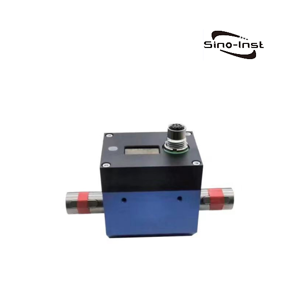
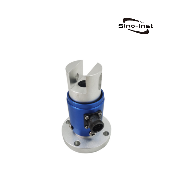
CL1-105 Dynamic Torque Sensor – With Base
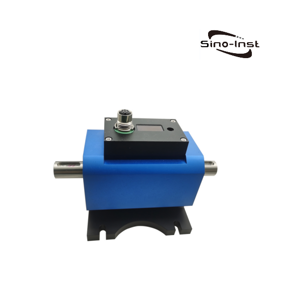
- Non-contact type
- Range 5-5000Nm
- Stainless steel shaft
- Maximum speed 15000RPM
- With speed output
- With panel display of torque/speed/power
CL1-105 Dynamic Torque Sensor Technical Parameters
| Range | 5, 10, 20,30,50, 100-5000 Nm | ||||
| Accuracy | ±0.1, ±0.2%FS | Supply voltage | 12~24VDC | ||
| Zero-point temperature effect | ±0.02%FS | Supply current | Less than 100mA | ||
| Full-scale temperature effect | ±0.02%FS | Electrical connection | 8-Pin | ||
| Compensated temperature range | -10-60℃ | Overload protection | 200%FS | ||
| Operating temperature range | -20~75℃ | Material | Shaft material 17-4PH stainless steel, housing is aluminum | ||
| Torque output | 10±5kHz(5V amplitude), 0-±5VDC, 0-±10VDC, 0-5-10VDC, 4-12-20mA, 0-5V, 0-10V, 4-20mA, RS485, RS232, CAN, etc. | ||||
| Options | |||||
| Rotation speed measurement | 60 pulses/circle 4-20mA, 0-5VDC, 0-10VDC, RS485, RS232, CAN, etc. | ||||
Dimensions

| Model | Cap(Nm) | A | B | C | D | E | G | OH | h | J | K | M | H1 | H2 | H3 | H4 | Key (b*h*l*n) |
| CL1-105A | 5-100 | 175 | 111 | 3.5 | 2 | 30 | 80 | 18 | 14.5 | 6.5 | 83 | 100 | 10 | 53.5 | 88.5 | 15 | 6*6*22*1 |
| CL1-105B | 200-500 | 198 | 114 | 3 | 7 | 35 | 84 | 28 | 24 | 6.5 | 97 | 114 | 10 | 61 | 103.5 | 15 | 8*7*30*1 |
| CL1-105C | 1K-2K | 288 | 134 | 5 | 7 | 70 | 94 | 45 | 34 | 9 | 142 | 175 | 18 | 89 | 151.5 | 10 | 14*9*60*2 |
| CL1-105D | 3K-5K | 355 | 141 | 4 | 7 | 100 | 100 | 75 | 60 | 11 | 181 | 220 | 20 | 110.5 | 190.5 | 10 | 20*12*93*2 |
Torque sensor installation
There are two main ways to install a torque sensor: base support installation and suspension installation. The following will explain these two installation methods and precautions in detail:
Base support installation
Features: Base support installation refers to the installation of the torque sensor on a foundation with a supporting structure, which is usually called a base or support frame. This installation method ensures that the sensor will not be suspended in the drive system, providing better stability.
Installation steps:
- Choose a suitable foundation: Make sure that the power equipment, sensor and load equipment are all installed on a stable foundation to reduce the impact of vibration on the measurement.
- Consider parallelism and angular errors: The parallelism and angular errors at both ends of the sensor need to be considered when installing the base support. This usually requires full coupling (i.e. rigid coupling) or double flexible coupling at both ends of the sensor to ensure good coaxiality.
- Installing couplers: Install couplers (such as elastic pin couplings or rigid couplings) at both ends of the sensor. To ensure good coaxiality between the axis of the power equipment and the load equipment and the axis of the sensor.
- Adjust coaxially: Adjust the distance between the axis of the power equipment and the load equipment relative to the reference plane. Make their axis coaxially less than the specified value (such as Φ0.05mm or less).
- Fixed installation: Finally, fix the power equipment and the load equipment on the reference plane. And make sure that the position of the torque sensor also meets the requirements.

Suspension installation
Features: Suspension installation means that the torque sensor has no additional support, but is directly installed between the two half-couplings of the drive system.
Installation steps:

- Choose a suitable foundation: Similarly, make sure that the power equipment and the load equipment are installed on a stable foundation.
- Install the coupler: In this installation method, usually only the adjustment of parallel misalignment needs to be considered because the angular displacement can be compensated by the suspended sensor. Therefore, only the coupler needs to be installed at both ends of the sensor.
- Adjust parallelism: Adjust the parallelism of the axis of the power equipment and the load equipment to meet the specified requirements.
- Fixed installation: After fixing the power equipment and the load equipment, place the torque sensor between the two half-couplings.
General Precautions
- Installation direction: The torque sensor can be installed horizontally or vertically.
- Reduce vibration: Make sure that all equipment is installed on a stable foundation to reduce unnecessary vibration.
- Coaxiality requirements: The axis coaxiality of the power equipment, sensor and load equipment should meet the specified standards, usually less than Φ0.05mm.
- Coupler selection: Choose the right coupler for your application, such as a flexible pin coupling or a rigid coupling.
- Maintenance and calibration: Perform regular maintenance and calibration to ensure measurement accuracy and long-term stability of the sensor.
The above is a general installation guide for torque sensors. For specific installation steps and details, refer to our installation instructions.
More Torque Sensors and Solutions
Dynamic Torque Sensor is an important accessory for many mechanical equipment. Sino-Inst torque sensor has high accuracy, fast frequency response and is also relatively reliable. It can help enterprises improve production efficiency and product quality, reduce costs and risks, and realize intelligent production.
If you need to purchase dynamic torque sensor or have related technical questions, please feel free to contact us.

Zhang Wei, possesses 20 years of experience as an automation instrumentation engineer, specializing in the research, design, installation, commissioning, and maintenance of automation instruments.
Face to various instrument communication protocols (such as Modbus, Profibus, etc.), with solid hardware circuit design and software programming skills (proficient in C language and PLC programming). Has extensive project experience; projects he has led and participated in have all achieved outstanding results, improving product accuracy, reducing costs, and increasing production efficiency.
Possesses excellent communication and coordination skills and a strong team spirit, enabling him to quickly respond to customer needs and provide high-quality automation instrumentation solutions.
CL1-105 Dynamic Torque Sensor - With Base - Sino-Inst
Dynamic Torque Sensor is an important accessory for many mechanical equipment. Sino-Inst torque sensor has high accuracy, fast frequency response and is also relatively reliable. It can help enterprises improve production efficiency and product quality, reduce costs and risks, and realize intelligent production.
Product SKU: CL1-105 Dynamic Torque Sensor - With Base
Product Brand: Sino-Inst
Product Currency: USD
Price Valid Until: 2029-09-09
Product In-Stock: InStock
5