The wedge flow meter is a new type of flow measurement device for viscous and abrasive fluids.
It features a special structure with no stagnant zones and no clogging. It is robust and has a long service life. It can be used to measure liquids, gases, and steam. It is particularly suitable for measuring the flow rate of fluids with low flow velocities (Reynolds number as low as 300), high viscosity, and containing dust or solid particles. Examples include crude oil, fuel oil, oil slurry, asphalt oil, coal tar, wastewater, iron ore slurry, carbon black solution, two-phase fluids, and fluids containing solid particles.
A wedge flow meter is a type of differential pressure flow meter that measures pipe flow by generating a differential pressure using a wedge-shaped throttling element.
The wedge flow meter is essentially a robust and durable differential pressure (DP) flow meter.
Its principle is simple:
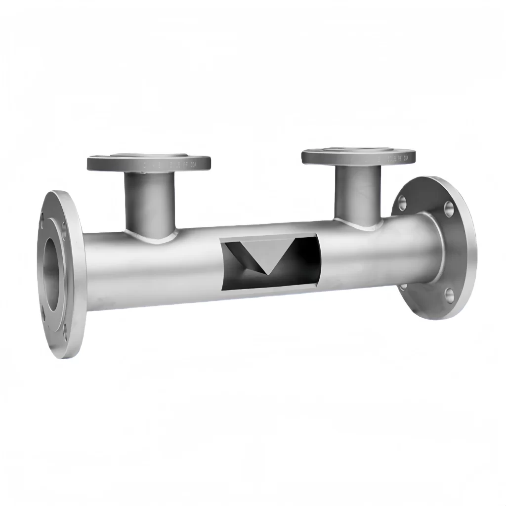
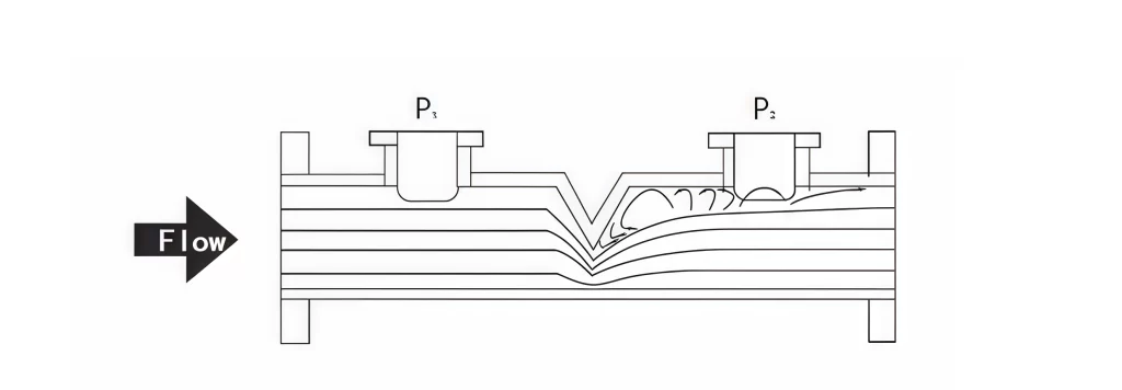
A wedge flow meter utilizes a “V”-shaped wedge restriction element placed in the pipe section. When the fluid flows through the wedge restriction, a differential pressure is created across the restriction. For any fluid, the flow rate is proportional to the square root of the differential pressure over a wide range of flow rates. Unlike complex electronic flow meters, the wedge flow meter is based on fundamental physical principles, making it extremely reliable even in harsh industrial environments.
This operation relies on the basic principles of fluid mechanics: the continuity equation and Bernoulli’s energy equation. We use a high-precision transmitter to measure this differential pressure (DP). The square root of the resulting differential pressure is proportional to the flow rate, allowing for accurate calculation of volumetric or mass flow rate.
The key to this technology lies in the wedge-shaped element. Unlike concentric orifices such as orifice plates, we use V-shaped wedges welded to the pipe. This wedge acts as a dam, restricting fluid flow and creating the necessary pressure drop.
Why use a V-shape?
Non-clogging: The segmented opening allows solids and slurries to pass beneath the restriction without accumulating.
Durability: The wedge element is robust enough to withstand the impact of abrasive fluids that would damage other primary elements.
Viscosity handling: Maintains linearity even with high-viscosity fluids.
The biggest advantage of wedge flow meters is their ability to handle viscous, sticky, or particle-laden fluids.
Clog-resistant design: The angled shape ensures that suspended solids, sludge, or tar do not accumulate on the meter.
Stable readings: Even with heavy crude oil or wastewater, the instrument maintains accuracy without frequent cleaning.
Wedge flow meters are robust and durable. Their wedge structure is sturdy and lacks sharp edges that are susceptible to rapid wear. This ensures a long service life, even in highly corrosive process fluids.
The wedge design of this flow meter allows it to maintain a stable flow coefficient even at Reynolds numbers as low as 500. This means accurate data can be obtained even at slow flow rates.
Due to the symmetrical nature of the wedge restrictor, these flow meters offer excellent bidirectional flow measurement capabilities.
Self-cleaning function prevents clogging. The unique positioning of the V-shaped throttling device allows suspended solids, fibers, and crystals to pass freely beneath the wedge restrictor. There are no “dead zones” or stagnant areas, so debris does not accumulate.
Top Features
The throttling element is a V-shaped wedge, which changes the throttling method. It eliminates stagnant flow zones, facilitating the smooth passage of granular fluids and suspended solids through the wedge-shaped throttling element.
The fluid accelerates as it approaches the wedge, and the high-speed fluid has a cleaning effect on the wedge and the inner wall of the pipe, preventing adhesion and sedimentation on the throttling element.
The sensor maintains a square relationship between flow rate and differential pressure even at extremely low pipe Reynolds numbers (Re=500), which is beneficial for measuring low flow rates and high-viscosity fluids. The upper limit of the Reynolds number can reach over 10⁶, thus providing a wide range of applications.
The symmetrical structure of the wedge sensor ensures that the same differential pressure signal is generated regardless of whether the fluid flows in the forward or reverse direction. Using two differential pressure transmitters, bidirectional flow measurement in both forward and reverse directions is possible.
The wedge-shaped throttling element of the wedge sensor has a rectifying and redistributing effect on the fluid, so a shorter straight pipe section can still ensure measurement accuracy.
The pressure loss is low, only 1/2 to 1/3 of that of an orifice plate.
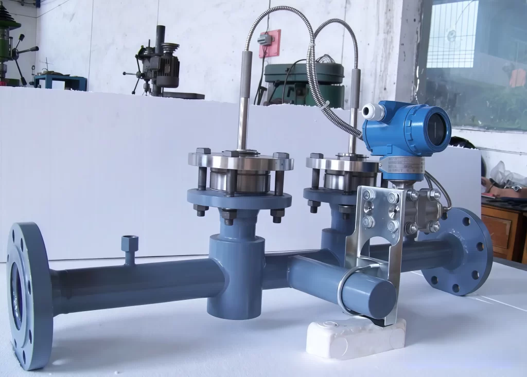
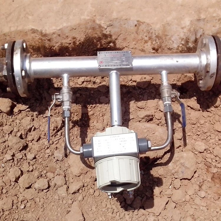
The integrated structure design combines temperature, pressure, and differential pressure display into one unit, simultaneously displaying them on an LCD screen. This eliminates the need for pressure-sensing pipelines and the blockages and leaks caused by them, making installation convenient.
The wedge sensor can be configured with any transmitter specified by the user, outputting 4-20mA, differential pressure, or flow rate signals.
It offers high measurement accuracy (±0.5%), good repeatability (±0.1%), and a wide range (10:1).
Each instrument is calibrated on a standard device before leaving the factory, ensuring measurement accuracy.
Technical Parameters
Nominal Diameter (mm)
DN10–DN600
Accuracy
Accuracy after calibration: 1%, 0.5%; without calibration: 3%
Medium Temperature
Maximum temperature: 400℃
Material
Rectifying element material: 304, 316, 316L, HC, etc.
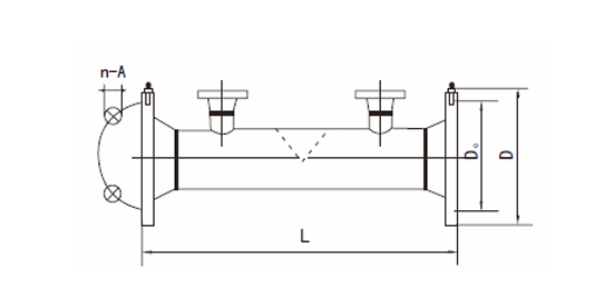
When measuring fluid temperature, the temperature transmitter is installed 5D downstream of the sensor; when measuring fluid pressure, the pressure transmitter is installed 10D upstream of the sensor.
Depending on the nature of the measured medium and the relative position of the wedge-type sensor and the differential pressure transmitter (or intelligent differential pressure flow totalizer), the differential pressure signal pipeline installation should comply with on-site pipeline installation process requirements.
For wedge-type flow meters installed on horizontal or inclined process pipelines, the drain hole should be located directly above the pipe for liquid media, and directly below the process pipe for gases and steam.
Key Industrial Applications for Wedge Flow Meters
Our wedge flow meter is engineered specifically for the “difficult” fluids that cause standard meters to fail. We focus on harsh process flow measurement where high viscosity, low Reynolds numbers, and suspended solids are the norm.
Slurries and Sludge in Mining and Wastewater
Standard meters clog when facing fluids with suspended particles or fibers. Our slurry flow meter design utilizes a V-shaped throttle that allows solids to pass freely without accumulation. This makes it ideal for wastewater treatment plants handling raw sewage and mining operations moving ore slurries.
Heavy Oils, Asphalt, and Bitumen
For the oil and gas sector, viscous fluid flow measurement is a critical challenge. We handle fluids with viscosities up to 500 mPa.s. This includes heavy oil, tar, asphalt, and bitumen. The wedge structure maintains accuracy even when the fluid is thick and moving slowly (low Reynolds numbers).
Abrasive Chemicals and Pulp Processing
In chemical and paper industries, equipment wear is a major concern. As an abrasive media flow meter, our device withstands the erosion caused by pulp suspensions and crystallizing liquids. The robust structure ensures long-term reliability without the need for frequent maintenance or cleaning.
Dirty Gases and Solids-Laden Liquids
Whether it is coal-water slurry or dirty gases containing particulate matter, our solids-containing fluid meter delivers stable differential pressure readings. The self-cleaning nature of the wedge element prevents the “dead zones” where debris typically builds up, ensuring consistent performance in dirty gas applications.
What Is a Differential Pressure Flow Meter? A differential pressure flow meter is a device that measures flow rate by measuring the pressure difference. The differential pressure transmitter is the key component in differential pressure flow measurement. Using a differential pressure transmitter, the pressure difference before and after a pipe throttling device can be measured. … Read more
Explore flow measurement devices. Compare DP, magnetic, and other flow meters to select the right industrial sensor for your application. Flow measurement devices are used to measure the flow rate of fluids in pipes or open channels. Common types include electromagnetic flow meters, ultrasonic flow meters, and turbine flow meters. In my experience working with … Read more
Differential pressure flow measurement represents a foundational and widely applied methodology in industrial process control. This technology operates on the principle, articulated by Bernoulli’s equation, that a fluid’s velocity is inversely related to its pressure. By introducing a precisely engineered constriction, known as a primary flow element, into a pipe, a localized pressure drop is … Read more
The transit-time ultrasonic flowmeter is a competitive flow measurement method in the world today. And its measurement line accuracy is higher than 1.0%. Due to the diversity of the industrial site, especially the environment around the pipeline, how to install and debug the ultrasonic flowmeter according to the specific environment has become an important subject … Read more
Accurate flow measurement is crucial for process control. Before purchasing a flow meter, you should consider the installation requirements. The meter’s installation location and the length of upstream and downstream straight pipe runs directly affect the accuracy of the measurement results. Are Straight Pipe Runs Necessary for Flow Meters? In fact, the answer is not … Read more
An oval gear flowmeter, also known as a displacement flowmeter, is a type of positive displacement flowmeter and offers the highest accuracy among flow instruments. It is particularly suitable for measuring the flow of highly viscous liquids such as heavy oil, asphalt, paint, diesel, and bunker fuel. An oval gear flowmeter uses a mechanical measuring … Read more
In its gaseous form, Propane has numerous applications. Propane is usually used for residential heating, cooking, and powering small appliances. Industrially, propane can be separated from oilfield gas and cracking gas. It can be used as a raw material for the production of ethylene and propylene or as a solvent in the oil refining industry. … Read more
An Annubar is a type of insertion flow meter founded on the averaging pitot principle. That’s why Annubar flow meter are sometimes referred to as Averaging pitots. It is used to measure the flow of liquid, gas or steam that flows through a pipe. The name annubar has become synonymous with averaging pitot tubes despite … Read more
Order Guide
Wedge-type flow meters are often customized based on the user’s actual measurement parameters. Therefore, you need to confirm the following parameters in advance:
Measured Medium: Air, Liquid, or Steam
Medium Temperature (°C)
Medium Viscosity (mPa.s)
Medium Pressure (MPa)
Unit Selection: L/h, m³/h, Nm³/h, kg/h, t/h
Minimum-Normal-Maximum Flow Rate Range:
Installation and Environmental Conditions:
Process Pipe Outer Diameter:
Process Pipe Inner Diameter:
Pipe Material:
Installation Orientation: Vertical, Horizontal, or Other
For viscous sludges, abrasive slurries, or thick oils that can clog standard flow meters, wedge flow meters are an economical and reliable option that will not be blocked by high-viscosity media.
Sino-Inst manufactures and supplies wedge flow meters, supporting customization for high temperature, high pressure, and high viscosity applications. Please feel free to contact us!
Zhang Wei, possesses 20 years of experience as an automation instrumentation engineer, specializing in the research, design, installation, commissioning, and maintenance of automation instruments.
Face to various instrument communication protocols (such as Modbus, Profibus, etc.), with solid hardware circuit design and software programming skills (proficient in C language and PLC programming). Has extensive project experience; projects he has led and participated in have all achieved outstanding results, improving product accuracy, reducing costs, and increasing production efficiency.
Possesses excellent communication and coordination skills and a strong team spirit, enabling him to quickly respond to customer needs and provide high-quality automation instrumentation solutions.
Wedge Flow Meter for Viscous and Abrasive Fluids - Sino-Inst
The wedge flow meter is a new type of flow measurement device for viscous and abrasive fluids.
Product SKU:
Wedge Flow Meter for Viscous and Abrasive Fluids