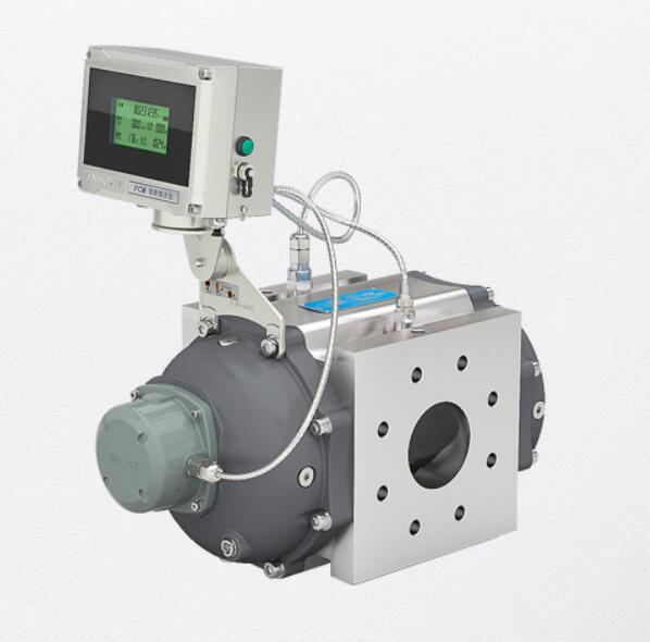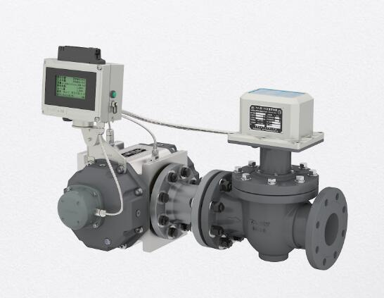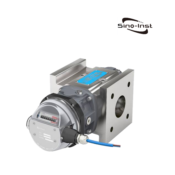
TYL series roots gas meter is a volumetric gas meter with high precision, high reliability, wide range and low initial flow rate. It can directly measure the working volume of gas. It can be equipped with a mechanical counter or a photoelectric direct-reading counter. Various volume correctors can also be optionally equipped to achieve gas temperature and pressure measurement and volume conversion.
This product has various structural forms and functional configurations. Such as the Internet of Things, anti-theft gas monitoring, prepayment and other functions. It has been widely used in fields such as city gas and industrial gas flow measurement and detection.
Features
- Long service life:
- The rotor is precision machined and balanced, high-strength surface treatment, wear-free rotation, non-contact sealing, self-cleaning function and good bearing lubrication. These exquisite designs and processes ensure that the flow meter works normally for a long time.
- Range width:
- The range of flow meters of different specifications is 25:1 ~ 260:1.
- High precision and high reliability:
- The rotor is treated with high-precision bearings and dynamic balancing technology to ensure long-term accurate and stable operation of the product.
- Starting flow is extremely low:
- The starting flow rate of flow meters of different specifications is 0.03 m³/h ~ 1.20 m³/h.
- Small pressure loss:
- The pressure loss of flow meters of different specifications is 0.08 kPa ~ 0.70 kPa.
- Good versatility:
- Common accessories are available for all specifications of flow meter body components.
- Good interchangeability:
- Accessories can be interchanged with meter body components of the same specifications.
- Multiple structural forms:
- Different types of volume correctors or flow compensation controllers can be selected according to functional needs.
TYL Series Roots Gas Meter Technical Parameters
1. Flowmeter model specifications, basic parameters and performance indicators
| Model | Diameter (mm/inch) | Nominal pressure/maximum working pressure (MPa) | range | Flow range (m³/h) | Starting flow rate (m³/h) | Stop flow (m³/h) | Pressure loss at q (kPa) | Low frequency pulse equivalent (m³) |
| TYL-G6 | 20(¾”) | 1.6 2.0 | 25:1 | 0.4~10 | 0.03 | 0.02 | 0.13 | 0.01 |
| TYL-G10 | 25(1″) | 40:1 | 0.4~16 | 0.03 | 0.02 | 0.08 | 0.1 | |
| TYL-G16 | 32(1¼”) | 50:1 | 0.5 ~ 25 | 0.08 | 0.06 | 0.14 | ||
| 40(1½”) | 50:1 | 0.5~25 | 0.08 | 0.06 | 0.12 | |||
| 50(2″) | 50:1 | 0.5 ~ 25 | 0.08 | 0.06 | 0.15 | |||
| TYL-G25 | 40(1½”) | 80:1 | 0.5~40 | 0.06 | 0.05 | 0.15 | ||
| 50(2″) | 80:1 | 0.5~40 | 0.06 | 0.05 | 0.13 | |||
| TYL-G40 | 40(1½”) | 130:1 | 0.5 ~65 | 0.06 | 0.04 | 0.35 | ||
| 50(2″) | 130:1 | 0.5 ~65 | 0.06 | 0.04 | 0.24 | |||
| TYL-G65 | 50(2″) | 200:1 | 0.5~100 | 0.06 | 0.05 | 0.42 | ||
| TYL-G100 | 80(3″) | 250:1 | 0.65~160 | 0.04 | 0.03 | 0.42 | 1.0 | |
| TYL-G160-3″ | 80(3″) | 160:1 | 1.6~250 | 0.15 | 0.10 | 0.52 | ||
| TYL-G160-4″ | 100(4″) | 160:1 | 1.6~250 | 0.15 | 0.10 | 0.39 | ||
| TYL-G250 | 100(4″) | 200:1 | 2.0~400 | 0.10 | 0.06 | 0.51 | ||
| TYL-G250-6″ | 150(6″) | 60:1 | 6.5~400 | 0.70 | 0.50 | 0.31 | ||
| TYL-G400-4″ | 100(4″) | 260:1 | 2.5 ~650 | 0.30 | 0.20 | 0.70 | ||
| TYL-G400-6″ | 150(6″) | 100:1 | 6.5 ~650 | 0.70 | 0.50 | 0.43 | ||
| TYL-G650 | 150(6″) | 160:1 | 6.5~1000 | 0.80 | 0.60 | 0.47 | ||
| TYL-G1000 | 200(8″) | 160:1 | 10~1600 | 1.20 | 0.90 | 0.65 | ||
| Pressure loss refers to the value measured with dry air (density approximately 1.2kg/m³) under normal pressure. | ||||||||
2. Flowmeter accuracy level
Within the range of the flow meter, its accuracy level and maximum indication error:
Level 1.0: ±1.0% (Qt ≤Q≤Qmax), ±2.0% (Qmin ≤Q<Qt);
Qt is the boundary flow value. When the range is <50:1, Qt=10%Qmax;
When the range degree ≥ 50:1, Qt=5%Qmax.
3. Environmental conditions
- Ambient temperature: -30℃~+60℃, when equipped with a volume corrector, it is determined by the corrector;
- Relative humidity: 5% ~ 95%;
- Atmospheric pressure: 70kPa ~ 106kPa.
- 4 Media conditions
- Medium temperature: -20℃~+80℃;
- Measured media: natural gas, city gas and other gases, alkanes and industrial inert gases.
Note: It is strictly prohibited to directly measure explosive gases such as acetylene, oxygen or hydrogen and highly corrosive gases!
When equipped with automatic pressure detection function, in order to ensure the accuracy of pressure detection of the flow meter, the upper limit pressure of the pressure sensor should be correctly selected according to the maximum working pressure of the medium.
| Pressure sensor upper limit pressure (MPa, absolute pressure) | 0.2 | 0.5 | 1.0 | 2.0 |
| Medium pressure range (MPa, absolute pressure) | 0.08~0.2 | 0.1~0.5 | 0.2~10 | 0.4 ~2.0 |
| Note: The upper limit pressures of TFC-V and FCM-V are 0.2, 0.5, and 1.0MPa | ||||
4. Electrical performance indicators
Working power supply:
a. Internal power supply: 1 3.6VDC lithium battery. The battery can work normally when the battery voltage is between 3.1V and 3.6V. When the voltage is lower than 3.1V, the battery should be replaced.
b. External power supply: ±24VDC±15%, ripple ≤±5%, suitable for 4~20mA output, pulse output, RS-485, etc.;
Overall power consumption:
External power supply,﹤1W;
Internal power supply, average power consumption ≤1m W, can work continuously for more than five years.
Working condition pulse output mode
a. Working condition pulse signal, the working condition pulse signal detected by the flow sensor is directly amplified and output through optocoupler isolation. The high level is ≥20V and the low level is ≦ 1V. This pulse is mainly used for calibration of the instrument.
b. The frequency signal proportional to the standard volume flow rate is amplified and output by optocoupler isolation. The high level is ≥20V and the low level is ≤1V.
c. Calibrate pulse signal, output amplitude 0~3V, output pulse width 500ms. This pulse is mainly used for IC card control devices or other equipment for city gas metering. This signal outputs 1 pulse per 1m3.
Current output
4~20mA standard analog current output function
Proportional to the standard volume flow rate, 4mA corresponds to 0 Nm3/h, and 20mA corresponds to the maximum standard volume flow rate (this value can be set).
The output form is: two-wire system or three-wire system
RS485 communication
Through the built-in RS485 standard interface, it can be connected to hosts such as personal computers and PLCs for serial communication. Can display medium pressure, temperature, instantaneous flow, accumulated standard flow, battery voltage, etc.
GPRS communication
Serial communication is carried out through the built-in GPRS system. Remote meter reading system can be realized
Displays medium pressure, temperature, instantaneous flow, accumulated standard flow, battery voltage, etc.
Valve control output:
Valve control type can be selected to directly control the valve to achieve independent control and remote control.
Roots Gas Meter working principle
Two figure-eight rotors rotating in opposite directions are placed in a solid metering chamber. Precision-machined adjustment gears keep the rotors in the correct relative position.
Maintain an optimal working gap between the rotors, the rotor and the housing, and the gland. This gap provides continuous non-contact sealing.

In Figure 1, the 4 different positions of the figure-8-shaped rotor that rotates up and down in opposite directions (position 1 → position 4) are used to illustrate the metering principle:
- Position 1: When the lower rotor turns to the horizontal position in the counterclockwise direction, the gas enters the space between the housing and the rotor;
- Position 2: The lower rotor rotates to the horizontal position, and there is a fixed volume of gas in the bottom chamber of the metering chamber;
- Position 3: When the upper and lower rotors continue to rotate, the gas in the bottom of the metering chamber is exhausted;
- Position 4: Same as the above process, the upper rotor rotates clockwise to the horizontal position, and the upper part of the metering chamber contains the same volume of gas as the bottom of the metering chamber. Each pair of rotors rotates once and discharges an equal volume of gas 4 times.
When the gas to be measured enters the inlet end of the flow meter, the rotor is pushed to rotate, and a constant volume of flow is discharged from the outlet every time it rotates. This is the working principle of rotating fixed displacement. The rotation of the rotor is transmitted to the mechanical counter (or output flow pulse signal) through the magnetic coupler, thereby accumulating the volume flowing through the measurement chamber to achieve the purpose of measurement.
More Featured Positive displacement flow meters
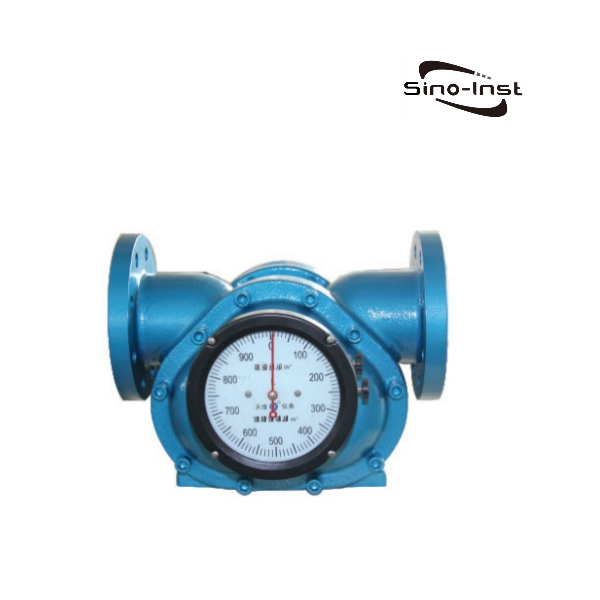
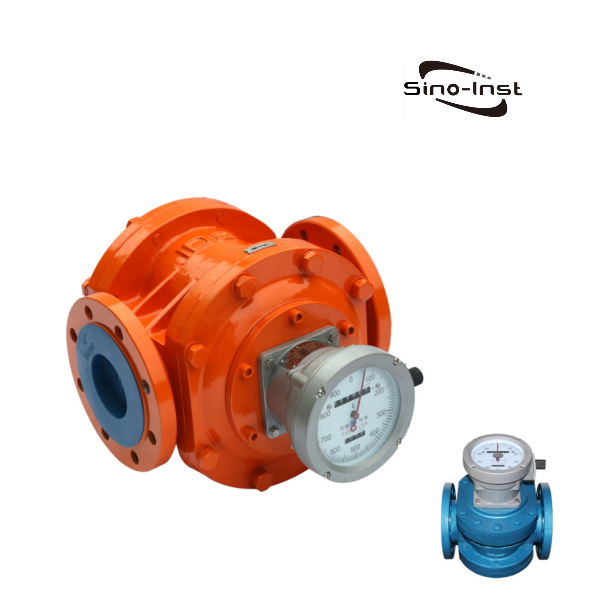
Roots Gas Meter is a high-precision, high-reliability, wide-range gas monitoring and metering instrument. The intelligent Roots Gas Meter is a new type of flow meter that integrates flow, temperature, pressure sensors and intelligent instruments based on the waist wheel flow meter.
Roots Gas Meter is an ideal instrument for measuring non-corrosive gases such as natural gas, city gas, propane, nitrogen, and industrial inert gases. There is no need for straight pipe sections before and after installation of the flow meter. Our Sino-Inst Roots Gas Meters support customization of various parameters. If you need to purchase Roots Gas Meters or have related technical questions, please feel free to contact us!
Roots Gas Meters|Volumetric-Temperature-Pressure Measure

TYL series roots gas meter is a volumetric gas meter with high precision, high reliability, wide range and low initial flow rate. It can directly measure the working volume of gas. It can be equipped with a mechanical counter or a photoelectric direct-reading counter. Various volume correctors can also be optionally equipped to achieve gas temperature and pressure measurement and volume conversion.
Product SKU: TYL Series Roots Gas Meter
Product Brand: Sino-Inst
Product Currency: USD
Product Price: 1699
Price Valid Until: 2029-09-09
Product In-Stock: InStock
5
-1.jpg)
