Home > Blog > A Comprehensive Analysis of Mechanical Water Flow Meters
A Comprehensive Analysis of Mechanical Water Flow Meters
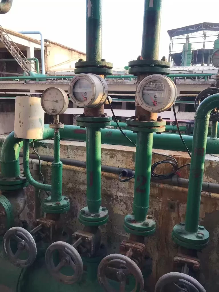
Mechanical flow meters measure water flow by measuring the movement of mechanical components such as gears, propellers, or rotors. They typically display the flow rate using a pointer or gear-based control panel. Generally, they do not require a power source.
Mechanical flow meters are reliable flow meters used to accurately measure water consumption in various industries and environments. Understanding the types, principles, and applications of mechanical flow meters can help us select the appropriate one and further optimize water resource management.
Mechanical water flow meters come in various types, each suited to specific applications and flow measurement needs. The most common types include:
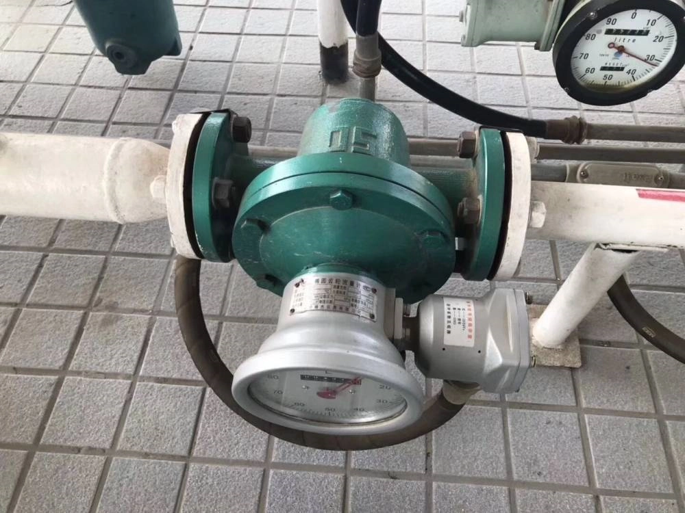
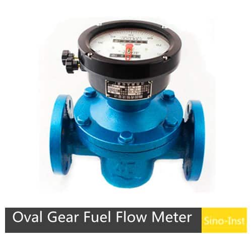
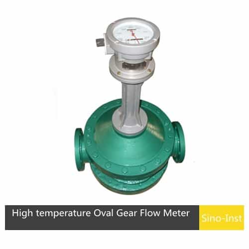
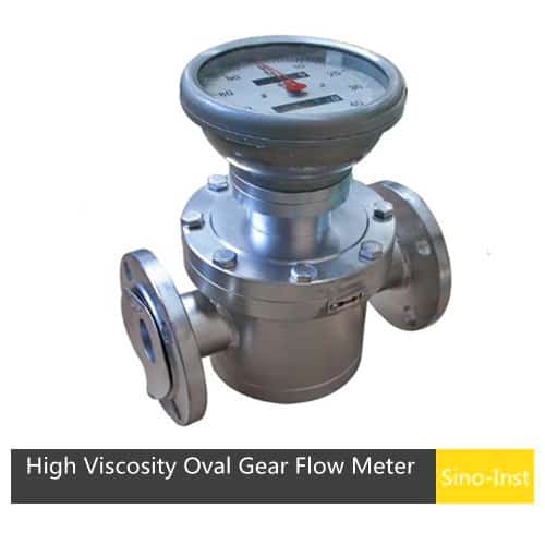
Oval Gear Flow Meters: Measure flow rate through the rotational motion of two meshing oval gears under pressure differential. Accuracy can reach 0.2%~0.5%.
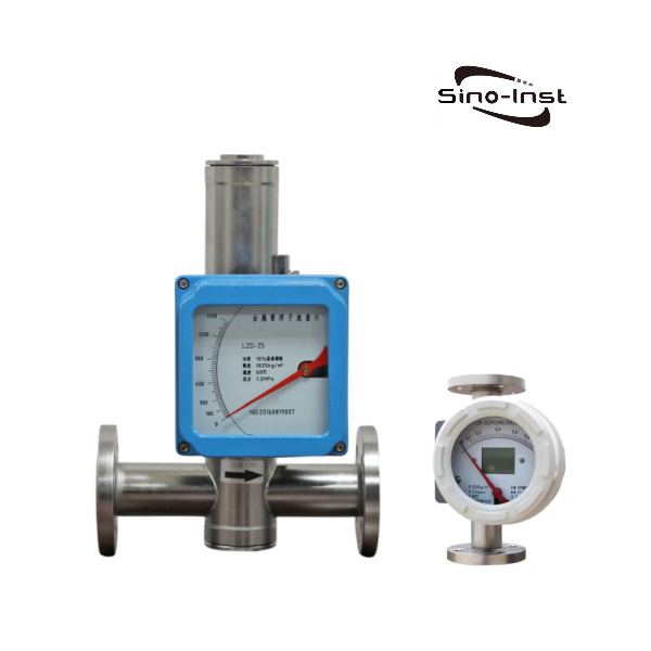
Metal Rotameters: Measure fluid flow rate by the positional change of a float within a tapered tube. Suitable for high-temperature and high-pressure flow measurement. Accuracy can reach 1.5%.
Rotary Vane Meters: These utilize a series of vanes that rotate with the flow of water, providing accurate measurements for low to moderate flow rates.
Turbine Flow Meters: Featuring a turbine wheel that spins as water passes through, these are widely used for their precision and reliability.
Piston or Reciprocating Meters: These employ pistons moving within cylinders, typically used in larger industrial settings.
Nutating Disc Meters: These use a disc that wobbles or nutates as water flows, suitable for clean water applications.
Oscillating Piston Meters: These measure flow by the oscillations of pistons driven by water movement.
Understanding the different mechanical water flow meter types helps in selecting the appropriate device for specific needs, whether for residential, commercial, or industrial water management.
Mechanical Water Flow Meter Working Principle
The core principle behind a mechanical water flow meter involves translating the kinetic energy of flowing water into measurable mechanical movement. For example:
In turbine meters, water flow causes a turbine wheel to spin, and the rotation speed directly correlates with the flow rate.
In an Oval Gear flow meter, the core components are two meshing elliptical gears and a metering chamber. When fluid passes through the flow meter, the pressure difference in the fluid drives the gears to rotate. Each rotation of the gears discharges a fixed volume of fluid.
In a metal rotor flow meter, flow rate is measured by the balance between the force exerted by the fluid flow on a float and the float’s weight and buoyancy. When fluid flows in from the lower end of the tapered tube, the fluid flow exerts an upward force on the float. The magnitude of this force is proportional to the flow rate. As the flow rate increases, the float is lifted to a new equilibrium position. At this point, there is a direct correlation between the float’s height within the tapered tube and the flow rate.
These devices typically incorporate gears or mechanical counters to record the total volume of water passing through, providing a reliable and straightforward way to how to measure water flow rate accurately.
Mechanical Water Flow Meter Specification
In industry, the two most commonly used types of mechanical water flow meters are oval gear flow meters and metal rotor flow meters. The specifications of both of them are as follows:
Rotameter Flow Meters-Metal Variable Area Flow Meters
Measuring range
Water (20℃): 1-200000 L/h Air (20℃, 0.1013MPa): 0.03~4000m³/h
Turndown
Standard type 10:1, special type 20:1
Accuracy
Gas 2.5%FS; Liquid 1.5%F.S
Pressure Level
Standard type: DN15-N50 4.0MPa; Special type: DN15-N50 25 MPa; The pressure rating of the jacket is 1.6MPa. For special models, please consult and confirm before selecting and ordering.
pressure loss
2kpa-20kpa
Medium temperature
Standard type: -40℃~100℃; PTFE: 0℃~120℃; High temperature type: 100℃~450℃;
Remote transmission type: 40℃~185℃ (the liquid crystal will not be damaged), the liquid crystal normally works at -30℃~80℃; local pointer type: -40℃~100℃
Connection Type
Connection method: flange connection standard HG20592-2010, DIN 2501 standard flange; or produced according to customer requirements; Threaded connection: produced according to diameter or customer requirements; Sanitary clamp connection: produced according to diameter or customer requirements;
Cable interface
The flameproof type is 1/2NPT internal thread; other M20*1.5 internal thread;
Power supply
Standard type: 24VDC two-wire system 4-20mA (12VDC-32VDC); Alarm type: 24VDC three-wire system 4-20mA (18VDC-28VDC); AC type: 85-265VAC50Hz; Battery type: 3.6V, 7.5AH battery, used continuously for three years;
Load characteristics
Two-wire system: RLmax=50*(-12)Ω=600Ω@24V Alarm type: the maximum load resistance is 200Ω AC type: the maximum load resistance is 200Ω
When selecting a mechanical water flow meter, several specifications are crucial:
Flow Range: The minimum and maximum flow rates the meter can accurately measure.
Size: For example, a mechanical water flow meter 2 inch is suitable for larger pipes and higher flow rates.
Accuracy: Usually expressed as a percentage of reading, important for precise water measurement.
Pressure Rating: The maximum pressure the device can withstand without malfunction.
Material: Commonly brass, stainless steel, or plastic, depending on water quality and environment.
Mechanical Water Meter Price: Varies based on size, accuracy, and features, with mechanical water flow meter price ranging from affordable models to high-precision industrial units.
Understanding these mechanical water flow meter specifications ensures optimal performance and longevity in your water measurement applications.
Measuring hot water requires a mechanical flow meter that can withstand elevated temperatures and pressures. These meters are constructed with materials resistant to thermal expansion and corrosion, such as stainless steel or specialized plastics.
When selecting a mechanical water flow meter for hot water, consider:
Temperature limits specified by the manufacturer. For example, an oval gear flow meter can withstand up to 280°C, while a metal rotor flow meter can withstand up to 450°C.
Compatibility with the piping system.
Calibration for hot water conditions to ensure measurement accuracy.
Pressure rating. For example, a standard water flow meter withstands 1.6 MPa. Custom-made meters can meet pressures of 2.5 MPa, 4 MPa, etc.
Using the right mechanical water meter for hot water applications guarantees reliable readings and durability over time.
Converting a steady water flow into a pulsed signal can be useful for various monitoring and control applications. Some methods include:
Flow Modulation Devices: Installing valves or flow restrictors that intermittently open and close to create pulsed flow.
Electronic Interfacing: Using sensors attached to the mechanical water flow meter that generate pulse signals corresponding to flow increments.
Mechanical Modulation: Employing mechanical devices like rotary or oscillating components that naturally produce pulsed outputs as water flows.
Understanding how to measure water flow rate and manipulate flow characteristics allows for better integration with automation systems and data logging devices, enhancing water management efficiency.
A clamp-on ultrasonic flow meter is an instrument that uses high-precision ultrasonic sensing technology to measure flow rate. It mainly consists of a host and a set of ultrasonic sensors. These sensors can be installed on the outer wall of the pipe without the pipe or shutting down the system, and they will not contaminate … Read more
An ultrasonic liquid flow meter is a non-contact flow measurement instrument. It uses ultrasonic waves to measure the velocity of a given fluid or gas. It calculates the flow rate by detecting the difference in forward and reverse sound wave propagation. It has no pressure loss and is widely applicable. It is widely used in various … Read more
Cooling water flow meters are used to monitor cooling water flow. They are commonly used in cooling towers, circulation systems, pipes, tanks, and pumps. They are crucial for industries such as power plants and pumping stations. Sino-Inst’s cooling water flow meters can be configured with a local digital display showing flow velocity, instantaneous flow, and … Read more
A metal tube float flowmeter (metal tube rotor flowmeter) is a variable area flowmeter commonly used in industrial automation process control. It features a compact size, wide detection range, and ease of use. It can be used to measure the flow of various liquids, gases, and other gases. It is particularly suitable for measuring low … Read more
For sustainable development strategies, companies usually install industrial wastewater treatment equipment. Install monitoring instruments such as Sewage Flow Meters and Effluent Flow Meters to monitor wastewater treatment and discharge. In this blog post, we’ll dig into what sewage and effluent flow meters are!! It will give clients a broader perspective of wastewater flow measurement. What … Read more
There are several types of flow meters designed to measure the flow of dirty water fluids, and they work in slightly different ways. The electromagnetic flow meter solution is best for measuring the flow of dirty water such as mining slurries, wastewater plants, etc. Unlike standard water meters used for clean water applications, these specialized … Read more
Drinking water is possibly the most widely acknowledged and regulated water type measured by flow meters. The water is typically treated in a municipal water treatment plant, and from there, it flows through a network of pipes to homes, businesses, and other set-ups. Flow meters in drinking water systems ensure that the correct amount of … Read more
A water flow meter can measure, monitor, and aid to control the flow of water through a pipe, hose, or other manner of instrumentation. It can provide a constant reading of the water flow rate. Measuring saltwater flow is a relatively complex process due to the corrosive nature, high salinity, and large temperature variations of … Read more
Raw water is water that has not undergone any treatment. It is found in natural sources and reserves, in surface and groundwater bodies. Likewise, fresh water is also found naturally on the Earth’s surface, such as ice, wetlands, ponds, lakes, rivers, streams, and groundwater. It usually has a low concentration of dissolved salts and solids. … Read more
A method by which we can measure the amount of heat involved in a chemical or physical process is known as Calorimetry. Calorimetry is used to measure the amount of heat transferred into or from a substance. Among the several types of flow meters available, the calorimetric flow meter stands out for its reliability, preciseness, … Read more
In summary, mechanical water flow meters are essential tools for accurately measuring water consumption in various environments. By understanding their types, working principles, specifications, and applications (including hot water measurement and flow regulation), you can make informed decisions to optimize water resource management and ensure reliable operation. Whether you’re interested in a 2-inch mechanical water flow meter or want to learn about pricing options, feel free to contact us!
Zhang Wei, possesses 20 years of experience as an automation instrumentation engineer, specializing in the research, design, installation, commissioning, and maintenance of automation instruments.
Face to various instrument communication protocols (such as Modbus, Profibus, etc.), with solid hardware circuit design and software programming skills (proficient in C language and PLC programming). Has extensive project experience; projects he has led and participated in have all achieved outstanding results, improving product accuracy, reducing costs, and increasing production efficiency.
Possesses excellent communication and coordination skills and a strong team spirit, enabling him to quickly respond to customer needs and provide high-quality automation instrumentation solutions.