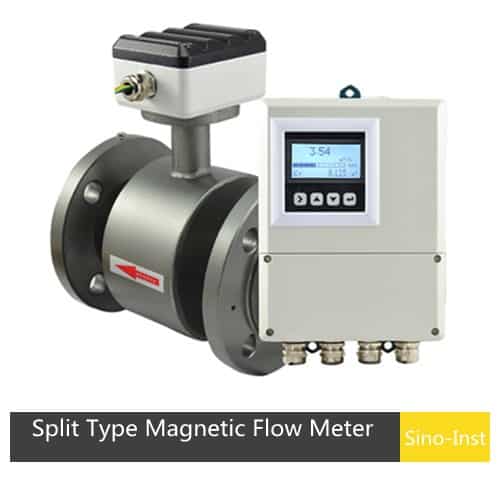
Magnetic type flow meters are based on the Faraday principle of electromagnetic induction and are used to measure the flow of liquids with conductivity greater than 5µS/cm. The split design is suitable for high-temperature, outdoor, or special environments. The sensor is submersible. The transmitter meets explosion-proof requirements.
This split-mount smart flow transmitter displays instantaneous and accumulated flow rates, and outputs pulse and analog current signals for fluid flow measurement and control.
It can measure the flow rate of general conductive liquids;
It can measure liquid-solid two-phase flow;
It can measure high-viscosity liquids as well as salts, strong acids, and strong bases.
The high-definition backlit LCD display is easy to use, simple to operate, and easy to understand.
The use of SMD components and surface mount (SMT) technology ensures high circuit reliability.
The ultra-low EMI switching power supply accommodates a wide range of power supply voltages and provides excellent EMC resistance.
It features digital communication signal outputs such as RS485, RS232, HART, and Modbus.
Power-off protection ensures that flowmeter calculation results and user-set parameters remain unchanged after a power outage. An EEPROM protects set parameters and accumulated values.
The converter and sensor are available in a variety of protection levels and mounting options. An IP68 rating is available for submersible installation.
Specifications
RS485, GPRS,Hart
Medium
Acid, alkali, salt and other corrosive medium in chemical industry
Diameter
DN6~DN2200mm
Accuracy
±0.5%
Medium temperature
<60℃
Nominal pressure
GB 0.6MPa (DN700~DN2200)
GB 1.0MPa (DN200~DN600)
GB 1.6MPa (DN6~DN150)
DIN PN16,PN25,PN40,PN63
JIS10K,20K,40K
ANSI Class150,Class300,Class600, others can be customized
Sodium hydroxide, ammonium hydroxide alkali solution and weak organic acid
Medium
316L
Domestic water, industrial water, raw water, urban sewage, etc.
Hastelloy B (HB)
1. Salt solution (chloride, sodium salt, potassium salt, ammonium salt, sea water, etc.)2. Alkaline solution (such as a concentration less than 50% potassium hydroxide solution)
Hastelloy C (HC)
Oxidizing salt solution (Fe+++, Cu++, seawater)
Titanium (Ti)
1. Salt solution (chloride, sodium salt, potassium salt, ammonium salt, sea water, etc.)2. Alkaline solution (such as concentration less than 50% potassium hydroxide solution)
Tantalum(Ta)
1. Hydrochloric acid, sulfuric acid, oxidizing acid, aqua regia 2. Chlorine dioxide, ferric chloride, hypochlorous acid, sodium cyanide, lead acetate, etc.
Platinum (Pt)
Acid, alkali, salt solution
Tungsten carbide (WC)
Handled neutral industrial sewage and domestic sewage. Resistant to solid particle interference
Lining material selection
Lining material
Linner
Temperature
Suitable medium
Diameter
Rubber
Neoprene(CR)
-20~60℃
Slurry, paper pul,p etc.
DN65~DN1600
Natural Rubber(NR)
Polyurethane Rubber(PU)
Slurry, paper pulp etc.
DN25~DN500
Silicone rubber
-20~180℃
Water
DN40~DN1600
Fluoroplastic
PTFE(F4)
-20~120℃
Corrosive acid-base salt liquid
DN10~DN1600
Teflon F46(FEP)
-40~160℃
Corrosive acid-base salt liquid
DN10~DN200
PFA
-40~160℃
Corrosive acid-base salt liquid
DN10~DN300
Integrated vs. Split Structure
An integrated electromagnetic flowmeter combines the sensor and converter into a single, integrated structure. This compact design reduces pipeline installation workload and simplifies installation and maintenance.
A split-type electromagnetic flowmeter consists of a sensor and a converter. The sensor is installed on the measuring pipe to detect fluid flow. The converter, installed at a certain distance from the sensor (usually no more than 100 meters), receives the sensor signal, processes it, and displays and outputs it. This structure allows for flexible placement and combination of the sensor and converter, tailored to specific needs.
Installation of an integrated electromagnetic flowmeter requires simply mounting the entire device on the pipe, eliminating the need for additional wiring. This simple and quick installation method is ideal for applications with limited space or restricted installation conditions.
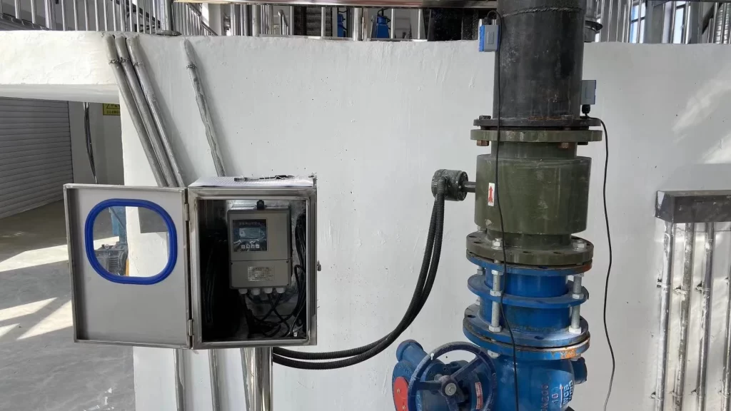
Installation of a split-type electromagnetic flowmeter requires installing the sensor separately on the pipe and connecting it to the converter via a cable. This installation method is more complex and requires more wiring, but it can be flexibly adjusted to suit the site’s environment.
With its compact structure and advanced communication capabilities, the integrated electromagnetic flowmeter is suitable for applications with limited space and a high demand for data exchange.
Because the sensor and converter can be installed separately, split-type electromagnetic flowmeters are suitable for applications where the on-site measurement environment is poor and remote display is required. For example, in environments with high temperature, high humidity, high vibration, or corrosive gases, split-type electromagnetic flowmeters can ensure the accuracy and stability of measurement data.
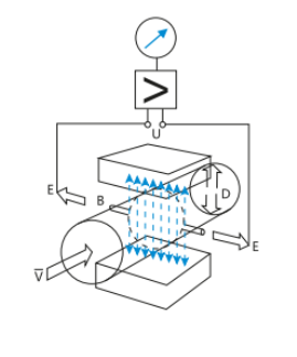
The operating principle of an electromagnetic flowmeter is based on Faraday’s law of electromagnetic induction. The two electromagnetic coils at the upper and lower ends of the diagram generate a constant or alternating magnetic field. When a conductive medium flows through the electromagnetic flowmeter, an induced electromotive force (EMF) is detected between the left and right electrodes on the flowmeter tube wall. The magnitude of this induced EMF is proportional to the flow velocity of the conductive medium, the magnetic flux density of the magnetic field, and the conductor width (the inner diameter of the flowmeter tube). Through calculation, the flow rate can be calculated.
The process parameter equation for the induced EMF is:
E=KBV*D
Where: E – induced EMF; D – inner diameter of the measuring tube; B – magnetic flux density; V – average flow velocity; K – coefficient related to magnetic field distribution and axial length;
Electromagnetic flowmeters can achieve an accuracy of 0.5% FS, meeting the requirements of most measurement conditions. Of course, the accuracy of electromagnetic flowmeters is also affected by various factors.
Fluid Conductivity
Electromagnetic flowmeters operate based on Faraday’s law of electromagnetic induction. Liquid conductivity affects the magnitude and stability of the induced electromotive force. When the fluid conductivity is too low, the induced electromotive force is weak, and the signal is easily overwhelmed by noise, resulting in increased measurement error.
For example, when measuring low-conductivity fluids such as deionized water, the conductivity may fall below the lower limit of the electromagnetic flowmeter’s normal measurement range, significantly reducing measurement accuracy.
Fluid Velocity Distribution
Ideally, a fluid in a pipeline should exhibit a fully developed, axisymmetric velocity distribution. However, in practice, localized resistance components such as elbows, valves, and reductions or expansions can distort the fluid velocity distribution. This results in uneven velocity at various points within the measuring tube, affecting measurement accuracy.
Fluid Density and Viscosity
Generally, electromagnetic flowmeters measure volumetric flow, which is theoretically unrelated to fluid density and viscosity. However, in certain special circumstances, such as when high-viscosity fluids flow through pipes, wall slip may occur, affecting the flow velocity distribution and, in turn, indirectly impacting measurement accuracy.
Bubbles or solid particles in the fluid
Bubbles in the fluid occupy a certain amount of space in the pipe, reducing the actual volume of fluid involved in the measurement. Furthermore, the movement of bubbles in the magnetic field may generate additional interference signals. Solid particles may abrade the electrodes and lining, affecting the stability of the measurement signal.
Installation Location
The electromagnetic flowmeter should be installed on a straight pipe section where the pipe is filled with fluid and the flow velocity distribution is uniform. Improper installation, such as near areas with strong disturbances such as pump outlets or valves, can cause unstable flow patterns and affect measurement accuracy.
Straight Pipe Length
Depending on the flowmeter diameter and upstream pipe conditions, the upstream straight pipe section is generally required to be 5-10 pipe diameters long, and the downstream straight pipe section is 3-5 pipe diameters long. If the actual straight pipe section length does not meet the requirements during installation, measurement accuracy will be affected.
Pipeline Vibration
Pipeline vibration can cause minute displacements in the electromagnetic flowmeter’s measuring tube and electrodes, resulting in changes in the induced electromotive force (EMF), which can introduce measurement errors.
Stray Current Interference
Principle: Various stray currents may exist in industrial sites, such as those generated by poor grounding and improper cable routing. These stray currents can generate interference signals in the electromagnetic flowmeter’s measuring circuit, affecting measurement accuracy.
For example, if the electromagnetic flowmeter’s grounding system is inadequate near high-voltage equipment, stray currents may enter the measuring circuit through the ground wire, causing measurement errors.
Magnetic Field Interference
Strong external magnetic fields can interfere with the electromagnetic flowmeter’s own magnetic field, changing the strength and direction of the magnetic field within the measuring tube, thereby affecting the induced electromotive force measurement.
Improper Electrode and Lining Material Selection
The electrode and lining materials should be compatible with the chemical properties of the fluid being measured. Improper material selection can cause corrosion to the electrodes and wear or dissolve the lining, affecting the accuracy and stability of the measurement signal.
Instrument Aging and Wear
Over time, electromagnetic flowmeter components such as electrodes, linings, and coils will age and wear. Electrode surfaces may scale and oxidize, linings may thin and crack, and coil insulation may degrade, all of which can affect measurement accuracy.
Temperature Changes
Ambient temperature fluctuations can affect the performance of the electromagnetic flowmeter’s electronic components, coil resistance, and the fluid’s physical properties (such as viscosity and conductivity). These changes in electronic component performance can alter measurement circuit parameters, affecting measurement accuracy.
Humidity Effects
High humidity environments can cause moisture to build up in the electromagnetic flowmeter’s electronic components, degrading insulation performance and introducing measurement errors. Furthermore, humidity can affect the contact resistance between the electrodes and the fluid, hindering measurement signal transmission.
The electromagnetic flowmeter can display both instantaneous and cumulative flow rates. Flow units can be configured according to user requirements.
Users can select the appropriate flow display unit based on process requirements and usage habits.
Mass flowmeters have a wide range of applications, measuring the flow of various liquid and gaseous media. They are ideal for applications requiring precise mass flow measurement, such as flow measurement in the chemical, pharmaceutical, and food industries.
Electromagnetic flowmeters are suitable for measuring the flow of conductive media such as acids, alkalis, electrolytes, and wastewater. However, they offer limited accuracy for non-conductive media such as liquefied petroleum gas.
Flow meters are commonly used measuring devices in industrial production and scientific experiments. They are used to measure the flow of fluid in pipes. The accurate reading of flow meter readings plays an important role in enterprise production and safety management. This article will introduce in detail how to correctly read the flow meter, ground … Read more
Flow meter accuracy directly impacts a manufacturer’s profitability and operational integrity. A flow meter is more than just a process instrument; it’s a critical tool. Understanding flow meter accuracy and related parameters is crucial for process control, quality assurance, and cost-effectiveness across various industries. What Is Flow Meter Accuracy? Flow meter accuracy is the degree … Read more
Cooling water flow meters are used to monitor cooling water flow. They are commonly used in cooling towers, circulation systems, pipes, tanks, and pumps. They are crucial for industries such as power plants and pumping stations. Sino-Inst’s cooling water flow meters can be configured with a local digital display showing flow velocity, instantaneous flow, and … Read more
Accurate flow measurement is crucial for process control. Before purchasing a flow meter, you should consider the installation requirements. The meter’s installation location and the length of upstream and downstream straight pipe runs directly affect the accuracy of the measurement results. Are Straight Pipe Runs Necessary for Flow Meters? In fact, the answer is not … Read more
Slurry and sludge flow measurement is complex and challenging. Accurately measuring slurry flow can improve efficiency and reduce costs in industries such as wastewater treatment, water conservancy projects, river dredging, and oil well cementing. Slurry flow meters measure the volumetric flow of sludge and slurries in pipelines. Examples include cement slurry, mud, pulp, various acid, … Read more
Ultrasonic vs Magnetic Flow Meter, are you confused about which one to choose? Sino-Inst, based on our years of experience in flow measurement services, has compiled this blog, hoping to help you! Ultrasonic flow meters and electromagnetic flow meters are both commonly used liquid flow meters. Because of their different working principles, they both have … Read more
Cement additives are chemical additives added during the production and use of cement. They improve the overall performance of cement products by adjusting the setting time, improving rheological properties, and enhancing durability. The main types include water reducers, retarders, early strength agents, and expansion agents. Liquid Cement Additive is a state of mixed solvent. The … Read more
Insertion Magnetic Flow Meters are configured for use with conductive liquids in DN100~DN3000 (4″ ~ 120″) pipe. A selection of materials (stainless steel, brass, and PVC) allows the meter to adjust to a range of temperatures, pressures, and corrosive environments. With no moving parts, these meters can be used in “dirty” applications where debris would … Read more
Battery Operated Flow Meters are powered by internal batteries and do not require external power supply. They are widely used in working conditions where there is no power supply in the field or the power grid is difficult to lay. The general battery is a lithium battery, which can support several years of measurement. Most … Read more
A method by which we can measure the amount of heat involved in a chemical or physical process is known as Calorimetry. Calorimetry is used to measure the amount of heat transferred into or from a substance. Among the several types of flow meters available, the calorimetric flow meter stands out for its reliability, preciseness, … Read more
Magnetic flow meters are based on Faraday’s law of electromagnetic induction, measuring flow by measuring the electromotive force induced by a conductive liquid in a magnetic field. Their split structure design and PTFE lining provide significant advantages in corrosion resistance and adaptability.
Split structure magnetic flow meters feature separate sensors and converters. The sensor can be placed in high-temperature, high-pressure, or corrosive environments, while the converter is located in a safe area. Signals are transmitted via cables, protecting the electronic components from harsh operating conditions.
Sino-Inst is a professional supplier of magnetic flow meters. If you require flow measurement, please feel free to contact us.
Zhang Wei, possesses 20 years of experience as an automation instrumentation engineer, specializing in the research, design, installation, commissioning, and maintenance of automation instruments.
Face to various instrument communication protocols (such as Modbus, Profibus, etc.), with solid hardware circuit design and software programming skills (proficient in C language and PLC programming). Has extensive project experience; projects he has led and participated in have all achieved outstanding results, improving product accuracy, reducing costs, and increasing production efficiency.
Possesses excellent communication and coordination skills and a strong team spirit, enabling him to quickly respond to customer needs and provide high-quality automation instrumentation solutions.