-1.jpg)
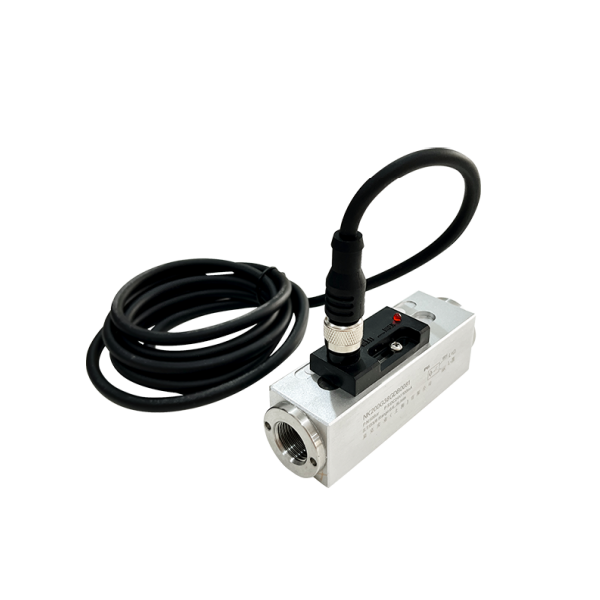
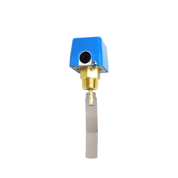
SI-210 series piston flow switch has a built-in piston with a magnet. When water flows through, the piston moves in the housing. This closes the reed switch in the electrical box outside the housing. The flow rate can be set by moving the electrical box. Online installation, mechanical flow switch, for liquid or gas media, sturdy plastic, aluminum or stainless steel housing optional.
Features
- Sturdy plastic, aluminum or stainless steel housing optional.
- Minimal pressure loss, good repeatability.
- Anti-fouling ability, complete isolation of mechanical and electronic parts, suitable for small flow rate economy.
- With switch setting scale, users do not need to set on site.
- LED displays switch status, dual switch output is available.
SI-210 Series Piston Flow Switch Technical Parameters
| Setting range | See parameter table for details |
| Accuracy | ±5% total range |
| Hysteresis | Depending on the switch point, the minimum amount is 0.5L/min |
| Switch setting scale | The calibration is carried out when the medium is water, the temperature is 20℃, and the horizontal installation state is carried out |
| Installation position | The medium and temperature changes will slightly affect the switch value |
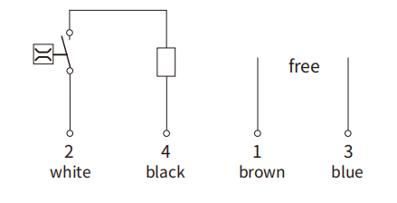
| Wiring method | M12 5-pin connector, Hirschmann connector optional. |
| LED display | DC power supply LED displays the switch status, AC has no LED display |
| Output | Reed switch, capacity 24VDC/250VAC, 100mA |
| Withstand pressure | 50bar (aluminum type), 100bar (stainless steel type) |
| Average pressure loss | 0.3bar (at 25L/min) |
| Medium temperature | Maximum 90℃ |
| Protection level | IP65 |
| Anodized aluminum (stainless steel) | |||||||||
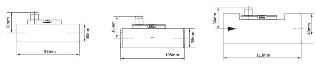
| Model | Pressure ( bar) | Maximum flow rate L/min (water) | Adjustable range L/min (water) | G(mm) | L mm | H mm | B mm | X mm | Weight (kg) |
| 210-G14…L010 | 50 | 40 | 0.6(0.1)..8(7) | G1/4 | 93 | 36 | 30 | 12 | 0.22(0.53) |
| 210-G38…L010 | 50 | 40 | 0.6(0.1)..8(7) | G3/8 | 93 | 36 | 30 | 15 | 0.20(0.51) |
| 210-G12…L010 | 50 | 40 | 0.6(0.1)..8(7) | G1/2 | 93 | 36 | 30 | 15 | 0.18(0.48) |
| 210-G34…L010 | 50 | 40 | 0.6(0.1)..8(7) | G3/4 | 105 | 36 | 35 | 15 | 0.23(0.65) |
| 210-G1…L010 | 50 | 60 | 0.6(0.1)..8(7) | G1 | 105 | 36 | 40 | 15 | 0.32(0.82) |
| 210-G14…L015 | 50 | 40 | 1(0.5)..15(13) | G1/4 | 93 | 36 | 30 | 12 | 0.22(0.53) |
| 210-G38…L015 | 50 | 40 | 1(0.5)..15(13) | G3/8 | 93 | 36 | 30 | 15 | 0.20(0.51) |
| 210-G12…L015 | 50 | 40 | 1(0.5)..15(13) | G1/2 | 93 | 36 | 30 | 15 | 0.18(0.48) |
| 210-G34..L015 | 50 | 40 | 1(0.5)..15(13) | G3/4 | 105 | 36 | 35 | 15 | 0.23(0.65) |
| 210-G1…L015 | 50 | 60 | 1(0.5)..15(13) | G1 | 105 | 36 | 40 | 15 | 0.32(0.82) |
| 210-G12…L028 | 50 | 40 | 2(0.8)..28(25) | G1/2 | 93 | 36 | 30 | 15 | 0.18(0.48) |
| 210-G34..L028 | 50 | 60 | 2(0.8)..28(25) | G3/4 | 105 | 36 | 35 | 15 | 0.23(0.65) |
| 210-G1…L028 | 50 | 40 | 2(0.8)..28(25) | G1 | 105 | 36 | 40 | 15 | 0.32(0.85) |
| 210-G34…L070 | 50 | 100 | 27(21)..70(66) | G3/4 | 105 | 36 | 35 | 15 | 0.23(0.65) |
| 210-G1…L070 | 50 | 100 | 27(21)..70(66) | G1 | 105 | 36 | 40 | 15 | 0.32(0.82) |
① The parameters in the brackets are the reset points.
② The parameters outside the brackets are the action points.
③ If the lower limit alarm (monitoring flow is too small), refer to the reset point parameters; if the upper limit alarm (monitoring flow is too large), refer to the reset point parameters.
④ The above parameters are obtained by installing the switch vertically in a horizontal pipeline and testing with 20°C water medium.
Piston Type Flow Switch Working Principle
A piston encapsulated with a permanent magnet is placed in the fluid path within the flow switch. When the pressure difference of the fluid displaces the piston, the piston will magnetically activate the SPST or SPOT reed switch encapsulated in the flow switch.
By controlling the bypass gap, the piston ring land diameter accurately corresponds to the set point.
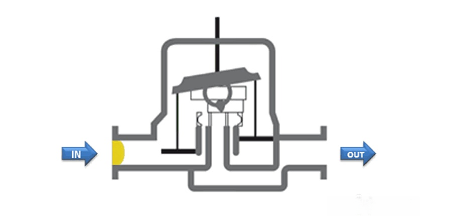
As the flow rate decreases, the stainless steel spring resets the piston. After the reed switch is actuated, it can be used to control a remote alarm or indicator, or it can be integrated into the automatic system control.
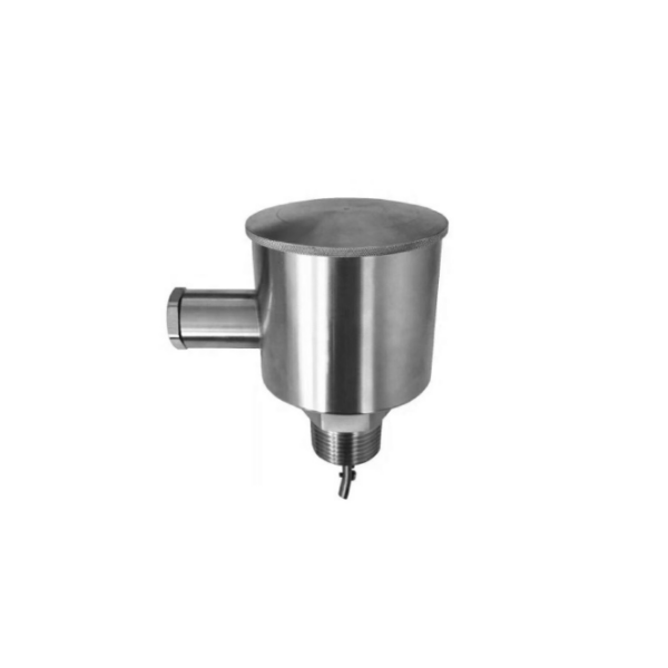
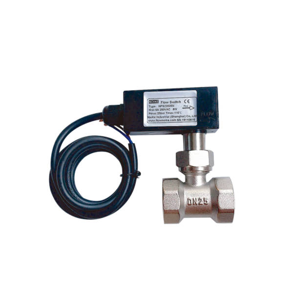
More Flow Switches
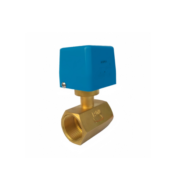
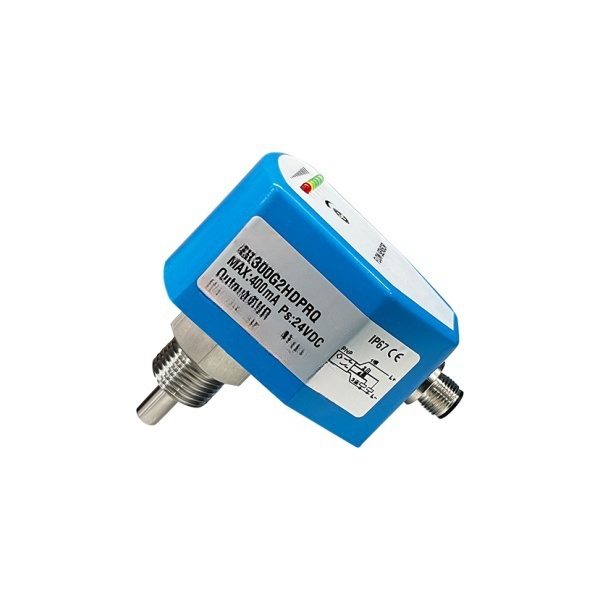
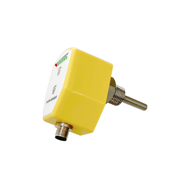
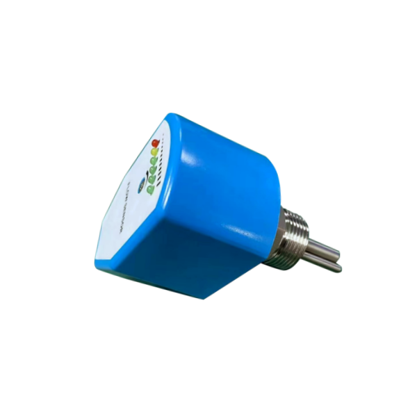
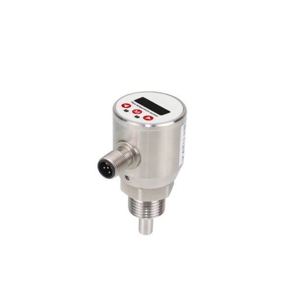
Piston flow switches are used in water circulation control, water inlet and outlet control, water heating control, water pump switch control, solenoid valve on/off control, or water outlet power-off and power-on control of electric water heaters, solar water heaters, air conditioners and other water systems. When a certain flow rate is reached, the water flow is converted into a switch-type electrical signal.
Sino-Inst supplies a variety of flow switches, including thermal conductivity, electronic, and mechanical. If you need to purchase a piston flow switch, please feel free to contact our sales engineer!