
Guided Wave Radar vs Pressure-Based Level Sensors
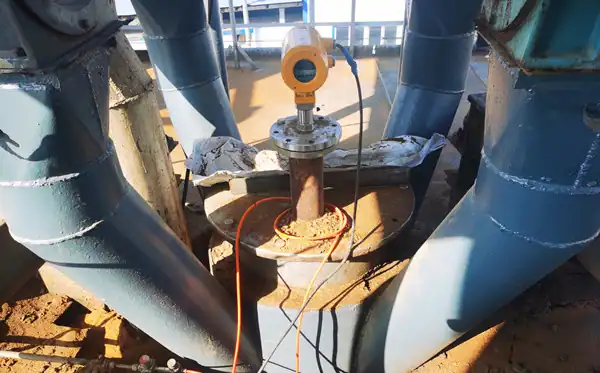
Guided wave radar and pressure-based level sensors are common contact-type instruments used for liquid level measurement in industrial storage tanks. Pressure-based level sensors represent a more traditional measurement method; they offer consistently stable performance and are highly trusted by users. Guided wave radar level transmitters utilize newer measurement technology, providing high accuracy and suitability for a wide range of complex operating conditions.
The choice between guided wave radar and pressure-based level sensors should be determined based on actual operating parameters.
Pressure-Based Level Sensors
Long before radar and ultrasonic level measurement technologies became widespread, pressure-based level measurement devices were already being used on various industrial tanks. They offer stable measurement performance at a low cost.
Working Principle
The core principle of Pressure-Based Level Sensors is static pressure measurement. By measuring the hydrostatic pressure of the liquid, the level height is converted into an electrical signal output, enabling level monitoring and control.
The pressure exerted by the liquid in a tank or pipeline is directly proportional to the liquid level height; the formula is P = ρ·g·H. Here, P represents hydrostatic pressure, ρ is liquid density, g is the acceleration due to gravity, and H is the liquid level height.
The transmitter uses a sensor to measure the pressure at the bottom of the liquid or at a specific location and converts the pressure signal into a standard current or digital signal output, such as 4-20mA, RS485, or HART protocol.
Sensor Types
The core measurement objective of Pressure-Based Level Sensors is to obtain the pressure (or differential pressure) at the bottom of the tank or a specified location. Consequently, different types of sensors have been designed based on the method of pressure acquisition. Broadly speaking, these include the following categories:
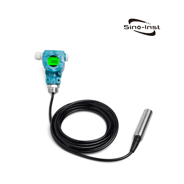
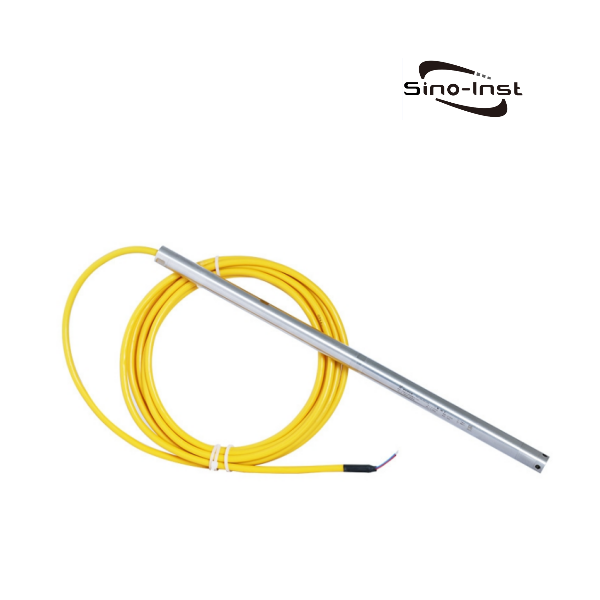
(1) Submersible hydrostatic level transmitters. The pressure sensor probe is submerged directly to the bottom of the liquid to measure hydrostatic pressure, thereby determining the liquid level. These are suitable for level measurement in tanks containing water, sewage, or oil. Deep-well level gauges with ranges up to 2000 meters can also be customized.
(2) Single-flange level transmitters. Primarily used for level measurement in open tanks. They are installed at the bottom of the tank; threaded mounting options are also available.
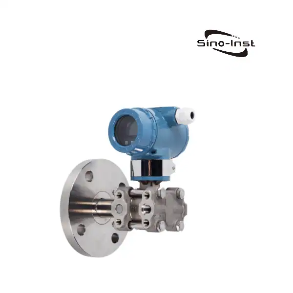
(3) Dual-flange differential pressure transmitters. Primarily used for level measurement in sealed tanks. This setup requires connecting both the high-pressure point at the bottom of the tank and the low-pressure point at the top of the tank to the differential pressure transmitter to determine the pressure difference, thereby monitoring the liquid level height.
Application Case
A client from Saudi Arabia previously inquired about the following instruments for their cryogenic process monitoring: a differential pressure (DP) level transmitter (0–1600 mbar range, 4–20 mA analog output, for oxygen level measurement, process temperature -196 to 60°C, 1/4″ NPT connection, Qty: 1) and a pressure transmitter (0–25 bar range, 4–20 mA analog output, for oxygen pressure measurement, process temperature -196 to 60°C, 1/4″ NPT connection, Qty: 1).
This represents a typical configuration for cryogenic storage tanks utilizing pressure-based measurement principles. The transmitters are installed at ambient temperature and connected via impulse lines to the liquid outlet at the tank bottom and the vapor space at the top, respectively. Differential pressure measurement cancels out the tank’s internal pressure, thereby reflecting only the hydrostatic pressure of the liquid column. Based on the density of liquid oxygen (approximately 1140 kg/m³), a differential pressure of 1600 mbar corresponds to a liquid level height of approximately 14 meters.
Featured Pressure-Based Level Sensors
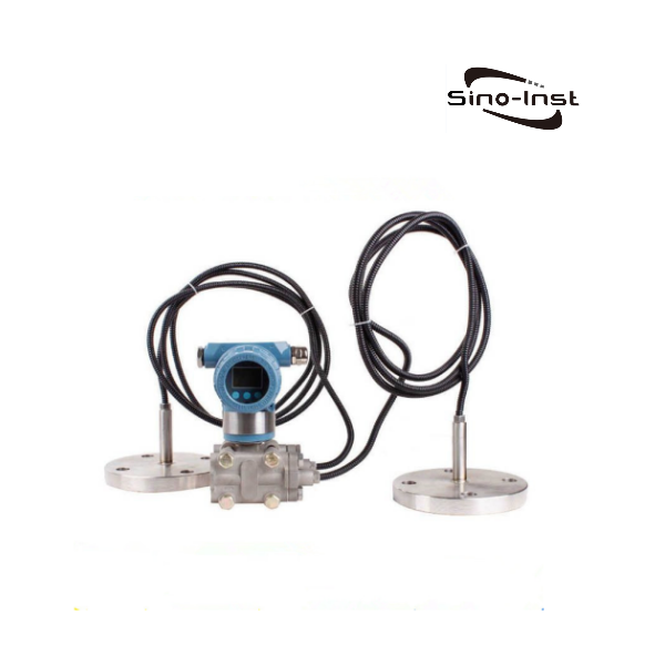
Guided Wave Radar Level Sensor
The advent of radar level measurement technology has significantly enhanced measurement accuracy. Guided wave radar level sensors employ contact-based measurement, ensuring both high accuracy and excellent stability.
Working Principle
Guided wave radar level meters operate on the principle of Time Domain Reflectometry (TDR). The core mechanism involves transmitting high-frequency microwave pulses along a probe (rod or cable) toward the liquid surface. When a pulse encounters the surface of the liquid or solid medium, a portion of the energy is reflected back to the sensor. An internal timer records the round-trip time of the microwave, and the level height is calculated using the formula: Level Height = Speed of Light × Round-trip Time / 2.
The microwave pulse travels along the probe, and the reflected echo returns along the same probe to the sensor. The signal is processed by an intelligent processor, converted into a level reading, and displayed on a terminal device; it can also trigger alarms or control operations.
Sensor Types
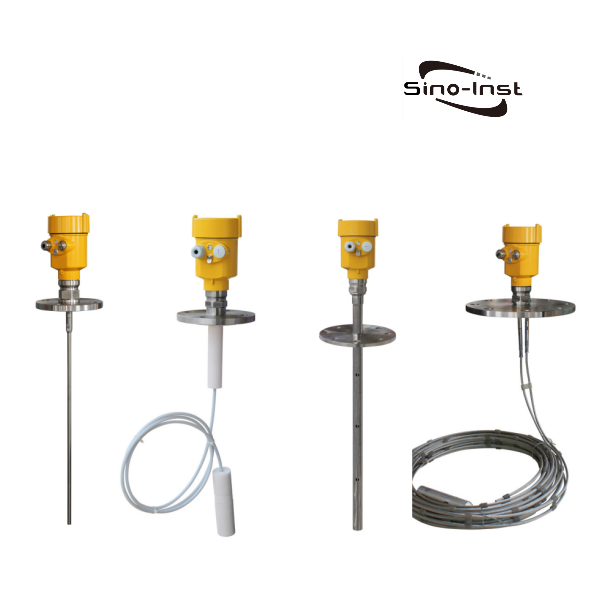
Guided-wave radar level transmitters primarily feature three types of probe assemblies: rod, cable, and coaxial.
The cable type utilizes a flexible guided-wave cable to transmit signals, allowing it to adapt easily to tanks of varying heights—particularly large or deep tanks—with a measurement range spanning 0.5 to 30 meters. Its advantages include installation flexibility and suitability for irregular tank shapes. It is ideal for measuring viscous liquids or media prone to coating the probe (such as asphalt, syrup, or sewage) and can also measure the level of solid particles (like pulverized coal or ore dust), demonstrating strong versatility.
The probe assembly of a rod-type guided-wave radar level transmitter consists of either a single metal rod or two parallel metal rods; it is primarily used in applications involving liquids that generate significant foam. Rod-type transmitters possess exceptional ability to penetrate foam and vapor. However, it is important to note that their measurement range is limited, with a maximum of 6 meters.
The coaxial guided-wave radar level transmitter consists of a metal rod and a surrounding metal tube, with radar waves propagating through the annular space between them. Compared to the rod type, this configuration concentrates energy more effectively, minimizes signal dispersion, and reduces susceptibility to external interference. Consequently, coaxial transmitters are better suited for measuring levels of media with low dielectric constants. Data indicates that coaxial radar level transmitters can detect reflection signals from liquid media with dielectric constants as low as 1.5.
However, the maximum measurement range for this type is also 6 meters. If the required range exceeds 6 meters, a cable-type guided-wave radar level transmitter should be considered. The primary difference between coaxial/rod-style guided wave radar (GWR) level transmitters and cable-style versions lies in their measurement ranges. Meanwhile, the main distinction between coaxial and rod styles is their suitability for specific operating conditions: rod-style probes are well-suited for applications prone to buildup or scaling, whereas coaxial probes are not recommended for such environments.
Application Case
A personal care product manufacturer in Bangladesh sought a cost-effective continuous level measurement solution for its stainless steel shampoo storage tanks (capacities of 3,000–6,000 liters, heights of 2–3.5 meters, and temperatures up to 45°C). The technologies considered by the customer included radar, hydrostatic pressure, and ultrasonic sensors.
Before finalizing the selection, we asked whether foam was present in the tanks. The answer was affirmative; the foam thickness varied by batch, and the specific gravity of the product fluctuated between 0.95 and 0.99. This ruled out non-contact radar, as foam scatters and absorbs free-space radar signals. Hydrostatic pressure sensors were also unsuitable: the specific gravity fluctuation (0.95–0.99) would cause a deviation of approximately 4% in pressure-based readings, and a submersible probe installed at the bottom of a sanitary tank would not support Clean-in-Place (CIP) procedures.
We recommended a guided wave radar transmitter featuring a 1.5-inch Tri-clamp connection, wetted parts made of SS316L/PTFE, a 4–20 mA two-wire output, and a local display. This instrument is unaffected by density or foam and can be installed directly onto the existing sanitary nozzle at the top of the tank.
Featured Guided Wave Radar & Radar Level Transmitters
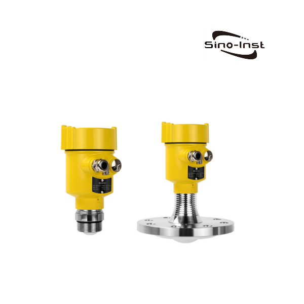
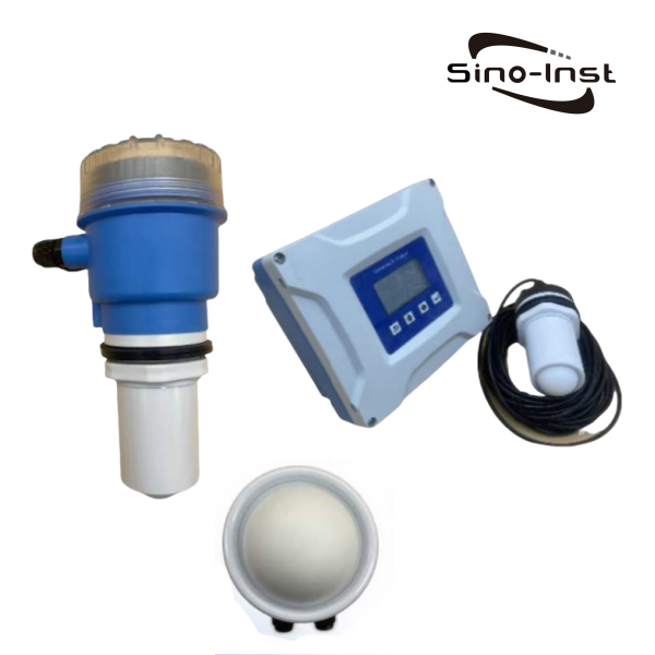
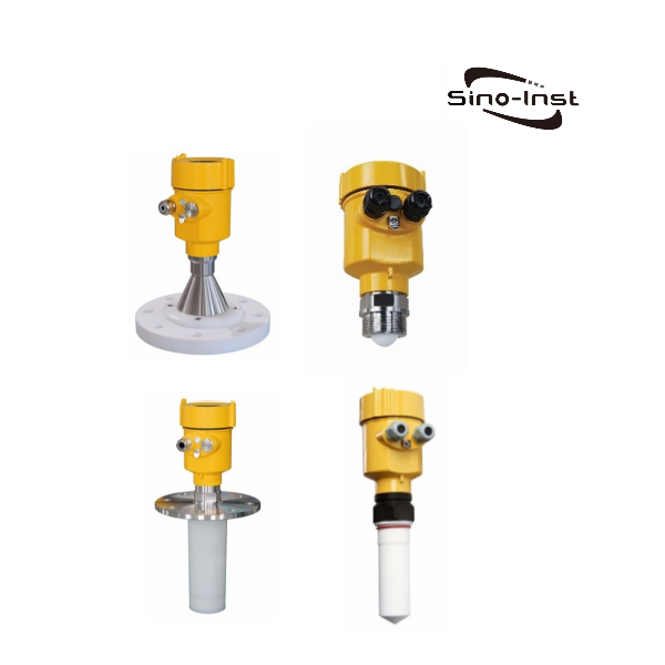
Comparison of Guided Wave Radar vs. Pressure-Based Level Sensors: Pros and Cons
| Item | Guided Wave Radar | Pressure Types (Submersible / Flange / Differential Pressure) |
| Measuring range | 6 m (coaxial) / 15 / 20 / 30 m (limited by probe length) | Submersible: 0–1 m to 200 m (deep-well type up to 2000 mH₂O); Differential Pressure: 4 kPa–10 MPa (approx. 0.4 m to 1000 m water column). |
| Accuracy | ±5 mm, ±10 mm | 0.1–0.5% FS |
| Effect of medium density | Unaffected | Direct impact: Reading is proportional to density; recalibration is required if the medium or density changes. |
| Effect of dielectric constant | Thresholds apply: liquids >1.6; rod type ≥1.8; ≥1.3 with stilling well | Unaffected |
| Maximum process temperature | Standard 130°C; high-temp version 250°C; Model 705 up to 400°C (low temp down to -200°C) | Submersible general-purpose type: 85°C; high-temperature type: customizable up to 600°C; |
| Corrosive media | Model 702 is fully PTFE-encapsulated (limited to 0.3 MPa, 200°C) | PTFE submersible type; flange diaphragm options include Hastelloy, Tantalum, Monel, and PTFE (wider selection). |
| Solids / Powders | Models 701 and 703 are suitable for this application | Cannot measure |
| Viscous / Buildup-prone | Viscosity ≤500 cSt; single-rod resists material buildup, whereas coaxial and twin-rod types are prone to buildup causing false echoes | Flush-diaphragm flange: anti-clogging design, suitable for paste-like media; submersible type: must avoid sediment at the tank bottom. |
| Agitation / Turbulence | Probe susceptible to impact from agitators; stilling well can be used to avoid agitation-induced turbulence/vortices | Submersible type: must avoid inlets/outlets and agitators; use steel wire or a protective sleeve in cases of strong turbulence. |
| Installation | Tank top mounting; distance from tank wall ≥300 mm, from obstacles ≥200 mm; nozzle length ≤100 mm | Submersible type: no tank opening required (simply lowered in), but cable length must be determined upfront; flange and differential pressure types: require an opening at the tank bottom or side. |
Advantages of Guided Wave Radar
- Measures distance; unaffected by density, temperature, tank pressure, or steam; no recalibration needed when changing media.
- Accuracy is measured in millimeters (±5–10 mm) and does not degrade as the measuring range increases; the advantage becomes more pronounced with longer ranges.
- Wide temperature and pressure ranges: Model 705 handles -200 to 400°C and 40 MPa; capable of measuring vacuum tanks.
- Measures both liquids and powders (Models 701/703; max range 30 m).
- Requires only one opening at the top of the tank; no bottom opening is needed, eliminating the risk of bottom leaks.
- Less affected by light foam and steam compared to non-contact radar.
Disadvantages
- Has a dielectric constant threshold: >1.6 for liquids, ≥1.8 for rod-type probes. Requires a waveguide or coaxial probe for media like liquid oxygen, liquid nitrogen, and certain hydrocarbons.
- Viscosity limit ≤500 cSt; coaxial and twin-rod probes are prone to material buildup, and buildup with a high dielectric constant can generate false echoes.
- Has upper and lower dead zones; the maximum liquid level must not enter the dead zone.
- Strict installation requirements: ≥300 mm from tank walls, ≥200 mm from obstacles, nozzle length ≤100 mm; requires a suitable opening at the top of the tank.
- Measuring range is limited by probe length (6 m for rod-type, 30 m for cable-type); unsuitable for extremely deep wells or reservoirs.
- Price is significantly higher than submersible pressure sensors.
Advantages of Pressure-Based Level Sensors
- Simple structure and low cost. Submersible types require no tank openings—simply lower them in to use; suitable for reservoirs, wells, waterways, and open tanks.
- Wide measuring range: from 1 m up to 2,000 mH₂O for deep wells.
- High accuracy at short ranges: 0.2% FS equates to approximately ±2 mm for a 1 m range.
- Unaffected by foam, dielectric constant, or internal tank obstacles. Multiple anti-corrosion options: PTFE probes; Hastelloy, tantalum, or Monel diaphragms.
- Differential pressure (DP) models can measure sealed pressurized tanks and cryogenic tanks (e.g., liquid oxygen), as well as interface levels and density (SI-3151LT).
Disadvantages
- Readings are directly linked to medium density: changes in the medium, temperature, or formulation introduce errors (e.g., readings are ~16% low for diesel and ~20% high for ammonium sulfate).
- Accuracy is calculated as a percentage of full scale (%FS); the wider the measurement range, the larger the absolute error (e.g., 0.5%FS on a 10 m range results in an error of approx. ±50 mm).
- Submersible types are suitable only for open tanks. Sealed tanks require DP transmitters, which necessitate two pressure taps and the handling of impulse lines or capillary tubes.
- Remote-seal DP transmitters are not suitable for vacuum applications; PTFE submersible types are limited to 70°C, while standard submersible types are limited to 85°C.
- Requires contact with the medium: bottom sediment, crystallization, and agitation impact readings; submersible types also require secure mounting.
- Submersible cable length must be specified at the time of order (cables include a vent tube and cannot be extended on-site); not convenient for CIP (Clean-in-Place) procedures in sanitary tanks.
- Cannot measure solids or powders.
How to Choose
Whether selecting a guided-wave radar level sensor or a pressure-based level sensor, you must first clearly define the operating parameters to choose the most suitable level measurement product.
- Medium to be measured.
- Properties of the medium (e.g., viscosity, corrosiveness, dielectric constant).
- Measurement range.
- Tank dimensions or well depth.
- Temperature and pressure.
- Mounting method and installation dimensions.
- Potential for changes in medium density.
- Presence of foam or vapor.
- Signal output requirements.
- Budget.
A Greek hydropower contractor we previously worked with utilized both of these technologies in a single order. They needed to replace two different types of VEGA level instruments within the same project. For one measurement point, they specified a guided wave radar (GWR) unit featuring a 4.5-meter cable probe, a G1″ threaded connection, 24 VDC power supply, and 4–20 mA/HART signal output. For the other two points, they specified submersible hydrostatic level transmitters with a measuring range of 0–10 meters water column and 0.5% accuracy.
We supplied the guided wave radar with a cable probe for the first point and two submersible level transmitters—equipped with local displays—for the remaining points. Before placing the order, the customer reduced the cable length for the hydrostatic transmitters from 15 meters to 8 meters. Cable length must be determined at the time of ordering because cables containing an integrated vent tube cannot be extended or spliced in the field.
Therefore, it is crucial to flexibly select the appropriate level measurement technology based on specific operating conditions. Guided wave radar is ideal for top-mounted applications where measurements must remain unaffected by medium density, whereas submersible sensors are the right choice for applications requiring a simple, cost-effective, and direct-immersion solution.
If you are unsure which level measurement technology to choose, simply provide us with your operating parameters and budget, and our sales engineers will recommend the best option for your needs.
Zhang Wei, possesses 20 years of experience as an automation instrumentation engineer, specializing in the research, design, installation, commissioning, and maintenance of automation instruments.
Face to various instrument communication protocols (such as Modbus, Profibus, etc.), with solid hardware circuit design and software programming skills (proficient in C language and PLC programming). Has extensive project experience; projects he has led and participated in have all achieved outstanding results, improving product accuracy, reducing costs, and increasing production efficiency.
Possesses excellent communication and coordination skills and a strong team spirit, enabling him to quickly respond to customer needs and provide high-quality automation instrumentation solutions.