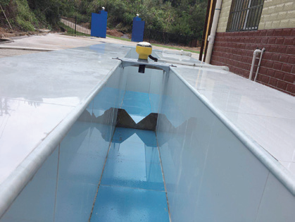
The CS-3300 series Ultrasonic Open-Channel Flow Meter is used together with a measuring weir or flume to measure the flow of water in an open channel. It is mainly used for sewage-treatment plants, the sewage-discharge outlets of enterprises and institutions, urban sewers, and irrigation channels in farmland water-conservancy projects.
It can directly display instantaneous flow and cumulative flow, with built-in EEPROM memory that retains data after a power failure. The measurement result is not affected by water quality, and multiple built-in algorithms support a wide range of standard weirs and flumes. Optional communication interfaces allow easy connection to DCS / cloud systems for remote monitoring.
The CS-3300 is available in three styles to suit different installation conditions: Integrated, Split, and Dual-Probe.
High-quality modules are selected from the power-supply stage onward, with stable, reliable components — a direct replacement for imported instruments.
Patented acoustic-wave intelligent technology performs intelligent echo analysis without debugging, with dynamic-analysis functions and strong anti-interference (level accuracy up to ±0.3% on capable models).
Non-contact measurement — the instrument does not touch the liquid, giving a low failure rate; multiple installation methods are supported.
Three styles (integrated / split / dual-probe) cover compact mounting, remote display, and small-blind-zone short-range applications.
3 Types
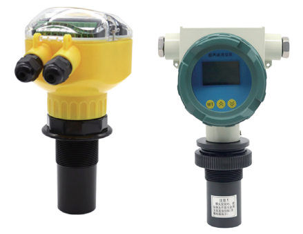
1. Integrated (CS-3300-I)
The transmitter and ultrasonic probe are built into a single unit with no probe cable. Housing options: large ABS enclosure, or explosion-proof cast-aluminum enclosure. Best for compact installations where the display can sit at the measuring point.
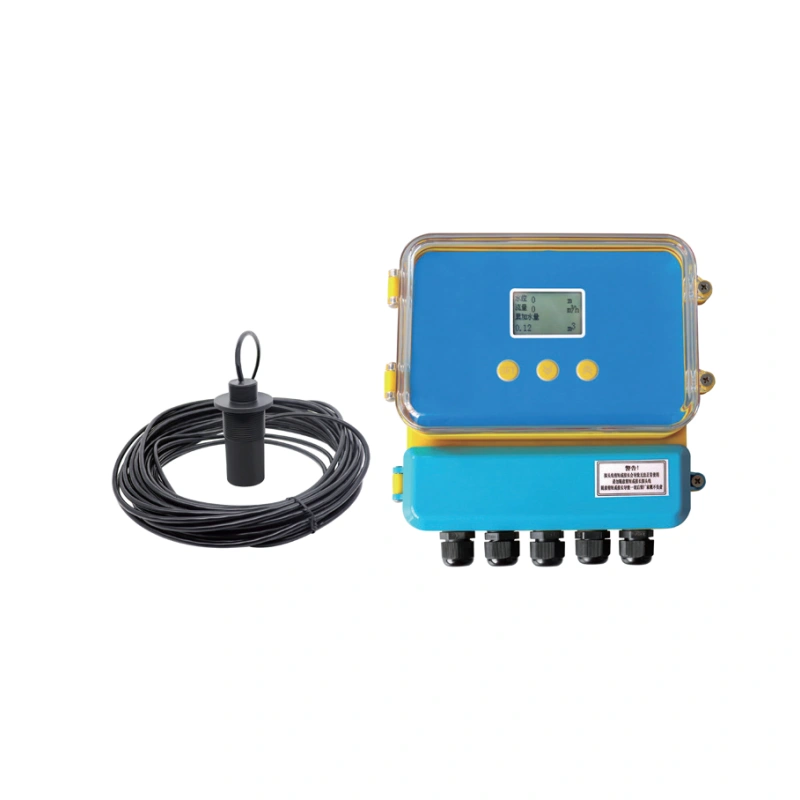
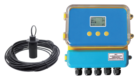
2. Split (CS-3300-S)
The transmitter and probe are separate, connected by cable (standard 10 m, customizable up to 50 m). ABS enclosure. Best when the display needs to be located away from the measuring point.
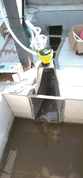
3. Dual-Probe (CS-3300-D)
Uses two 100 kHz transducers in a transmit-and-receive arrangement — one probe transmits while the other receives — achieving a very small blind zone (as low as 0.08 m). Ideal for small spaces and short-range / small-blind-zone measurement.
Technical Parameters
Parameter
Integrated
Split
Dual-Probe
Type
Integrated
Split
Dual-probe (one transmits, one receives)
Measuring principle / probe
Single ultrasonic probe; 100 kHz M48×2 for Parshall #1–9 (range 2 m, blind 13–15 cm); 64 kHz M48×2 for #10–25 (range 3 m, blind 30–40 cm)
Same as integrated
Dual 100 kHz transducers; blind zone as low as 0.08 m
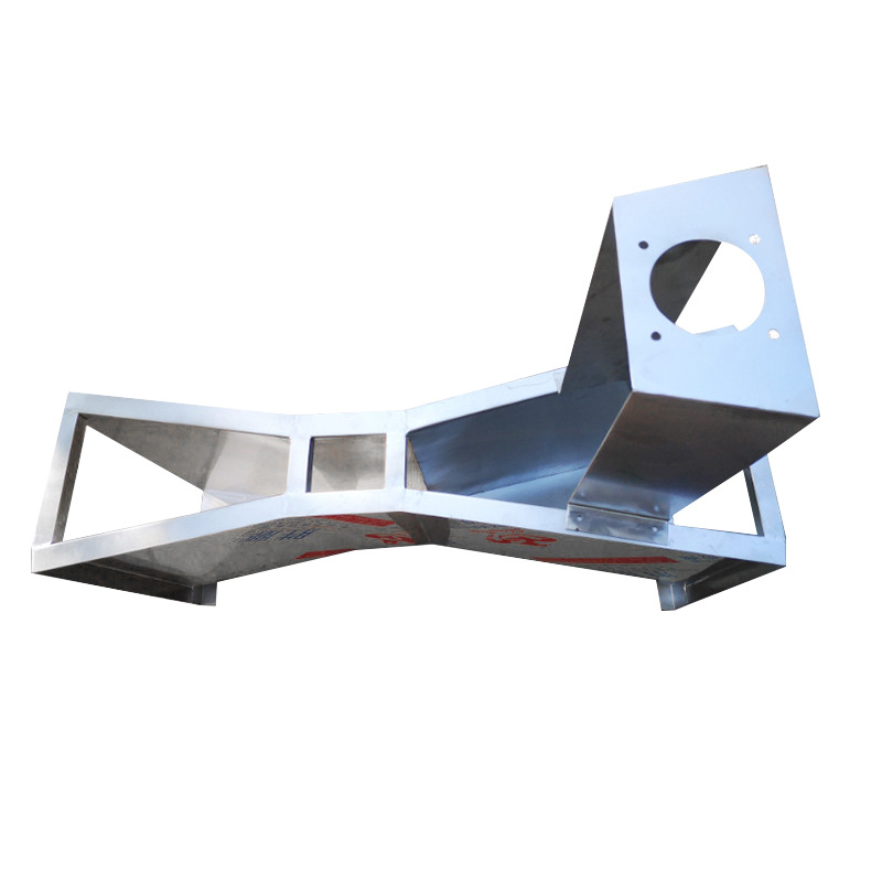
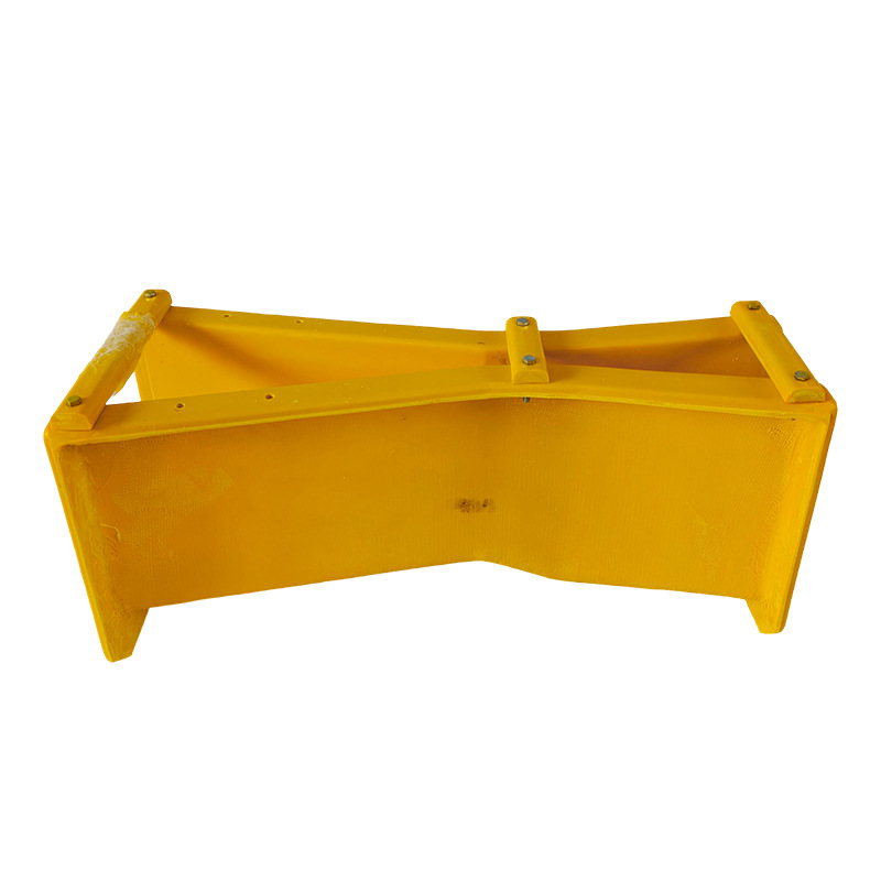
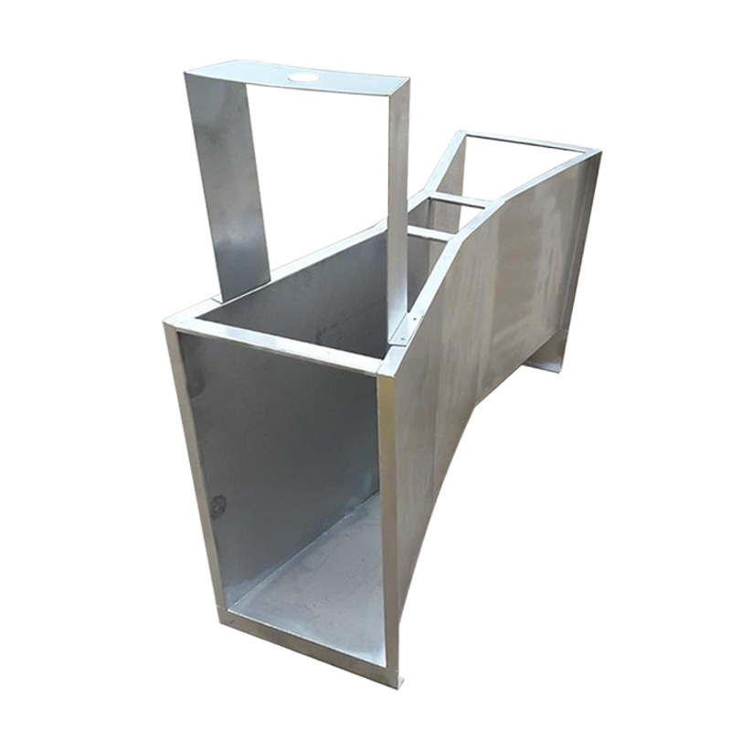
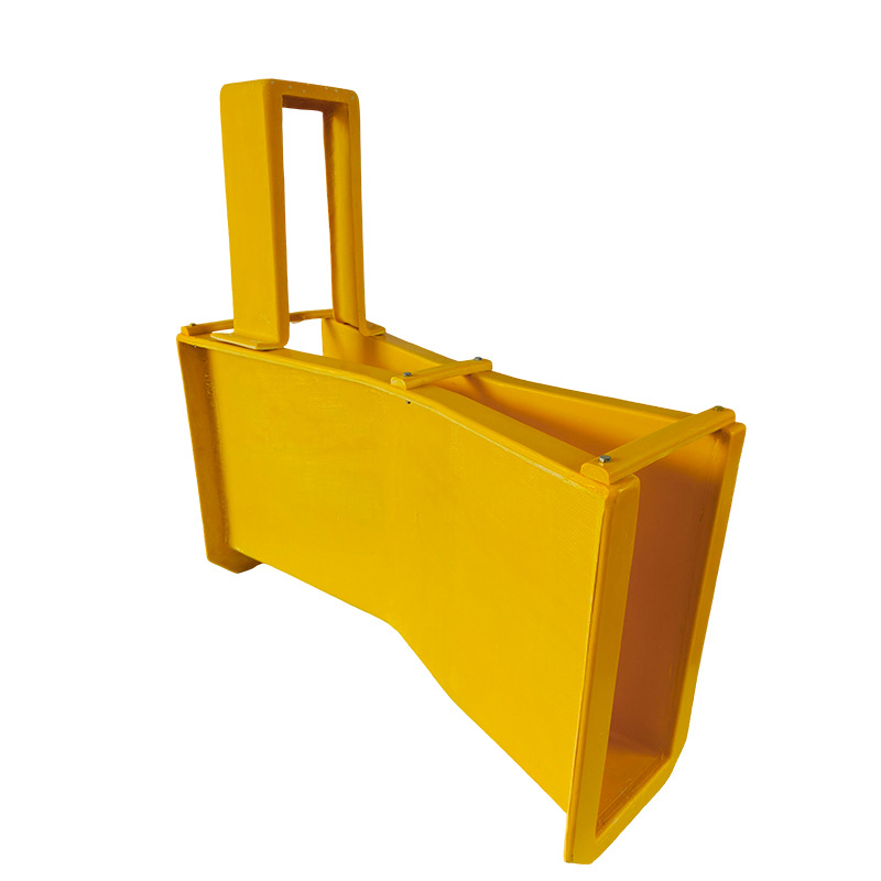
Triangular and rectangular weir grooves can be made on site according to the channel size; the Parshall flume can be produced on site by the customer or supplied as a set. Consult customer service for other weir/flume model parameters.
Ultrasonic Open-Channel Flow Meter Order Guide
Build the complete model number by choosing one option from each position below, left to right. The style is the first position.
00 = none (integrated); 01 = 1 m … 50 = 50 m (split; 10 m standard)
Example: CS-3300-S-10-A-A-A-AC-R2-C4MA-PL-10= Split style, 10 m range, ABS sensor housing, M48×2 thread, bracket mounting, 220 VAC (non-Ex) power, 2 relays, 4–20 mA + RS485 output, ABS transmitter, 10 m cable.
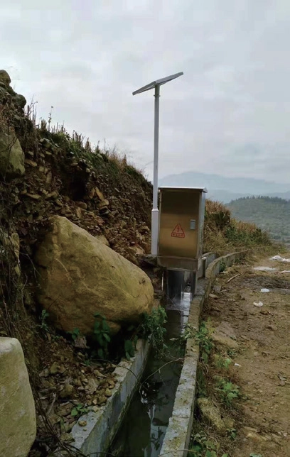
Ultrasonic Open-Channel Flow Meter Installation
1. Sensor Installation Principles
The distance from the sensor transmitting face to the lowest liquid level must be less than the range of the selected instrument.
The distance from the sensor transmitting face to the highest liquid level must be greater than the blind zone of the selected instrument.
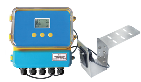
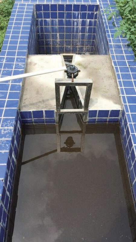
The transmitting face of the sensor must be kept parallel to the liquid surface; for triangular/rectangular weirs, mount the transducer 0.5–1 m from the weir plate at a point of steady flow.
2. Open-Channel Requirements
Open-channel width ≥ flume/tank body width.
Open-channel depth ≥ tank height. Where pedestrians or vehicles cross, channel depth ≥ groove-body height + bracket height + protruding probe part + cover-plate thickness.
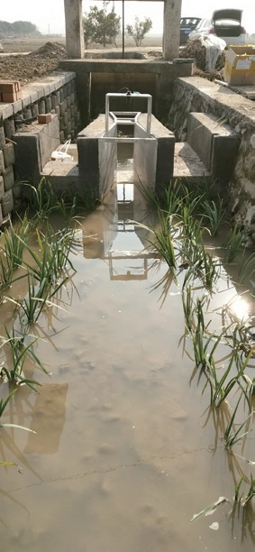
3. Parshall Flume Installation Steps
With the open channel constructed, connect the tank body and bracket using the prepared bolts.
Place the assembled flume in the channel, following the flow direction (large head in, small head out), horizontally in the middle, centerline aligned with the channel centerline; level with a spirit level.
Fix the inlet and outlet ends with baffles to allow smooth secondary (concrete) pouring.
After installation, wait until the concrete has set before installing and commissioning the instrument.
To prevent water impact, use a 45° buffer slope on both sides and the bottom; for large grooves embed steel bars in the concrete.
4. Installation Precautions & Maintenance
Place the flume horizontally (use a spirit level); its centerline must coincide with the channel centerline.
Keep the buffer (straight) section long enough for smooth, free-flow water through the contraction section.
Ensure unobstructed drainage at the outlet to avoid silting and backflow, which disturb the flume’s dynamic balance.
For special channel sizes, achieve free flow by adding a storage pool, a buffer plate, or extending the buffer straight section.
Routinely check for obstacles below the bracket and confirm upstream/downstream flow is unobstructed; downstream backflow raises the contraction-section level and makes the measured flow read too high.
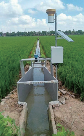
Applications of Ultrasonic Open-Channel Flow Meters
Flow monitoring for farmland irrigation;
Flow monitoring at industrial discharge outlets;
Monitoring at wastewater treatment plant outfalls;
Monitoring of wastewater discharge from livestock farms;
Monitoring of agricultural irrigation channels;
Monitoring of wastewater discharge from chemical plants;
By Li Rui, Senior Process Engineer at Sino-Inst | Published 2026-03-24. If you’ve ever had an ultrasonic level sensor fail prematurely, there’s a good chance the probe material was wrong…
When purchasing pressure transmitters or flow meters, the sales engineer will usually confirm with you what IP rating you need: IP65, IP67, or IP68? This explanation aims to help you…
Oval Gear Flow Meters are high-precision volumetric flow meters for liquids. They are used for continuous or intermittent measurement and control of liquid flow in pipelines. They are suitable for…
What are the advantages and disadvantages of vortex flowmeters? Understanding Vortex Flow Meter Advantages and Disadvantages can help us better choose the right flow meter. The vortex flowmeter is a…
Mass Flow Meter and Magnetic Flow Meter are our commonly used liquid flow meters. What Is the Difference Between a Mass Flow Meter and a Magnetic Flow Meter? When it…
The target flow meter is mainly used to solve the flow measurement of high viscosity and low Reynolds number fluid.The target flowmeter mainly has two measurement forms: the basic type…
Where should Magnetic Flow Meter Troubleshooting start? As a kind of industrial electronic sensor equipment, electromagnetic flowmeters will inevitably have some equipment failure problems in the process of use. So…
What is the turbine flow meter K factor? This question has garnered considerable attention. The K factor of a turbine flow meter is a coefficient that represents the ratio of…
Zhang Wei, possesses 20 years of experience as an automation instrumentation engineer, specializing in the research, design, installation, commissioning, and maintenance of automation instruments.
Face to various instrument communication protocols (such as Modbus, Profibus, etc.), with solid hardware circuit design and software programming skills (proficient in C language and PLC programming). Has extensive project experience; projects he has led and participated in have all achieved outstanding results, improving product accuracy, reducing costs, and increasing production efficiency.
Possesses excellent communication and coordination skills and a strong team spirit, enabling him to quickly respond to customer needs and provide high-quality automation instrumentation solutions.