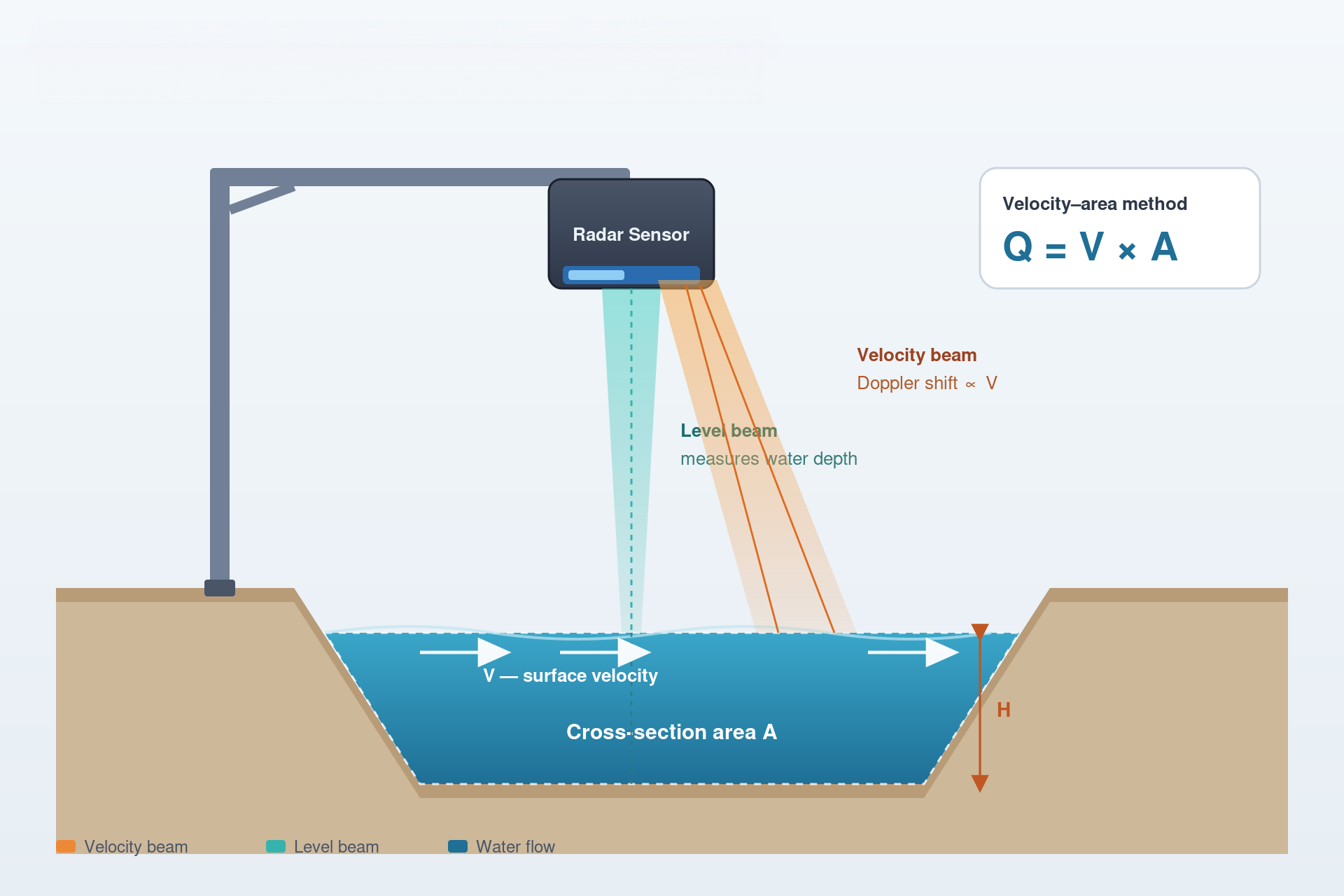
The radar flow meter is a compact, non-contact, online monitoring device designed for applications such as open channels and natural rivers. It operates based on the Doppler effect: electromagnetic waves are transmitted toward the water surface and scatter upon contact with the moving water, generating an echo. Because the frequency of the received echo shifts relative to the transmitted frequency, the surface flow velocity can be determined using the Doppler frequency equation; the flow rate is then calculated using the velocity-area method.
For weir/flume-based measurement, see the ultrasonic open channel flow meter — another open channel flow measurement solution from Sino-Inst.
The radar flow meter offers the following functions: measuring water depth and surface flow velocity; processing surface velocity data via internal algorithms to output the average flow velocity; and calculating the cross-sectional flow area based on input cross-section data.
24GHz planar microstrip radar offering non-contact measurement, safety, low power loss, minimal maintenance, and immunity to interference from silt or sediment;
IP67 waterproof design suitable for diverse outdoor settings and extreme weather conditions;
Integrated protection against reverse polarity, lightning strikes, and overvoltage;
Supports the Modbus-RTU protocol for easy system integration;
Delivers rapid, accurate measurements with stable data output, even in high-velocity flood conditions;
Flexible, adjustable antenna transmission frequency to effectively prevent mutual interference between multiple units;
Combines active measurement with sleep modes to conserve energy;
Designed to prevent internal condensation and withstand water and lightning, making it suitable for various outdoor environments;
Compact, easy to install, and simple to maintain;
Radar Flow Meter Working Principle
The radar flow meter integrates a planar radar water level sensor and a radar flow velocity sensor. The water level sensor measures the current water level, while the velocity sensor measures and calculates the average flow velocity. Based on the velocity-area method, the instantaneous flow rate of the cross-section is calculated as: Average Velocity × Cross-sectional Area × Flow Coefficient. Common open-channel cross-section shapes include rectangular, trapezoidal, and U-shaped, while drainage network sections are typically circular. Flow rate can be accurately calculated using specific formulas based on the measured water level, cross-section shape, and dimensional parameters.
Water Depth Measurement:
A radar level sensor located at the bottom of the instrument emits a signal vertically toward the water surface; by measuring the distance to the surface, the water depth is determined.
Flow Velocity Measurement:
The radar velocity meter measures the speed of moving objects using microwaves, operating on the Doppler principle. The radar emits microwaves in a fan-shaped pattern (S1), and targets on the water surface within the illuminated area reflect the microwaves (S2). The frequency difference between S2 and S1 constitutes the Doppler shift (Sd). Given a flow velocity (V), the Doppler shift (Sd) is directly proportional to the fluid velocity (V); thus, V can be calculated from Sd.
Cross-section Data Entry:
The system supports the entry of dimensional data for rectangular, trapezoidal, pipe, and irregular cross-section shapes.
Technical Specifications
Parameter
Specification
Flow Velocity
Measuring range: 0.10–25 m/s (depends on water flow conditions); Accuracy: ±0.01 m/s; Resolution: 1 mm/s
Water Level
Range: 0.1–35 m; Resolution: 1 mm; Accuracy: ±1 mm (±0.5% of measured level)
Flow Rate
Accuracy: ±2% of measured flow
Power Supply
DC 9–28 V
Operating Current
50 mA @ 12 V DC
Transmitting Frequency
Velocity: 24 GHz; Water level: 120 GHz
Antenna Type
Velocity: planar microstrip array antenna; Water level: lens antenna
Beam Angle
Velocity: 12° × 25°; Water level: 6°
Operating Temperature
−30 °C to 70 °C
Storage Temperature
−40 °C to 70 °C
Operating Humidity
≤ 95%
Output Interface
RS485 (standard MODBUS; customizable protocol; compatible with domestic and international RTUs)
Software Functions
Basic acquisition parameter setup, reading time records and historical data, etc.
Configuration Method
Bluetooth mini-program; host computer software
Communication Protocol
Modbus-RTU
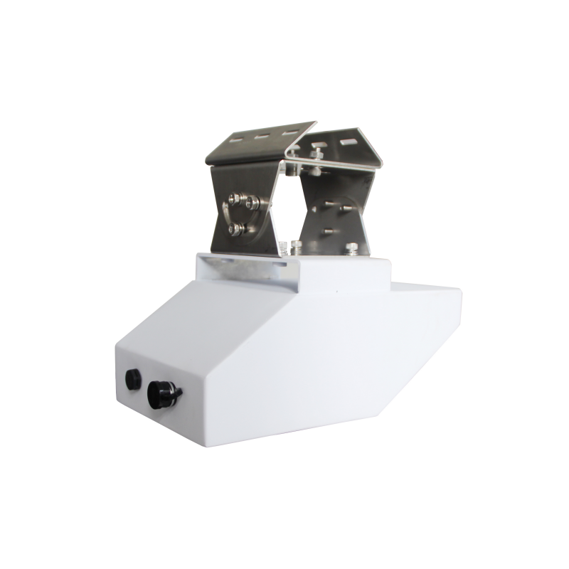
Housing Material
Aluminum alloy
Dimensions
265 mm × 151 mm × 125 mm
Protection Rating
IP67
Featured Applications
Radar flow meters are widely used in hydrological surveys, surface water resource monitoring, water volume measurement in irrigation districts, and river channel monitoring, as well as in natural water bodies and conduits such as canals, agricultural pipelines, rivers, reservoirs, lakes, tidal areas, open irrigation channels, and waterways.
They are also suitable for monitoring water levels in contexts such as urban waterlogging, municipal sewage, and municipal water intake and discharge systems, as well as for flood control and underground pipe network monitoring. Additionally, they are used for monitoring flow rates in drainage networks, discharge outlets, and ecological discharge from hydroelectric power stations, and are applicable to both regular and irregular cross-sections.
Radar flow measurement systems enable the all-weather, automatic data collection and real-time monitoring of flow rates and water body parameters in open channels and natural rivers.
Operating Conditions for Radar Flow Meters
The selection of the flow measurement channel section directly affects measurement accuracy. To ensure optimal results, the section should meet the following conditions:
① The section must be free of large obstructing boulders and devoid of phenomena such as massive eddies or turbulent flow; ② The section should ideally be straight and stable, with concentrated flow; ③ The section requires surface hardening, and the measurement cross-section should be uniform and regular; ④ The section must remain unobstructed to prevent the accumulation of floating debris.
Installation
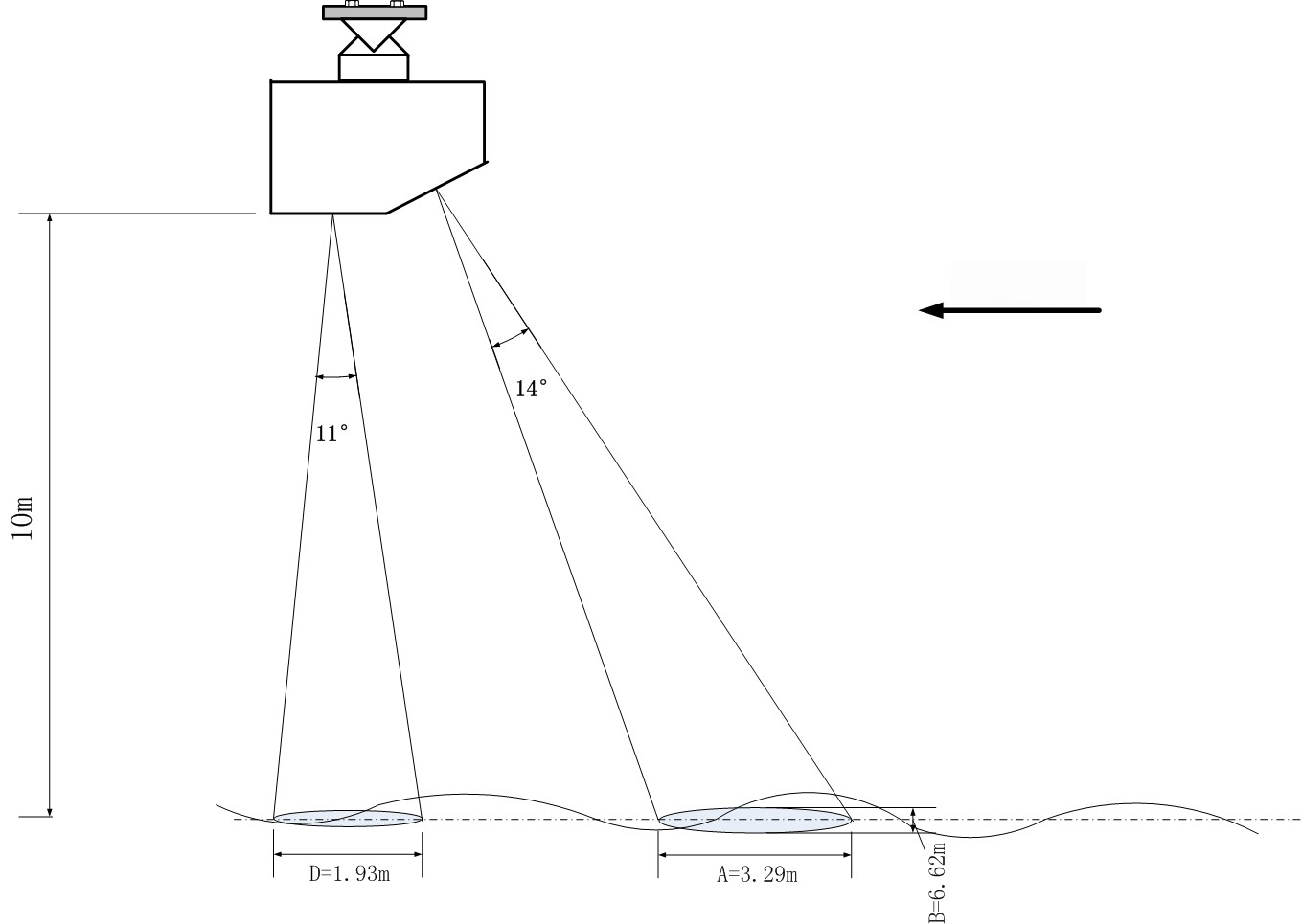
1. Installation Angle
The radar water level meter has an antenna beam angle of 6°, while the radar flow velocity meter has an antenna angle of 12° × 25°. When the water level meter illuminates the water surface, the illuminated area is roughly circular; when the radar flow velocity meter illuminates the water surface, the illuminated area is roughly elliptical, as shown in the figure above.
Prior to installation, select an appropriate mounting angle to ensure the beam illuminates a section of steady water flow. The dimensions of the illuminated area on the water surface are directly proportional to the mounting height. The table below lists the parameter values (A, B, and D—refer to the figure above for definitions) for a mounting height of 1 meter; the actual parameter values are obtained by multiplying these listed values by the actual mounting height (in meters).
Name
Length (m)
Flow Meter A
0.329
Flow Meter B
0.662
Water Level Meter Diameter D
0.052~0.192
Parameter values for the antenna beam illumination area
2. Installation Height
The theoretical installation height for the flow meter is up to 20 meters. Under identical conditions, a greater installation height results in a weaker echo and poorer signal quality; detection becomes particularly difficult in scenarios with low flow velocities and minimal surface ripples.
Additionally, a higher installation height increases the area illuminated by the radar beam. The beam may strike the channel banks, making the measurement susceptible to interference from moving objects on the banks. Whenever possible, the device should be installed at a height of 10 meters or less; please determine the installation height based on actual site conditions.
3. Installation Precautions
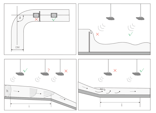
When installing the flow meter, position the antenna to face upstream (i.e., against the flow). The displayed flow velocity will be positive. Avoid the following situations during installation:
Ensure there are no obstructions between the flow meter (specifically the water level and velocity radar units) and the water surface, as this would compromise measurement accuracy;
Ensure the top surface of the housing is as level as possible and mount the unit in the center of the channel;
The velocity radar responds only to moving targets; if the channel is lined (hardened) and free of weeds or trees, the measurement will not be affected even if the radar beam strikes the channel sidewalls;
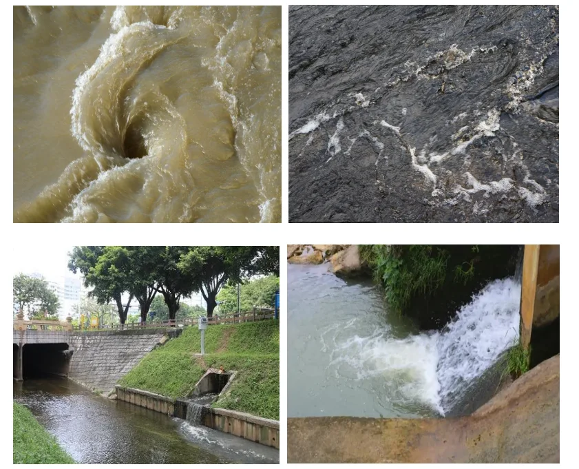
Avoid installing the velocity radar near river eddies, areas with complex flow patterns, pipe outlets, rapid flow discharge points, steep weirs/rapids, or sluice gates.
Examples of improper installation locations are shown in the figure below:
Radar flow meters utilize proven radar-based water level and velocity measurement technologies; they are primarily used to measure water levels and flow velocities in open channels, such as rivers, reservoir sluice gates, underground conduit networks, and irrigation canals.
Sino-Inst offers professional flow measurement solutions for open channels and non-full pipes. In addition to radar flow meters, our product range includes ultrasonic open-channel flow meters and non-full pipe flow meters. Please feel free to contact our sales engineers for technical support.
The ability to measure flow rates externally without the need for penetration of the fluid-carrying pipe is a boon in modern-day Industrial processes. That’s why, Non-invasive, Non-intrusive flow meters is…
After a period of use, electromagnetic flow meters may experience a decrease in accuracy. Magnetic flow meter calibration eliminates systematic errors inherent in the instrument, ensuring the reliability of its…
Nitrogen Flow Controllers are devices specifically designed for measuring and controlling nitrogen flow. They not only measure the volumetric or mass flow rate of nitrogen, but crucially, they also control…
By Li Rui, Senior Process Engineer at Sino-Inst | Published 2026-03-24. If you’ve ever had an ultrasonic level sensor fail prematurely, there’s a good chance the probe material was wrong…
Powder/Dry Material Level Switches are devices used to detect when material reaches a preset level. When the material reaches or exceeds the set position, the level switch sends a signal,…
When it comes to flow measurement, understanding the distinction between mass flow rate and volumetric flow rate is crucial. Both concepts are widely used in various industries, but they differ…
Zhang Wei, possesses 20 years of experience as an automation instrumentation engineer, specializing in the research, design, installation, commissioning, and maintenance of automation instruments.
Face to various instrument communication protocols (such as Modbus, Profibus, etc.), with solid hardware circuit design and software programming skills (proficient in C language and PLC programming). Has extensive project experience; projects he has led and participated in have all achieved outstanding results, improving product accuracy, reducing costs, and increasing production efficiency.
Possesses excellent communication and coordination skills and a strong team spirit, enabling him to quickly respond to customer needs and provide high-quality automation instrumentation solutions.