Home > Blog > Magnetic Flow Meter Calibration Procedure – User Guide
Magnetic Flow Meter Calibration Procedure – User Guide
After a period of use, electromagnetic flow meters may experience a decrease in accuracy. Magnetic flow meter calibration eliminates systematic errors inherent in the instrument, ensuring the reliability of its measurement results. This meets the needs of process control, cost accounting, and trade settlement.
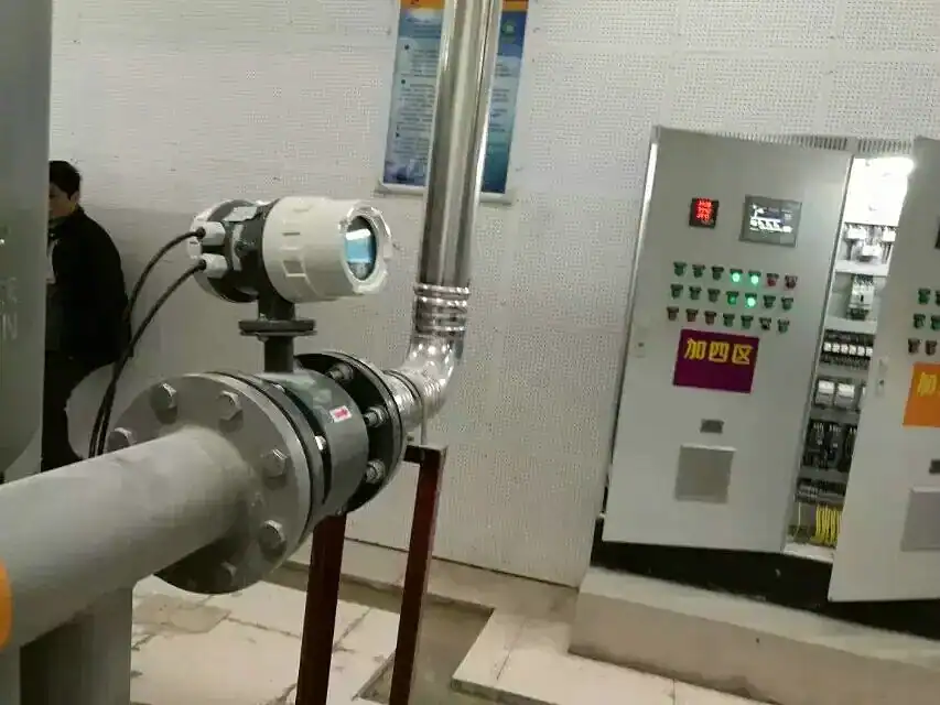
Electromagnetic flow meters are suitable for measuring the flow rate of conductive liquids in closed pipelines and are widely used in various industries such as chemical engineering, wastewater treatment, agricultural irrigation, and urban water management. Therefore, electromagnetic flow meter calibration is a crucial issue for users. In fact, the calibration cycle and implementation process should be considered before purchasing.
Calibration is the process of comparing and correcting the instrument’s output value to bring it closer to the “true value,” focusing on improving accuracy. Typically, we calibrate the flow meter in-house before shipment and provide a calibration report. Users can then perform periodic calibrations according to their needs.
Verification is a conformity assessment conducted by a legally authorized body according to regulations, focusing on legal compliance. For example, if you purchase an electromagnetic flow meter with an accuracy of 0.5%FS, you can submit it to a third-party organization for testing and obtain a flow rate test report to verify whether the 0.5% accuracy is accurate.
The Importance of Electromagnetic Flowmeter Calibration
Ensure the measurement accuracy of electromagnetic flowmeters. Electromagnetic flowmeters are crucial in water treatment, chemical engineering, and various manufacturing industries. Ensuring their accuracy guarantees the accurate measurement of liquid consumption and output.
Save costs and improve efficiency. Measurement errors are not directly visible to the naked eye, but after calculation, they can represent significant economic costs. Accurate flow monitoring provides accurate analytical data, preventing raw material waste, optimizing production processes, and saving costs.
Comply with industry standards and regulations. Various industries have their own industry standards and quality management systems (ISO 9001), all of which require accuracy in flow measurement and regular calibration.
Extend the lifespan of electromagnetic flowmeters. Regularly calibrating flowmeters stabilizes measurement accuracy and prevents malfunctions.
Electromagnetic Flowmeter Calibration Cycle
Calibration Cycle: The verification procedure JJG 198-94, “Verification Procedure for Velocity Flowmeters,” stipulates that the calibration cycle for flowmeters with an accuracy class of 0.1, 0.2, and 0.5 is six months. For electromagnetic flowmeters with an accuracy class lower than 0.5, the calibration cycle is generally specified as two years, although longer cycles are also possible.
Furthermore, in some practical applications, strictly adhering to the procedures is very difficult. For example, large-diameter electromagnetic flowmeters are difficult to install and disassemble, making actual flow calibration difficult to achieve during periodic calibration. Online periodic verification and inspection are often used instead.
Magnetic Flow Meter Calibration Procedure
Select the appropriate water pump based on the pipe diameter and flow rate for the calibration test.
If the system uses compressed air power, turn on the air compressor to reach the required air source pressure to ensure rapid switching of the commutator and normal operation of the clamp meter.
After the electromagnetic flowmeter is correctly installed and connected, it should be preheated for approximately 30 minutes.
If using a high-level water tank, check if the overflow signal of the pressure stabilizing tower appears. Before the formal test, circulate the calibration medium in the pipeline system for a certain period of time, while checking for leaks at all sealing points in the pipeline.
Before starting the formal calibration, fill the sensor of the flowmeter under test with the calibration medium, then close the downstream valve for zero-point adjustment.
At the start of the calibration, first open the valve at the front end of the pipeline, then slowly open the valve after the flowmeter under test to adjust the flow rate at the calibration point.
During the calibration process, the flow rate stability at each flow point should be within 1% to 2%—for the flow rate method, while for the total flow rate method, it can be within 5%.
The temperature change of the test medium should not exceed 1°C during the calibration process at a single flow point, and should not exceed 5°C during the entire calibration process.
The downstream pressure of the flowmeter under test should be sufficiently high to prevent flashing and cavitation within the flow path (especially in narrow-bore sections).
Each measurement should last at least the minimum allowable measurement time of the device, generally not less than 30 seconds. For Class A instruments (referring to electromagnetic flowmeters with frequency output, and insertion-type electromagnetic flowmeters with frequency output), the absolute relative error of the number of pulses output by the flowmeter in a single calibration should not exceed 1/3 of the repeatability of the flowmeter under test.
Each calibration point should be calibrated at least three times. For Class 0.1 and 0.2 flowmeters, each calibration point should be calibrated at least six times.
After each test, the valve at the front end of the test pipeline should be closed first, then the pump should be stopped to prevent the pressure stabilizing equipment from being emptied. Simultaneously, all remaining test medium in the test pipeline must be vented, and finally, the control system and air compressor should be shut down.
The calibration points for evaluating instrument performance are generally specified as follows:
For Class A instruments, referring to electromagnetic flowmeters with frequency output, and insertion-type electromagnetic flowmeters with frequency output, calibration points should include qmin, 0.07qmax, 0.15qmax, 0.25qmax, 0.4qmax, 0.7qmax, and qmax. When the flow rate at the latter few calibration points is less than qmin, this calibration point can be disregarded.
For Class B instruments, referring to electromagnetic flowmeters that output analog signals or can directly display instantaneous flow, calibration points should include at least 5 verification points, including qmin and qmax, and should be evenly distributed.
For calibrations not used to evaluate instrument performance (such as factory calibration), fewer calibration points may be specified.
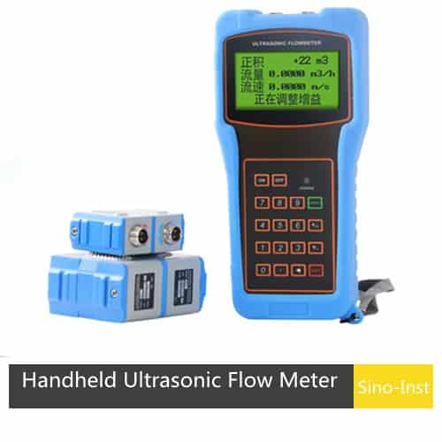
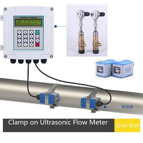
Calibration of Electromagnetic Flowmeters with Clamp-on Ultrasonic Flowmeters
The accuracy of electromagnetic flowmeters is generally 1.0%, 0.5%, or 0.2%, while that of ultrasonic flowmeters is 1.0% or 0.5%. According to the calibration procedures for velocity flowmeters, the error of the testing device must be smaller than that of the electromagnetic flowmeter, which obviously does not meet the requirements for online calibration of electromagnetic flowmeters.
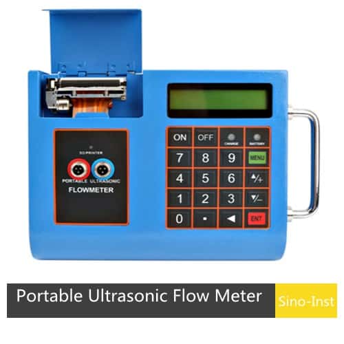
However, this is quite common in practical applications. This is because the disassembly, transportation, delivery, and installation costs of large-diameter electromagnetic flowmeters are significant. Furthermore, some process pipelines require continuous production and cannot be shut down. Therefore, using clamp-on ultrasonic flowmeters for inspection and calibration remains feasible and meaningful. This is because errors caused by metering disputes, electrode scaling, or converter malfunctions are generally much larger than 0.5% or 1.0%.
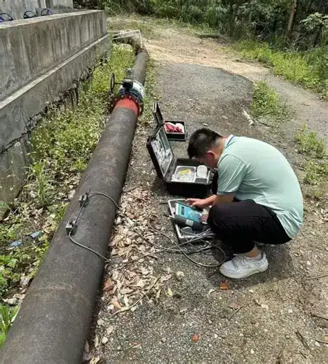
For example, one of our clients, a water supply company, previously installed a DN1200 in-line electromagnetic flowmeter, with most of the measured pipeline underground. In this case, only clamp-on ultrasonic flowmeters could be used, purchased using a “V”-type installation method, with two probes installed at the top of the pipeline for measurement.
Our instantaneous measurement was 3190 m³/h, while the electromagnetic flowmeter’s measurement was 3183 m³/h. Over a period of time, the two measurements consistently differed by approximately 6-7 m³/h. The cumulative values over that period were: ultrasonic flowmeter 532 m³/h, electromagnetic flowmeter 530 m³/h, with an error of 0.375%.
The larger the pipe diameter, the greater the time difference Δt between the forward and reverse flow, allowing for more precise measurement of the time difference and thus more accurate flow rate measurement. Therefore, using a high-precision ultrasonic flowmeter for on-site calibration of the electromagnetic flowmeter is feasible.
FAQ
The measurement accuracy of an electromagnetic flow meter is affected by many factors. Based on our years of experience resolving user questions related to electromagnetic flow meters, we have summarized the following 10 points. When your electromagnetic flow meter is malfunctioning, you can check each one.
Medium Factors: If the medium contains air bubbles or non-conductive substances, it will affect the uniformity of the magnetic field, leading to measurement errors. For example, in wastewater treatment, air bubbles in the water may cause the flow meter to misjudge the flow rate.
Installation Issues: Improper pipe installation, such as a mismatch between the pipe’s inner diameter and the flow meter, or the presence of bends, will cause turbulent fluid flow, affecting measurement accuracy.
Electrode Failure: Dirt or corrosion on the electrode surface will hinder current conduction, resulting in inaccurate measurement signals.
Excitation Issues: A faulty excitation coil or an unstable excitation frequency will prevent the generation of a stable magnetic field, thus affecting the measurement results.
Pipeline Vibration: Pipeline vibration can cause slight displacements in the measuring tube and electrodes of the electromagnetic flowmeter, leading to changes in the induced electromotive force and introducing measurement errors.
External Electromagnetic Interference: The presence of strong electromagnetic fields or other interference sources nearby can interfere with the flowmeter’s signal transmission and processing, resulting in inaccurate measurements. Investigating these causes helps improve the measurement accuracy of the electromagnetic flowmeter.
Instrument Aging and Wear: With prolonged use, the electrodes, lining, coil, and other components of the electromagnetic flowmeter will experience aging and wear. Scale and oxidation may form on the electrode surface, the lining may thin and crack, and the insulation performance of the coil may decrease, all of which affect measurement accuracy.
Zero Drift: Electromagnetic flowmeters may experience zero drift during measurement, meaning the instrument still outputs a signal even when there is no fluid flow.
Ambient Temperature: In high-temperature environments, the coil resistance of the electromagnetic flowmeter increases, causing changes in the magnetic field strength. Simultaneously, the fluid viscosity may decrease, and the flow velocity distribution may change, all of which affect the measurement results.
Ambient humidity: In damp underground pipes or coastal areas, the electronic circuit board of the electromagnetic flowmeter may experience short circuits, leakage, and other problems due to moisture, leading to a decrease in measurement accuracy.
The zero point of an electromagnetic flowmeter can be calibrated manually or via HART/RS485 communication.
Manual Zero Point Calibration
Steps:
Enter the converter menu and select “Zero Adjustment” or “Zero Point Calibration”.
Ensure the fluid is completely still (valve closed, no flow), and wait for the displayed value to stabilize (approximately 1-2 minutes).
Perform zero point calibration (press “Execute” or “Confirm”).
Observe whether the displayed value returns to zero (a deviation within ±0.5% FS is allowed).
Note:
If zero point drift is severe, check for electrode contamination, grounding, or electromagnetic interference.
Some instruments require a password to access advanced settings (refer to the instruction manual).
Calibration via HART/RS485 Communication
Steps:
Connect the HART handheld communicator and select “Device Setup” → “Calibration” → “Zero Trim”.
Confirm no flow, perform zero point calibration, and save.
Brewery flow meters are specialized devices that are used to measure the flow rate of liquids, such as beer and wine, in a brewery or winery setting. These devices can be used to monitor the production process, ensure quality control,…
Ultrasonic vs Magnetic Flow Meter, are you confused about which one to choose? Sino-Inst, based on our years of experience in flow measurement services, has compiled this blog, hoping to help you! Ultrasonic flow meters and electromagnetic flow meters are…
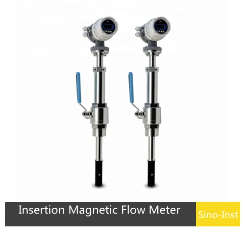
Insertion Magnetic Flow Meters are configured for use with conductive liquids in DN100~DN3000 (4″ ~ 120″) pipe. A selection of materials (stainless steel, brass, and PVC) allows the meter to adjust to a range of temperatures, pressures, and corrosive environments…
One of the bear-sized challenges in flow measurement is electromagnetic interference (EMI), which can misrepresent readings, compromise accuracy, and lead to costly functional inefficiencies. To extenuate this issue, engineers have developed electromagnetic interference resistant flow meters—specialized instruments designed to operate…
Mass flow meters quantify the fluid’s mass to ascertain the flow rate, whereas magnetic flow meters utilize magnetic fields to gauge the flow of conductive fluids. Selecting between a mass flow meter and a magnetic flow meter depends on your…
There are a few areas where industrial flow measurement is important, such as residential waste. Among the various flow meter types available, inductive flow meters, particularly magnetic inductive flow meters, are widely preferred in applications involving conductive liquids. Inductive flow…
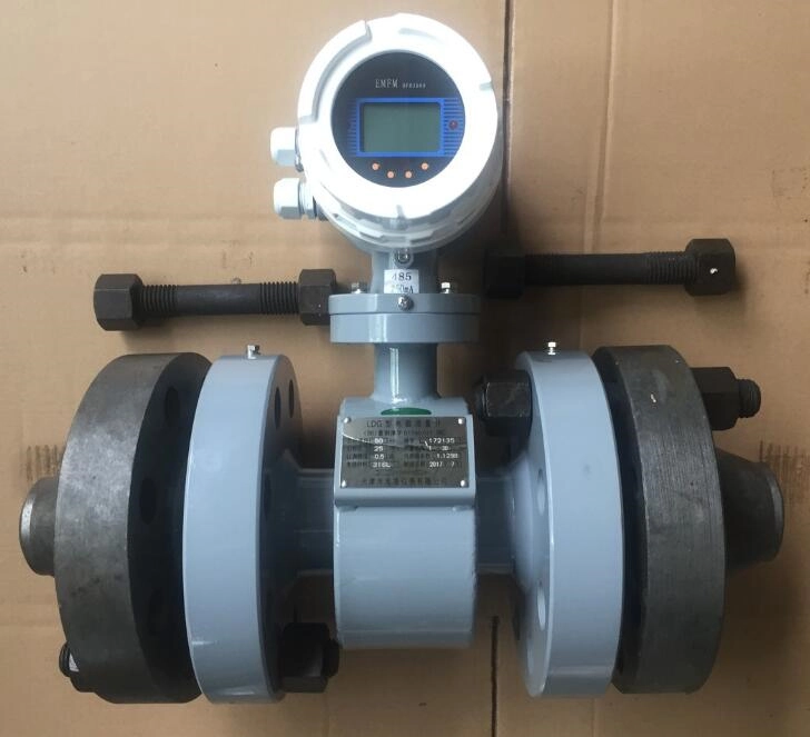
Electromagnetic flowmeter is suitable for volume flow measurement of various conductive liquid media. The only media contact parts are the electrode and the lining of the measuring tube. According to the characteristics of different media, select the Magnetic Flow Meter…
Bidirectional Flow Meters can simultaneously measure the flow of liquid or gas in both positive and negative directions. Bidirectional flow, a process in which the conveying and control functions use the same pipeline to facilitate bidirectional flow, is a critical…
Magnetic flow meter calibration is crucial for ensuring the accuracy and consistency of measurement results. Therefore, all users should perform magnetic flow meter calibration regularly to guarantee the normal operation of the flow meter.
Our Sino-Inst electromagnetic flow meters undergo factory calibration before shipment, and a calibration report is provided. We also provide technical support for users encountering calibration problems during use. Please feel free to contact us at any time.
Zhang Wei, possesses 20 years of experience as an automation instrumentation engineer, specializing in the research, design, installation, commissioning, and maintenance of automation instruments.
Face to various instrument communication protocols (such as Modbus, Profibus, etc.), with solid hardware circuit design and software programming skills (proficient in C language and PLC programming). Has extensive project experience; projects he has led and participated in have all achieved outstanding results, improving product accuracy, reducing costs, and increasing production efficiency.
Possesses excellent communication and coordination skills and a strong team spirit, enabling him to quickly respond to customer needs and provide high-quality automation instrumentation solutions.