
The Impact of Medium Viscosity on Oval Gear Flowmeters
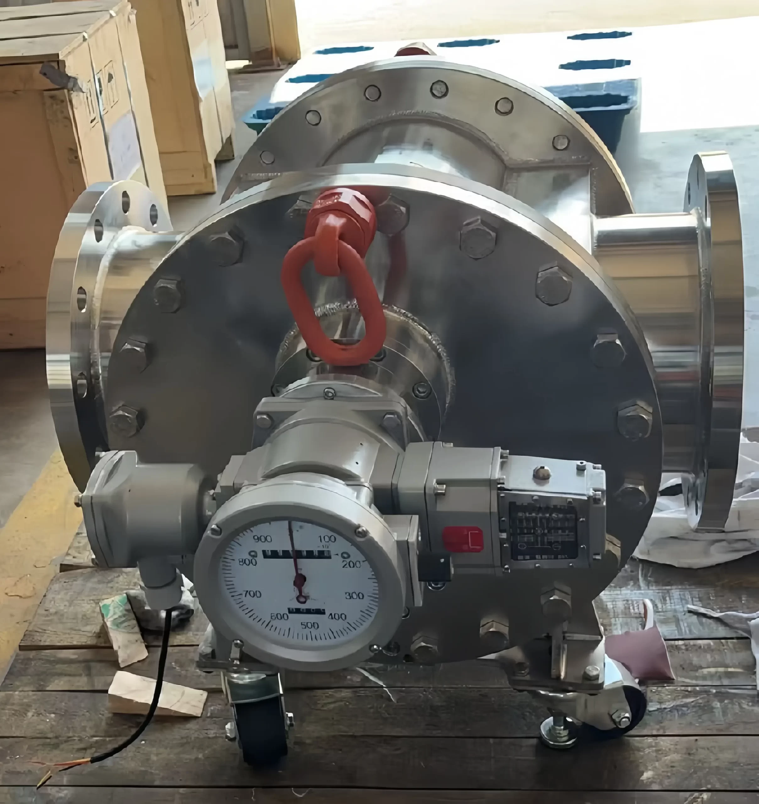
We previously received an inquiry from a user in Mexico requesting a selection recommendation and a quote for an oval gear flowmeter (a type of positive displacement flowmeter). The application involved a DN100 pipe with a flow range of 150–2500 L/min, requiring an accuracy of ±0.2% and repeatability of ≤0.05%. The client had initially selected an oval gear flowmeter himself; however, upon further discussion, he clarified that the medium was “clean water,” with a maximum pressure of 40 bar and a maximum temperature of 80°C. Given that the medium was water, we recommended an electromagnetic flowmeter or a mechanical metal-tube rotameter instead.
Why is this? The viscosity of water is only about 1 mPa·s. At this level, leakage through the gaps between the gears and the metering chamber becomes significant; the nominal accuracy of ±0.2% is only achievable when measuring oil (typically with a viscosity of 3–5 mPa·s or higher).
The specification sheet the client had obtained was likely based on a template intended for oil-service flowmeters. The client ultimately accepted a revised accuracy specification of 0.5%. This goes to show that a stated accuracy of “0.2%” may sometimes be nothing more than a figure on a datasheet—it is essential to always verify the specific medium with the manufacturer.
While it is well known that oval gear flowmeters are the preferred choice for measuring oil and high-viscosity liquids, the influence of fluid viscosity on their performance is often overlooked. When selecting a flowmeter for a user, the first step is to confirm the type, viscosity, and temperature of the medium. Therefore, verifying viscosity is crucial when selecting an oval gear flowmeter. Let’s take a closer look.
The Relationship Between Viscosity and the Meter Factor of an Oval Gear Flowmeter
An oval gear flowmeter is a type of positive displacement flowmeter. Its operating principle is as follows:
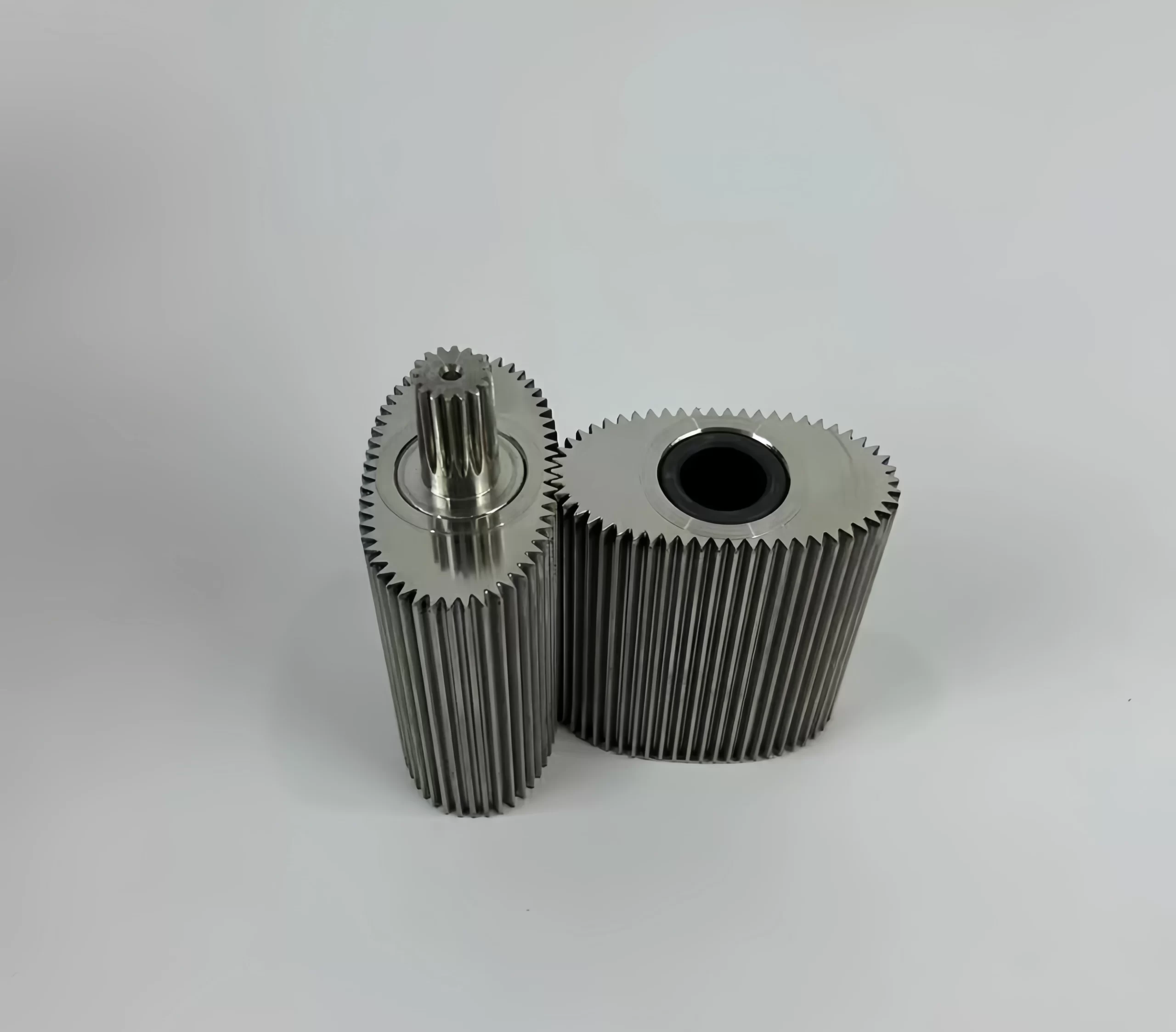
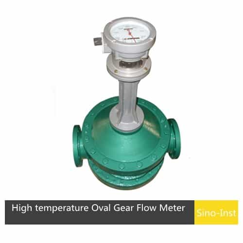
An oval gear flowmeter consists of a flow transmitter and a counting mechanism. By incorporating a heat sink between the transmitter and the counting mechanism, the device can be configured as a high-temperature model. The flowmeter consists of a metering chamber—containing a pair of elliptical gear rotors—and a sealed coupling. The counting mechanism comprises a reduction gear train, an adjustment mechanism, a counter, and a signal transmitter.
Within the metering chamber, a pair of elliptical gears and the cover plate form a crescent-shaped cavity, which serves as the unit for flow measurement. Driven by the pressure differential between the flowmeter’s inlet and outlet, the elliptical gears rotate, continuously metering the liquid as it passes through the crescent-shaped cavity toward the outlet. Each full rotation of the gears displaces a volume of liquid equal to four times the volume of the crescent-shaped cavity. A sealed coupling transmits the total number of rotations and the rotational speed of the elliptical gears to the counting mechanism or signal transmitter, thereby allowing for the determination of both the total volume of liquid that has passed through the pipeline and the instantaneous flow rate.
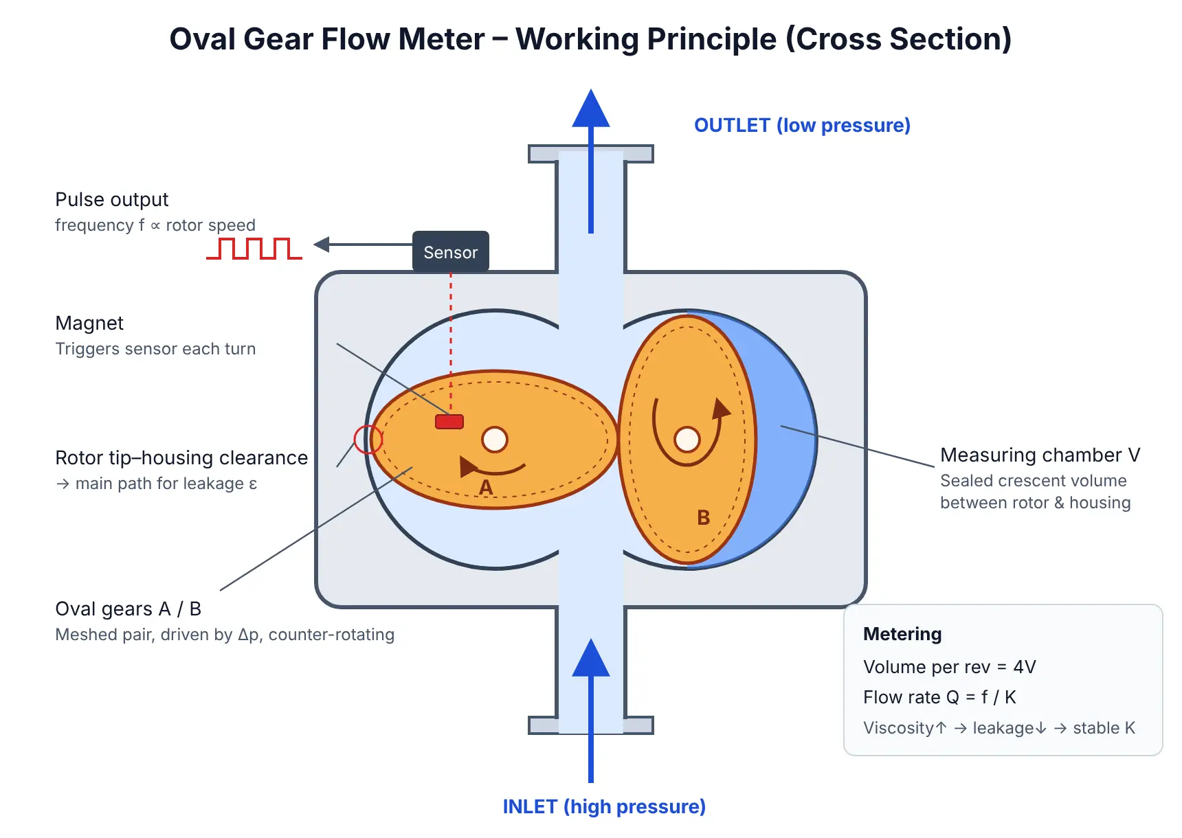
The flow calculation formula commonly used for oval gear flowmeters is the same as that for turbine flowmeters; in practical application, the flow rate is determined based on frequency and the meter factor.
Compared to turbine flowmeters, the meter factor of an oval gear flowmeter is influenced by fewer factors, with leakage being the primary one. Once the structural dimensions are fixed, the leakage can be approximately expressed as:
ε = α·Q + β·Q²/υ
Here, Q is the volumetric flow rate (L/s), α and β are constants related to the structural dimensions, and υ is the viscosity of the medium. Consequently, a higher viscosity results in less leakage, a larger meter factor, and a broader linear operating range.
In other words, the measurement accuracy of an oval gear flowmeter is directly related to the viscosity of the measured medium. As the viscosity of a fluid mixture increases, leakage through the gear clearances decreases, leading to a reduction in measurement error and an improvement in accuracy. Conversely, a decrease in viscosity may lead to increased leakage and greater measurement error.
The Effect of Low Viscosity on Oval Gear Flowmeters
The design of an oval gear flowmeter inherently includes a clearance between the gears and the housing. Due to the pressure differential between the inlet and outlet, a portion of the fluid inevitably leaks through this gap without driving the gears. Since this fluid passes through the meter without being registered, the resulting reading is lower than the actual flow. In the industry, this phenomenon is referred to as “slip” or “internal leakage.” It consistently leads to a negative measurement error—that is, an undercount.
The volume of leakage depends primarily on the fluid’s viscosity and the size of the clearance; lower viscosity results in higher leakage. Furthermore, the leakage does not decrease proportionally with the flow rate; as the flow rate drops, the leaked portion accounts for a larger percentage of the total flow. Consequently, when measuring low-viscosity media, errors typically manifest first at the lower end of the flow range.
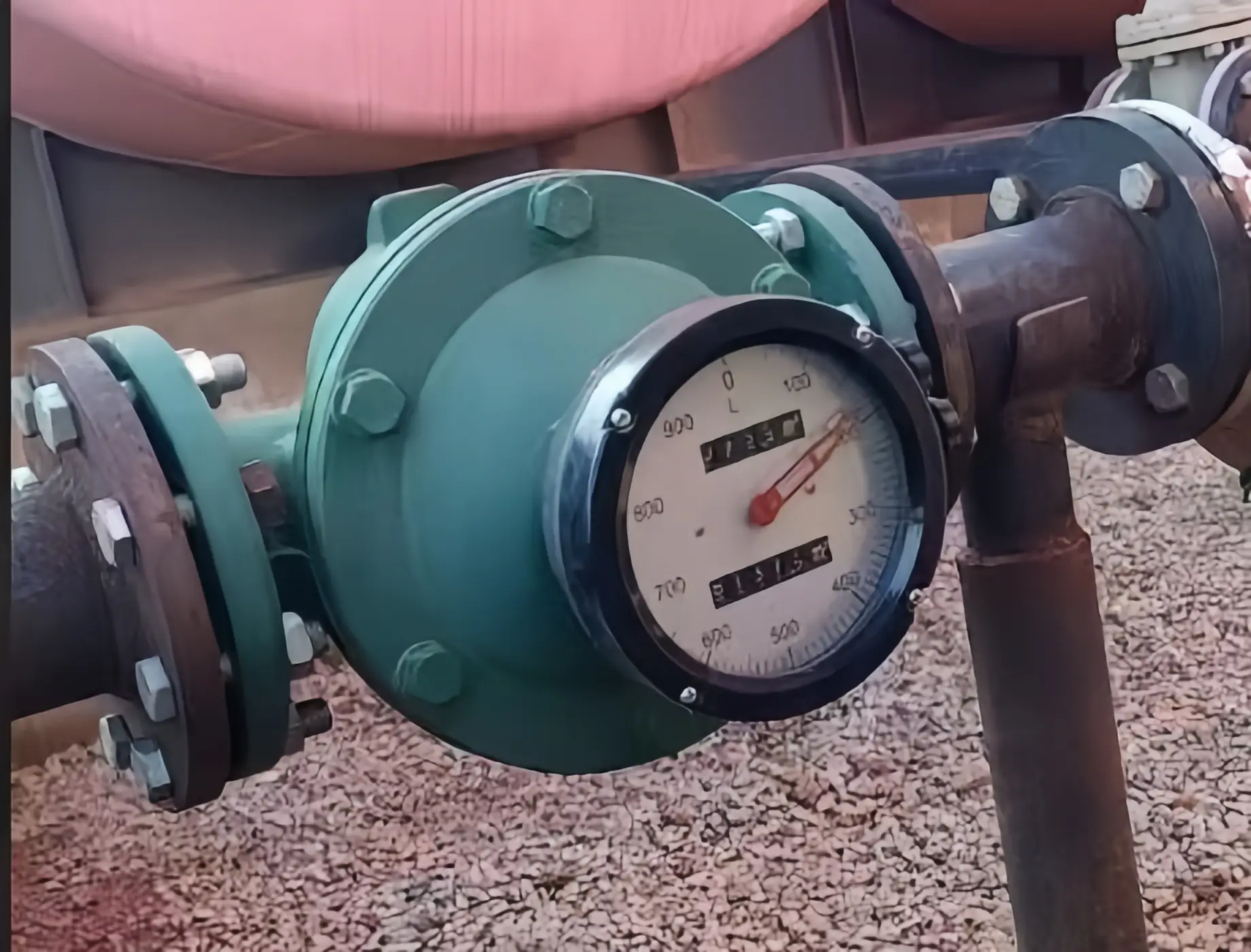
A company in New Zealand consulted us regarding a DN15 oval gear flowmeter for measuring Marine Gas Oil (MGO) under the following operating conditions:
Viscosity: 1.5–6.0 cSt at 40°C (typically around 3 cSt)
Flow rate: 0.15–1.5 m³/h
Pressure: 1.6 MPa; Temperature: -20 to 110°C
Requirement: Local display only
We selected a model based on the 0.15–1.5 m³/h range, with an accuracy of ±0.5%. For an oval gear meter, 3 cSt is considered quite low viscosity, and the ±0.5% accuracy is only valid when the fluid viscosity is close to the calibration viscosity. Given that the client’s specified viscosity range spans a factor of four (from 6 cSt down to 1.5 cSt), the leakage through the clearance will also increase roughly fourfold, leading to significant undercounting at lower flow rates. Although the client indicated that a range of 0.03–6 m³/h would also be acceptable, we did not opt for a smaller meter size to accommodate this lower limit, as the leakage would represent such a large proportion of the flow at 0.03 m³/h that the readings would be unreliable.
The Impact of High Viscosity on Oval Gear Flowmeters
When viscosity is high, leakage through the clearances between the gears of an oval gear flowmeter decreases, which actually improves measurement accuracy at low flow rates. For oval gear flowmeters, fluids with viscosities ranging from several hundred to several thousand cP are relatively easy to measure. The challenges associated with high-viscosity applications do not concern accuracy, but rather stem from three specific issues caused by the high viscosity:
- Pressure Drop. Higher viscosity leads to a greater pressure differential across the gears. Since high-viscosity fluids typically exhibit laminar flow within the meter, the pressure drop increases roughly in proportion to the viscosity. Given a constant pump discharge pressure, a larger pressure drop across the meter leaves less pressure available for the rest of the pipeline; in extreme cases, this can prevent the pump from delivering the required flow rate.
- Maximum Flow Rate. When measuring high-viscosity fluids, the maximum measurable flow rate of an oval gear flowmeter decreases. Consequently, it is often necessary to select a meter with a larger nominal diameter (one size up).
- Temperature. The viscosity of high-viscosity fluids is highly sensitive to temperature. A fluid that can be measured effectively at operating temperature may become so thick upon cooling that it prevents the gears from turning—or even solidifies entirely—causing the meter to seize.
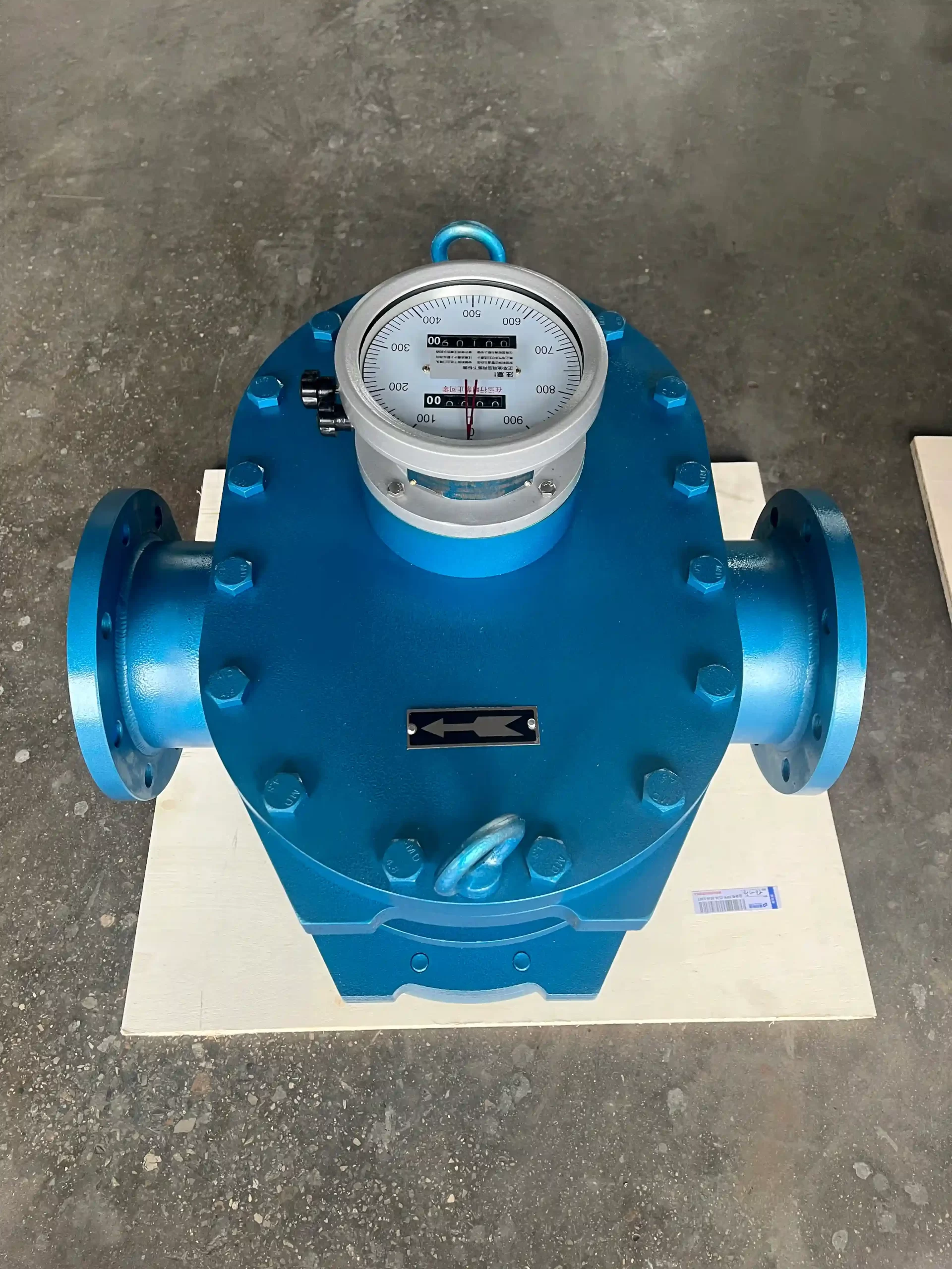
A South African equipment company once inquired about an oval gear flowmeter for an asphalt pipeline, with the following operating conditions:
Viscosity: 2000 cP
Pipe Diameter: 50NB / 80NB
Flow Rate: 80–200 L/min
Pressure: 0–6 bar
Maximum Temperature: 180°C
Output: 4–20 mA, with a digital display
A viscosity of 2000 cP has no impact on the accuracy of an oval gear flowmeter; however, we focused our assessment on two key factors:
First, heat tracing. Before providing a quote, we verified whether the client’s site was equipped with thermal oil or steam heat tracing. Asphalt solidifies upon cooling; without heat tracing, the gears could seize whenever the system is shut down—a common failure mode for asphalt flowmeters. Once the client confirmed that heat tracing would be provided, we quoted a model equipped with a heating jacket.
Second, nominal diameter and pressure drop. We have provided quotes for two sizes: DN50 (50–200 L/min) and DN80 (100–350 L/min). The client’s maximum flow rate is 200 L/min, which sits exactly at the upper limit of the DN50 range. Given the system pressure of only 0–6 bar, the pressure drop across a DN50 meter at 200 L/min (with a viscosity of 2000 cP) would consume a significant portion of the available pressure. If the pump’s pressure margin is insufficient, the DN80 size should be selected instead, placing the 200 L/min flow rate toward the middle of its operating range.
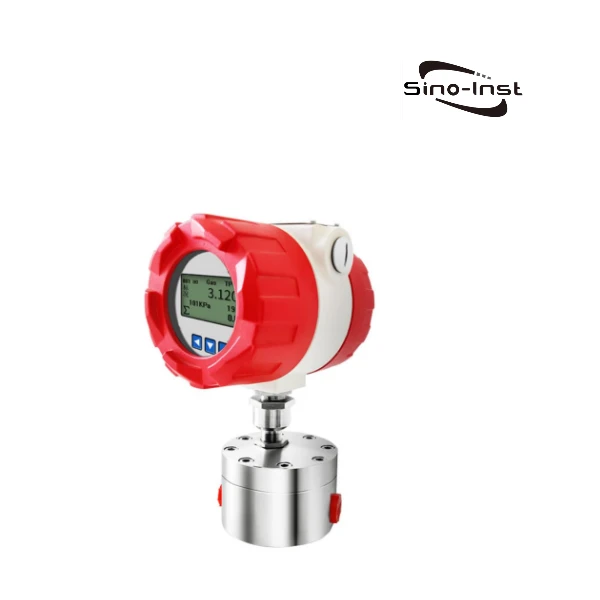
Oval Gear & Gear Flow Meters for Oils and Viscous Liquids
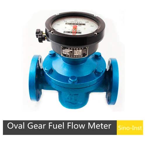
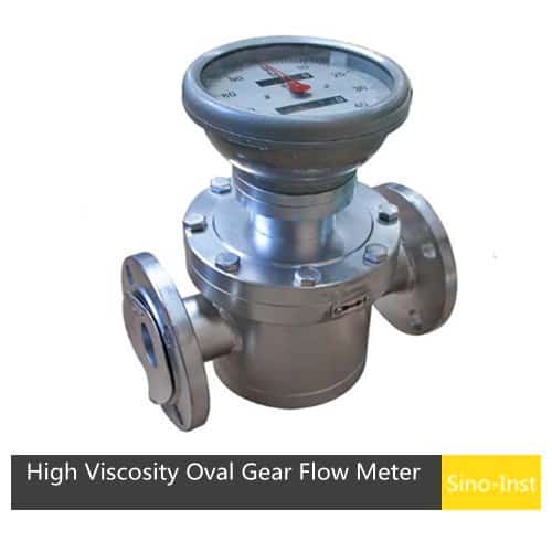
Consider Fluid Viscosity Before Purchasing
When planning to select a gear flowmeter for your measurement needs, it is essential to determine the fluid’s viscosity or its expected range of variation. Naturally, you should also confirm other key parameters, such as temperature, pressure, and the flow rate range.
If the viscosity varies significantly in your application, we can define specific operating ranges and apply corresponding correction factors to minimize errors caused by fluid slippage (leakage) and changes in flow resistance.
Low-viscosity fluids often have poor lubricity, which can accelerate gear wear. Even a slight increase in internal clearances can lead to an exponential rise in leakage; therefore, a filter should be installed upstream of the flowmeter, and units used for fiscal metering (custody transfer) should be recalibrated periodically.
For fluids that may solidify or thicken when cooled—such as bitumen, heavy fuel oil, molasses, or certain types of adhesives—the flowmeter body should be equipped with a heating jacket. In such cases, the unit must be heated before the pump is started and the fluid begins to flow. Furthermore, whenever the system is shut down, the flowmeter should be drained if at all possible.
Other factors, such as the pressure drop across the flowmeter, should also be taken into account. If you are unsure about the selection process, please provide our sales engineers with the detailed specifications of your fluid and piping system; we will then recommend the optimal configuration tailored to your specific operating conditions.
Further Reading
Zhang Wei, possesses 20 years of experience as an automation instrumentation engineer, specializing in the research, design, installation, commissioning, and maintenance of automation instruments.
Face to various instrument communication protocols (such as Modbus, Profibus, etc.), with solid hardware circuit design and software programming skills (proficient in C language and PLC programming). Has extensive project experience; projects he has led and participated in have all achieved outstanding results, improving product accuracy, reducing costs, and increasing production efficiency.
Possesses excellent communication and coordination skills and a strong team spirit, enabling him to quickly respond to customer needs and provide high-quality automation instrumentation solutions.