Home > Blog > 80GHz Radar Level for Warm Slurry Tanks with Condensation
80GHz Radar Level for Warm Slurry Tanks with Condensation
When monitoring the level of warm slurry in an open-top, circular tank approximately 3 meters high, the continuous rise of water vapor often leads to condensation on the sensor surface, which interferes with the instrument’s ability to accurately collect signals. For this specific field condition, we recommend using an 80GHz radar level sensor.
Challenges in Measuring the Level of Warm, Moist Mineral Slurry
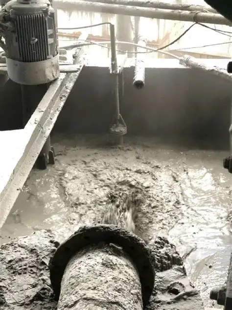
The operating environment consists of an open-top, circular storage tank approximately 3 meters in height. The tank contains a warm mineral slurry—a solid-liquid mixture. The slurry has a certain temperature. With the tank opening open, water vapor inside the tank continuously evaporates and rises, and the airflow flows directly towards the liquid level sensor installed on the top of the tank.
This type of operating condition presents three measurement challenges:
Slurry splash and buildup. The medium is a mineral slurry with a high solids content and poor flow behavior. Splashes that reach the antenna stick and build up as scale, which changes how the radar signal is reflected.
Condensation that keeps changing. Warm, moist vapor rises continuously toward the sensor and condenses into droplets or a water film on the cooler antenna face. The film absorbs and scatters the microwave signal and weakens the echo; this is the main source of interference on site. Because the tank is open-topped, workshop temperature and air movement change the evaporation rate, so the amount of condensation is never constant and fixed filter settings cannot keep up.
A short tank with little room for a blind zone. At only 3 m tall, the tank leaves little margin for the instrument’s blind zone. Once condensation or buildup forms on the antenna, near-field clutter rises quickly and can cause jumping readings, lost echoes or zero drift.
Consequently, we chose an 80GHz radar level sensor; its resistance to condensation makes it well-suited for this complex field environment.
Case: Switching from a Laser Level Meter to an 80GHz Radar Sensor
An electrical and instrumentation technician from a gold mine in Western Australia contacted us for a non-contact level transmitter for a slurry tank within their Carbon-in-Leach (CIL) processing circuit.
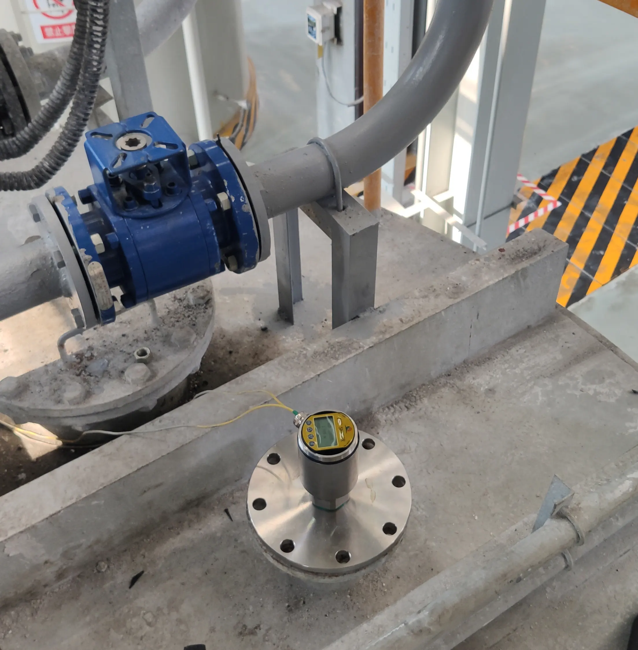
Site conditions: Cylindrical open-top tank holding heated water-solids slurry. The liquid surface sits about 3 m underneath the sensor. Hot moist fumes rise continuously and blow directly against the sensor front face.
Customer requirements: Measuring range 0.1-10 m; 24 VDC power supply; programmable 4-20 mA analog output; minimum IP56 ingress protection; ambient operating temperature 0-45 °C. The customer planned one unit for on-site trial, with seven more units to follow if the trial unit performs well.
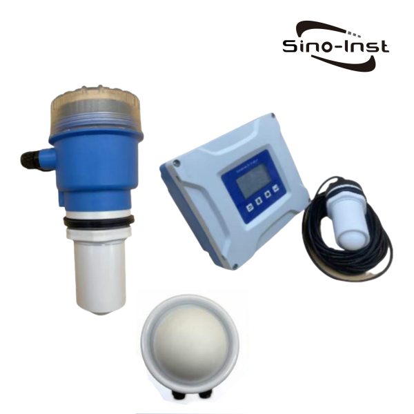
The customer initially specified a laser level transmitter. In their email, they raised a practical concern: “Will rising condensation fog the lens? How frequently will lens cleaning be needed?”
The honest answer is yes. Laser instruments work on optical principles. Water droplets on the lens or mist above the tank opening scatter light beams, weaken return signals and create erratic measurements.
We once proposed adding protective glass above the tank opening so laser beams could pass through. However, this workaround only relocates condensation from the sensor lens onto the glass panel. The glass still fogs over and needs regular manual wiping.
After reviewing the application, we determined that an 80 GHz FMCW radar would be a more suitable solution for three reasons:
Microwaves can penetrate water vapor. The hot, humid air at the tank opening has virtually no impact on an 80 GHz signal. While a thin layer of condensation on the lens may cause some signal attenuation, it will not result in a complete loss of signal, as is often the case with laser-based systems.
The lens antenna is resistant to accumulation. The PTFE lens features a smooth, hydrophobic surface and lacks the internal cavities found in horn antennas, making it difficult for condensation or splashed mineral particles to build up.
Maintenance intervals can be extended through auxiliary measures. By utilizing an integrated purge connection, instrument air or nitrogen can be introduced to create a protective air curtain in front of the lens. You can also insulate or heat the mounting bracket to keep the lens temperature above the dew point. This eliminates the need to frequently climb to the top of the tank to wipe the sensor.
This 3-meter open-top slurry tank is a typical case: the medium itself provides a strong echo (slurry contains water and has a high dielectric constant). The real challenge lies in the water vapor constantly rising from the tank opening. When selecting equipment, rather than agonizing over whether a measurement is even possible, it is better to focus on how to manage condensation and determine an appropriate maintenance frequency.
Key Design for Anti-Condensation
Structural Design
Narrow-beam antenna design: The antenna beam is focused downward, allowing the signal to avoid tank walls and internal structures (such as supports). The flat lens face also gives splashed slurry little to cling to.
Anti-adhesion coating: The antenna surface is treated with a hydrophobic coating, which prevents moisture from spreading into a continuous film. Instead, moisture tends to form small droplets that drip off, preventing long-term adhesion.
Lens material: Hydrophobic and corrosion-resistant materials, such as PTFE or FEP, are used to inhibit the formation of continuous moisture films and reduce moisture accumulation.
Auxiliary Engineering Measures
Heat tracing or thermal insulation: Insulate or heat-trace the antenna base to keep it above the dew point; operating temperature must stay within instrument rated limits.
Dry-gas purging: Feed dry nitrogen or instrument air (dew-point ≤ −40 °C) to create an air curtain at the antenna opening and block incoming moist vapor.
Optimized mounting layout: Install the unit on brackets or cross-beams, position roughly R/3 away from tank wall so as to avoid zones with heavy vapor updraft. Fit a sun/rain shield.
Signal and Algorithm Design
FMCW (Frequency-Modulated Continuous Wave) technology: Distance calculation derived from frequency offset between transmitted and returned signals.
Intelligent echo discrimination algorithm: Detect and suppress fixed-position clutter generated by antenna-surface condensation.
Near-field signal tuning: Optimized near-field processing algorithm for short low-profile tanks to minimize effective blind-zone range.
Core Advantages
Narrow beam angle: about 3° with a 75–100 mm lens antenna (a compact 40 mm lens gives roughly 7–8°). Signal energy is highly concentrated, allowing it to avoid tank walls and structural beams.
Well-suited for mounting on open-top tanks; minimizes the proportion of microwaves that strike any condensation layer on the antenna lens.
Features a wide dynamic range, a small near-field blind zone, and high resolution.
The lens design eliminates the horn cavity, preventing the accumulation of liquid.
The lens is made of hydrophobic, corrosion-resistant material (PTFE/PEEK), which is inherently hydrophobic.
Utilizes Frequency-Modulated Continuous Wave (FMCW) technology, calculating distance based on frequency differences.
Offers superior resistance to interference from water vapor, making it ideal for open-top tank environments with significant vapor fluctuations.
The anti-condensation capability of 80 GHz radar does not stem from one single special anti-condensation component. It combines high-frequency millimeter-wave physical characteristics, custom-tuned algorithms and mechanical structural optimization. While it cannot physically stop droplet formation, it greatly lessens measurement errors triggered by surface condensation.
Basic Principle
80GHz radar level sensors utilize Frequency-Modulated Continuous Wave (FMCW) technology. FMCW radar calculates distance based on the frequency difference between the transmitted signal and the echo. Rather than simply detecting the presence or absence of a signal, it continuously acquires frequency information.
Echo Processing
Analyzing the echo curve is a key method for identifying interference caused by condensation. If the intensity of the primary echo drops significantly or the waveform appears abnormal, the antenna surface should be checked for contamination, and the tank roof should be inspected for liquid accumulation or excessive vapor.
The instrument automatically masks stationary interference signals and prioritizes tracking the valid echo that shifts with the liquid level; it will not misidentify water droplets on the antenna as the liquid surface.
High-frequency characteristics
At 80 GHz, the wavelength is approximately 3.75 mm, so a 75–100 mm lens antenna can focus the beam to about 3°. Beam angle depends on lens size: a compact 40 mm lens gives roughly 7–8°. The advantage of a narrow beam is that the signal energy can be concentrated on the surface of the slurry below, avoiding the tank walls and supports.
80GHz vs 26GHz Radar for Warm Slurry Tanks
Comparison Item
80 GHz FMCW Radar
26 GHz Radar
Beam angle
About 3° with a 75–100 mm lens antenna
About 8° with a 100 mm horn; wider with smaller antennas
Near-field blind zone
Small; suits a 3 m tank where the high level sits close to the antenna
Larger; high-level readings close to the antenna are harder to separate from clutter
Antenna face
Flat PTFE lens with no cavity for condensate or slurry to collect
Horn antennas have a cavity where condensate and splashed slurry can collect
Effect of a water film
Higher attenuation per mm of film, offset by a stronger, focused echo
Lower attenuation per mm of film, but the wider beam picks up more wall and support echoes
Fit for this tank
Recommended for open-top, warm mineral slurry tanks
Workable where condensation is mild or intermittent
Slurry Operating Condition Selection and Installation Considerations
Key Selection Criteria
1. Dielectric constant consideration: Mineral-rich slurry normally holds metal-bearing solid particles and shows high dielectric constant with strong echo return. An 80 GHz non-contact radar is the first choice.
If thick persistent foam covers the slurry surface, microwave energy is absorbed or scattered. In such cases, users should evaluate guided-wave radar or radar transmitters enhanced with advanced echo-processing algorithms.
2. Antenna and material specification: Select lens-style antennas or large-aperture horn antennas. Wetted components including antenna and flange seals should preferably use PTFE cladding or solid PTFE construction for slurry corrosion and abrasion resistance. For high-temperature process conditions, corrosion-resistant alloys like Hastelloy represent viable choices.
3. Explosion-proof & environmental rating: Mineral-slurry processes may release flammable volatile components. Select proper explosion-proof ratings (e.g. Ex d IIB T5 Gb) according to site hazardous-area classification. IP68 ingress protection rating is recommended to withstand outdoor exposure, condensation and dust accumulation.
4. Blind zone & measuring range: Blind-zone dimension varies by antenna type, overall measuring span and mounting nozzle geometry. During radar level sensor selection, ask the manufacturer to calculate upper and lower blind-zone values against tank height. Ensure real working high-/low-liquid-level points never fall inside instrument blind zones.
Installation Precautions
1. Mounting position: Arrange installation points on tank roof, keep distance away from inlet ports, outlet ports and agitators. Guarantee unobstructed beam path within minimum one-meter radius, free of ladders, heating coils and limit switches.
2. Blind-zone and beam-path check: Maximum process liquid level should never enter measurement blind zone. No internal equipment shall block radar beam. For domed or curved tank roofs that generate multi-path reflection, offset mounting away from exact geometric center delivers better performance.
3. Bracket / cross-beam mounting: Set installation location approximately R/3 away from tank wall to stay out of central strong-vapor-updraft zone. Meanwhile keep clear of feed inlet and slurry-splashing regions to minimize direct hot-humid airflow hitting antenna surfaces.
For open-top tanks exposed to plant or outdoor cross-winds, fit sun-rain protective cover to mitigate disturbance caused by direct sunlight and rainfall.
4. Wiring and grounding: Electrical wiring work must be completed by certified technicians; never service powered-on units. Maintain grounding resistance ≤ 4 Ω using dedicated ground electrode; avoid sharing ground points with high-power equipment. Robust waterproof and moisture-proof treatment is essential for outdoor installation.
5. Commissioning and maintenance: Perform empty-tank and full-tank calibration post-installation to verify correct 4 mA / 20 mA mapping. Given slurry fouling risks, schedule periodic antenna cleaning within preventive maintenance routines.
For reactors, buffer knockout tanks and similar process equipment, operating temperatures tend to run high, and steam together with condensate commonly appear within the vessel gas space. When carrying out…
In a vacuum reactor with a stirrer, the stirrer blade is mounted on the central axis of the vessel; for most of a batch run, the gas phase space remains…
For a project involving level measurement in a sodium hydroxide (NaOH) storage tank, the client had previously used pressure-based level transmitters. Given the corrosive nature of the strong alkaline medium,…
FAQ
Radar level transmitters run on FMCW technology. They calculate distance, and from it the level, by analyzing the frequency offset between transmitted signal and reflected echo signal.
Slurry-service level instruments fall into contact-type and non-contact-type categories. Common products include capacitive level sensors, RF-admittance transmitters, tuning-fork switches, guided-wave radar, non-contact radar, float-type instruments and hydrostatic pressure transmitters.
80 GHz FMCW radar level transmitters represent preferred hardware for slurry conditions. Pay attention to hydrophobic lens material and small blind-zone design. Compared against lower-frequency radar products, 80 GHz FMCW radar offers better performance facing condensation and process-side material fouling.
Hot slurry releases rising vapor that easily condenses on antenna surfaces. 80 GHz radar level sensors equipped with PTFE or FEP hydrophobic lenses are a reliable solution.
Under light-condensation circumstances, 80 GHz radar level sensors can maintain accurate measurements. Benefiting from narrow-beam design, millimeter-wave anti-water-film attenuation and FMCW modulation scheme, 80 GHz radar effectively reduces condensation-induced measurement faults for radar level transmitters.
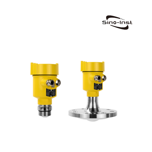
Sino-Inst supplies a complete portfolio of 80 GHz FMCW radar level transmitters including slurry-measurement variants. We also deliver custom-built level sensors for diverse slurry and high-viscosity-fluid applications: cement slurry, drilling mud, paper pulp, multiple acid-alkali-salt solutions and food-grade slurries among others.
Zhang Wei, possesses 20 years of experience as an automation instrumentation engineer, specializing in the research, design, installation, commissioning, and maintenance of automation instruments.
Face to various instrument communication protocols (such as Modbus, Profibus, etc.), with solid hardware circuit design and software programming skills (proficient in C language and PLC programming). Has extensive project experience; projects he has led and participated in have all achieved outstanding results, improving product accuracy, reducing costs, and increasing production efficiency.
Possesses excellent communication and coordination skills and a strong team spirit, enabling him to quickly respond to customer needs and provide high-quality automation instrumentation solutions.
Want to see more of our engineering guides in Google Search? Add Sino-Inst as a preferred source.