Home > Blog > Molten Salt Flow Measurement: 565°C——How to Select a Flow Meter
Molten Salt Flow Measurement: 565°C——How to Select a Flow Meter
Molten salt is not an ordinary liquid; the operating conditions are extremely demanding. Measuring the molten salt flow rate from a storage tank requires simultaneous monitoring of the liquid level, internal tank pressure, and molten salt temperature. The binary solar salt (60% NaNO₃/40% KNO₃) operates at a pressure of 2.5 bar, a flow rate of 36 kg/hr, and a temperature of 565°C. This temperature is very close to the upper decomposition limit for this type of molten salt, requiring special attention.
High temperature. Molten salts typically operate at 300–550°C or higher; standard sensors tend to fail.
Strong corrosiveness. Nitrates/fluorides are highly corrosive to wetted parts, requiring high-performance materials and seals.
Susceptibility to solidification and clogging. The solidification point is around 220°C; localized cooling can easily cause blockages.
Property drift and two-phase flow. Temperature fluctuations cause significant changes in viscosity and density.
Installation and operational stability. Large pipe diameters, vibration, inclination, and pressure fluctuations can affect the flow meter’s stability and zero-point accuracy.
Features of molten salt flow meters
Offers various installation options; for instance, the in-line insertion type entails low installation costs.
Available in a range of materials resistant to corrosion and extreme temperatures (e.g., Hastelloy, titanium).
Features a fully sealed, crevice-free (welded) design with no leakage points, capable of withstanding high pressures up to 42 MPa.
The sensor does not come into contact with the measured medium, eliminating component wear and ensuring safe, reliable operation.
Includes integrated temperature and pressure compensation, directly outputting mass flow or standard volumetric flow.
Offers optional features such as low-signal cutoff, non-linearity correction, and selectable filtering times.
Features a robust, solid-state structure with no moving parts and an insertion-style design for easy removal.
Molten Salt Flow Measurement
Molten salt consists of a mixture of potassium nitrate (KNO3), sodium nitrite (NaNO2), and sodium nitrate (NaNO3). Measuring flow within a molten salt environment is a highly challenging task. Although various molten salt flowmeters are available on the market, there are few designs and measurement methods.
Current engineering practices primarily rely on the following types of solutions:
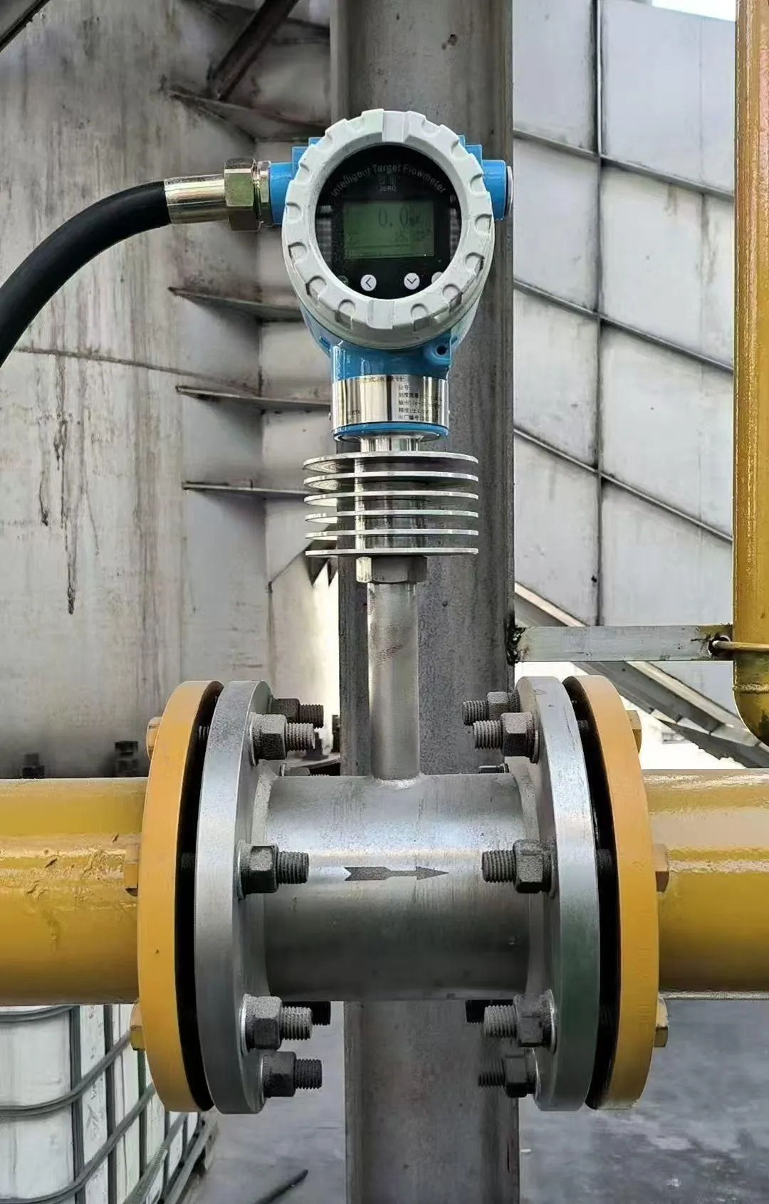
Target Flowmeter
The target flowmeter is a mature and reliable solution for molten salt metering. The capacitive target flowmeter primarily consists of a measuring tube (housing) and a novel capacitor. It offers high accuracy and strong stability, effectively avoiding issues such as significant thermal drift and poor overload resistance.
Working Principle of the Target Flowmeter
A target flowmeter works following fluid dynamic rules. When the medium passes through the measuring pipe, its kinetic energy builds up a pressure difference on both sides of the target plate. This produces a force, which makes the plate shift slightly.
The size of this force has a direct proportional relationship with the square of the medium’s flow speed.
The formula is written as: F = Cd·A·ρ·v²/2
F — Drag force acting on the component that blocks fluid flow (kg)
Cd — Drag coefficient of the flow-blocking component
A — Axial projected area of the flow-blocking part inside the measuring pipe (mm²)
ρ — Medium density under working conditions (kg/m³)
v — Average flow speed of the medium in the measuring pipe (m/s)
Target Flowmeter Technical Specifications
Medium
Liquid, gas, and steam
Size
Inline: 15–300 mm; Wafer/Clamp: 15–600 mm; Insertion: 100–2000 mm
LCD display; 4–20 mA, 0–10 V, pulse, or RS485 (optional)
Measuring tube material
Carbon steel; 304; 316L; other materials available upon request
Explosion-proof rating
ExiaIICT4, ExiaIIBT4
Protection class
IP65; IP67
Advantages of Target Flowmeters for Measuring Molten Salt Flow
High-temperature resistance; perfectly suited for molten salt operating conditions. Molten salt typically operates at temperatures between 200°C and 500°C, sometimes approaching 600°C; target flow meters are capable of withstanding such high temperatures over the long term.
Unaffected by viscosity changes. Molten salt viscosity fluctuates significantly with temperature changes; however, as target flow meters operate based on force measurement, they remain largely unaffected by viscosity variations.
No orifices or flow-restricting devices. Molten salt often contains impurities, crystallized particles, or scaling deposits; target flow meters feature an unobstructed flow path, making them resistant to clogging.
Wide range of sizes; suitable for both small and large pipelines. They can measure flow in everything from small-bore salt supply lines to large-diameter molten salt mains, offer easy installation, and have moderate requirements for straight pipe runs.
In addition to target flow meters, other Differential pressure flow meters can be used to measure molten salt flow, but they require specialized selection and design. Orifice, wedge, and Venturi flow meters are preferred choices for this application.
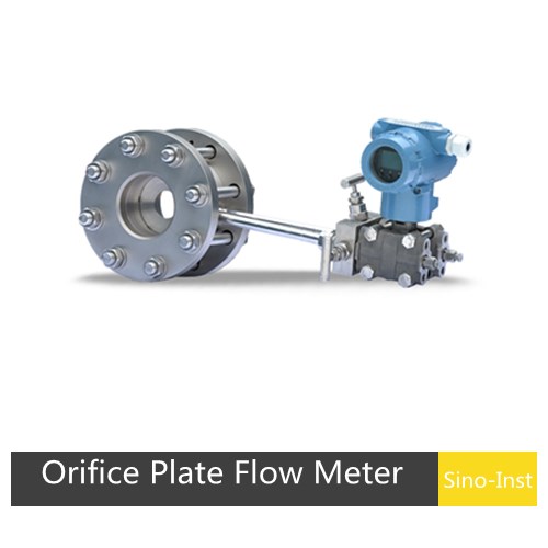
Orifice Flow Meter
Differential pressure flow meters can be used to measure molten salt flow, but they require specialized selection and design. Orifice, wedge, and Venturi flow meters are preferred choices for this application.
Working Principle of Orifice Flowmeters
The orifice flowmeter works with Bernoulli’s equation and the continuity equation in fluid mechanics. It calculates flow rate by detecting the pressure difference on two sides of the throttling component.
An orifice plate with a central hole is installed inside a vertical pipeline. Its bore diameter d is smaller than the pipe inner diameter D.
When molten salt flows through the plate, the fluid stream shrinks. From the continuity equation(Q=A₁v₁=A₂v₂), we can see that the flow velocity v₂ rises and becomes higher than v₁.
Following Bernoulli’s principle, there forms a pressure gap between the upstream pressure P₁ and downstream pressure P₂, namely ΔP = P₁ – P₂.
Idealized simplified formula:Q=K√(ΔP/ρ) (where K is the flow coefficient and ρis the fluid density).
Actual formula: Qv=C·(πd²/4)·√[2ΔP/(ρ(1-β⁴))] (where β=d/D is the diameter ratio and C is the discharge coefficient, which requires calibration based on the Reynolds number and the pressure tapping method).
Advantages of Orifice Flow Meter for measuring molten salt fluids
High resilience under extreme operating conditions. The orifice flowmeter withstands temperatures up to 800°C (covering the typical 300–600°C molten salt range) and pressures up to 42 MPa, making it compatible with molten salt system pressures.
High degree of standardization. It strictly adheres to ISO 5167/GB/T 2624 standards, eliminating the need for dedicated calibration facilities for large-diameter molten salt pipelines (e.g., DN50 to DN2000+).
Strong industrial adaptability. It is compatible with mainstream molten salt pipeline diameters; the differential pressure transmitter integrates seamlessly with DCS systems and supports instantaneous or cumulative flow measurement, as well as temperature and pressure compensation.
Wedge Flowmeter
The wedge flowmeter is a new type of throttling differential-pressure flow measurement instrument. It is capable of measuring fluids with high viscosity and low Reynolds numbers (as low as 500).
Working Principle of the Wedge Flow Meter
The core principle behind using a wedge flowmeter to measure molten salt is differential pressure measurement.
As the fluid flows past a V-shaped wedge element within the pipeline, the flow area narrows and the flow velocity increases; this results in a rise in kinetic energy and a drop in static pressure, thereby generating a differential pressure (ΔP = P₁ – P₂) between the upstream and downstream sides of the wedge that is proportional to the square of the flow rate.
Based on the Bernoulli equation and the continuity equation, the flow rate is proportional to the square root of the differential pressure: Q ∝ √ΔP.
The precise formula is qv = Cε(m, β) · (πD²/4) · √(2ΔP/ρ) (where C is the discharge coefficient, ε is the expansibility factor, m is the area ratio, D is the pipe diameter, and ρ is the fluid density).
Wedge Flowmeter Technical Specifications
Accuracy
Class 0.5, 0.2, 0.3, or 0.4 (customizable upon request)
Long-term stability
±0.2% F.S./year
Repeatability
±0.2%
Applicable media
Various liquids, gases, and steam
Minimum flow velocity
0.01 m/s
Measurement range
Typically 1:25, up to 1:33 (depending on the differential pressure transmitter’s range); can exceed 1:100 in specific cases.
Pressure loss
Approximately 1/5 of the measured differential pressure
Reynolds number range
Lower limit: 500; upper limit: ≤ 1×10⁷ (Note: at low Reynolds numbers, the applicable range narrows, and the uncertainty of the discharge coefficient increases)
Liquid viscosity
500 MPa·s or higher
Operating pressure range
-0.1 to 42 MPa
Operating temperature range
-160°C to 450°C (up to 700°C in special cases)
Applicable pipe diameter
DN10 mm to DN1200 mm (up to 2500 mm for special specifications)
Wedge ratio (h/d)
0.2, 0.3, 0.4, 0.5
DP/Pressure transmitter power supply
24 VDC
DP/Pressure transmitter output
4–20 mA DC (HART protocol optional)
Advantages of Wedge Flow Meter for measuring molten salt fluids
No moving parts. The wedge-shaped flow element lacks moving parts such as turbines or rotors, ensuring no wear during long-term operation.
Strong adaptability to low Reynolds numbers and high viscosities. It remains stable at low Reynolds numbers, is capable of measuring high-viscosity molten salts, and provides a stable differential pressure signal.
High-temperature resistance. Specifically designed for molten salt applications, the wedge flow meter can operate at temperatures up to 600°C (or up to 700°C in special cases).
Corrosion resistance. Constructed from materials such as Hastelloy and Inconel, the surface hardness can exceed HRC62, enabling resistance to the chemical corrosion caused by high-temperature molten salts.
Venturi Flow Meter
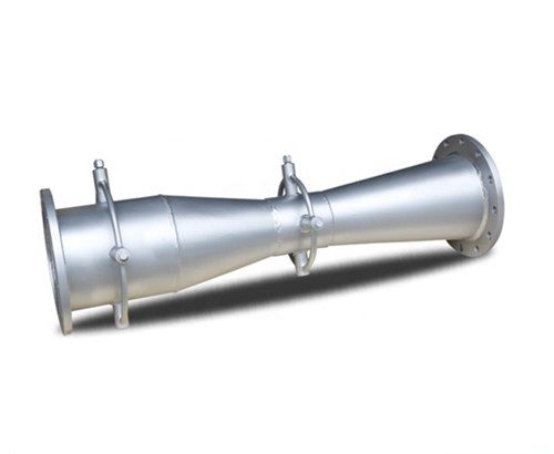
The Venturi flow meter is a type of differential pressure flow meter. It consists of a converging section, a throat, and a diverging section, and is installed in the pipeline where flow measurement is required.
As a standard throttling device, it is designed to minimize both the required length of upstream and downstream straight pipe sections and the pressure drop.
Working Principle of the Venturi Flow Meter
The operating principle of the Venturi flow meter is based on Bernoulli’s equation.
In the steady, ideal flow of an incompressible fluid, the total energy at any point within the fluid remains constant.
The total energy consists of pressure energy, kinetic energy, and potential energy (also known as datum energy).
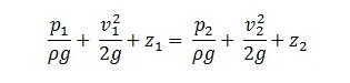
Mathematical expression:
Bernoulli’s equation for the fluid flowing through section 1 and section 2 is as follows:
Venturi Flow Meter Technical Specifications
Nominal diameter
50 mm ≤ DN ≤ 1200 mm (calibration required outside this range)Rough-cast contraction section: 100 mm ≤ DN ≤ 800 mmMachined contraction section: 50 mm ≤ DN ≤ 250 mmRough-welded sheet-metal contraction section: 200 mm ≤ DN ≤ 1200 mm
Advantages of Venturi Flowmeters for Measuring Molten Salt Flow
Resistant to high temperatures and pressures. Venturi flow meters operate stably over the long term in high-temperature molten salt and are insensitive to pressure fluctuations.
Safe and low-maintenance. Venturi flow meters have no moving parts, are resistant to leakage, and offer high reliability.
Highly compatible with molten salt systems. They provide good accuracy and repeatability with a moderate turndown ratio, covering the typical flow ranges encountered in molten salt applications.
How to Select a Flow Meter for High-Temperature Media?
Target Flowmeter
When selecting a target flowmeter, the following points should be considered:
Flow range. Selecting a range that is too large or too small may result in an inability to measure or inaccurate measurements.
Measured medium. Understand the properties of the medium, such as temperature, pressure, and viscosity. Ensure that the materials of the target flowmeter are compatible with the medium.
Installation location. Ensure that the requirements for straight pipe sections upstream and downstream of the flowmeter are met.
Consult with the manufacturer or a professional when selecting a target flowmeter to ensure the accuracy and reliability of the selection.
Differential Pressure Flowmeter
Differential pressure flow meters—such as orifice plates and Venturi tubes—operate by using a restriction element to create a local contraction in the pipeline, calculating the flow rate based on the pressure difference between the upstream and downstream sides.
So you need to consider:
Minimum-common-maximum flow
Minimum-common-maximum pressure 3.Minimum-common-maximum temperature
Pipe diameter, wall thickness 5.Pipe material
Whether it is necessary to configure a temperature sensor and a pressure sensor for temperature and pressure compensation.
Furthermore, installation requirements are stringent; typically, straight pipe runs of 10 diameters (10D) upstream and 5 diameters (5D) downstream are required. The accuracy of these meters often depends more on proper installation than on the instrument itself.
Selection can be based on the following parameters:
Medium
Pipe size (bore)
Pressure
Temperature
Flow rate
Accuracy
Output signal and communication method
Connection type
1. Structure and Pressure Loss
An orifice flowmeter features a thin, centrally bored disc installed within the pipeline and incurs significant permanent pressure loss.
A Venturi flowmeter consists of a smooth conduit comprising a converging section, a throat, and a diverging section; its pressure loss is only 10%–20%.
2. Accuracy and Stability
Orifice flowmeters have a long-term accuracy of ±1%–±2% and require periodic calibration.
Venturi flowmeters offer stable discharge coefficients and higher accuracy.
3. Installation and Cost
Orifice flowmeters have a simple structure and low cost but require long straight pipe sections (≥10D upstream and ≥5D downstream).
Venturi flowmeters have a complex structure, resulting in higher manufacturing and installation costs.
Standard air flow meters typically operate at temperatures up to 120°C. For higher-temperature air, high-temperature vortex flow meters or high-temperature thermal mass flow meters can be selected for measurement. Sino-Inst offers vortex flow meters customizable for temperatures of 250°C, 350°C, 400°C, and 500°C, while our thermal gas mass flow meters can be customized for temperatures up to 800°C.
A thermal mass flow meter is a type of flow meter based on thermal principles. It directly calculates gas mass flow by measuring the heat loss that occurs as the fluid flows past a heated element.
Thermal mass flow meters operate based on the phenomena of thermal diffusion and thermal convection. The underlying principle is that as fluid flows past a heated element, it carries away a certain amount of heat, causing the element’s temperature to drop; the amount of heat removed is directly proportional to the fluid’s mass flow rate. This measurement method directly reflects mass flow, eliminating the need for temperature or pressure compensation.
A heat meter—also known as a thermal energy meter—is a measuring instrument used to quantify and display the heat released or absorbed by water or other heat-carrying fluids flowing through a heat exchange system. It is a critical device for measuring the actual thermal energy consumed by users in heating systems and is widely used in residential, commercial, and industrial facilities served by district heating. It enables billing based on actual heat consumption, thereby promoting energy conservation and fair charging.
Steam is the most widely used heat-transfer medium across various sectors, including industrial production, heating, and cooling. There is a significant demand for steam flow measurement, which plays a crucial…
Hydrochloric acid is a vital basic chemical raw material widely used across various sectors, including the chemical industry, metallurgy, water treatment, food processing, pharmaceuticals, and electronics. Selecting the appropriate flow…
Thermal gas mass flow meters are the preferred instruments for measuring the flow of dry, stable gases—whether pure gases (such as oxygen, compressed air, nitrogen, chlorine, etc.) or gas mixtures…
Biogas is a form of clean energy, primarily composed of methane (CH4) and carbon dioxide (CO2). In the fields of renewable energy, environmental protection, and energy management, biogas flow measurement…
After a period of use, electromagnetic flow meters may experience a decrease in accuracy. Magnetic flow meter calibration eliminates systematic errors inherent in the instrument, ensuring the reliability of its…
Nitrogen Flow Controllers are devices specifically designed for measuring and controlling nitrogen flow. They not only measure the volumetric or mass flow rate of nitrogen, but crucially, they also control…
Zhang Wei, possesses 20 years of experience as an automation instrumentation engineer, specializing in the research, design, installation, commissioning, and maintenance of automation instruments.
Face to various instrument communication protocols (such as Modbus, Profibus, etc.), with solid hardware circuit design and software programming skills (proficient in C language and PLC programming). Has extensive project experience; projects he has led and participated in have all achieved outstanding results, improving product accuracy, reducing costs, and increasing production efficiency.
Possesses excellent communication and coordination skills and a strong team spirit, enabling him to quickly respond to customer needs and provide high-quality automation instrumentation solutions.