Home > Blog > Inline Pressure Transducer Guide: Types, Selection & Featured Products
Inline Pressure Transducer Guide: Types, Selection & Featured Products
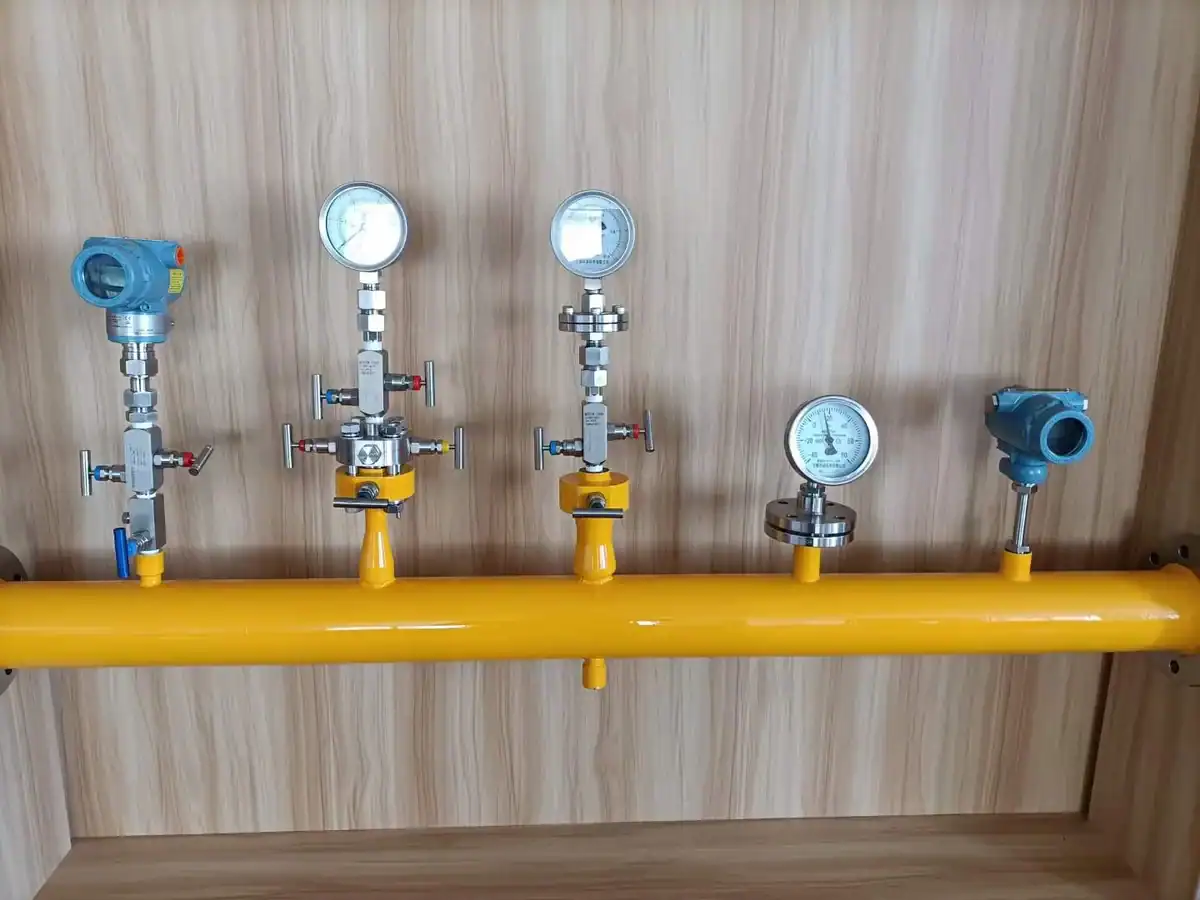
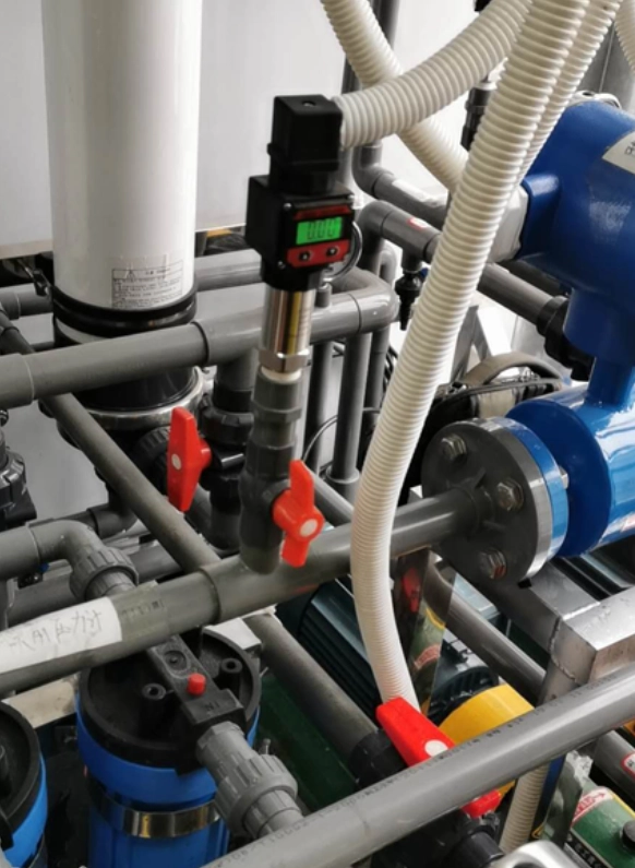
An inline pressure transducer is a compact pressure transmitter that screws directly onto the pipeline via a single threaded interface. The sensitive diaphragm is in close contact with the medium, without manifolds or remote transmission diaphragms. This form factor is most commonly found in hydraulic systems, compressed air mains, cooling water circuits, HPLC process lines, and OEM equipment.
For systems built on a fieldbus rather than an analog loop, consider a CAN bus pressure transducer that outputs CANopen or a custom CAN 2.0B protocol.
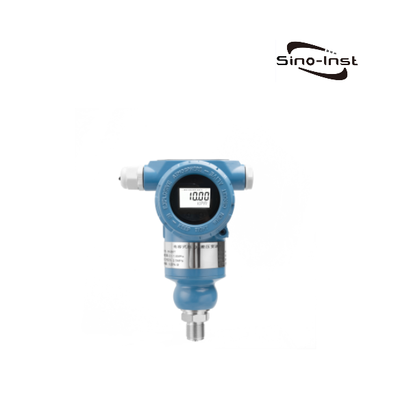
Sino-Inst manufactures and supplies 10 models of its SI series inline pressure transmitters, covering ranges from -100 kPa to 1000 MPa, and media temperatures from -252 °C to +300 °C. They support 4-20 mA, 0-5 V, 0-10 V, RS485, and HART outputs, with ATEX/IECEx explosion-proof options available.
Send us your process range, medium, process interface, and output signal, and our engineers will provide a quote the same day.
Inline pressure transducers are the most common type of transducer used in industrial pressure measurement. They are primarily distinguished from other pressure transmitters by their structure. Based on our experience, inline pressure transducers have three key structural features:
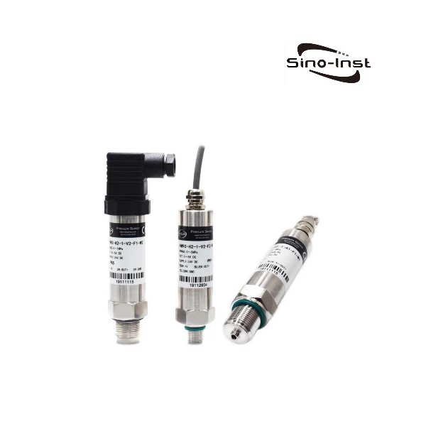
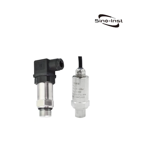
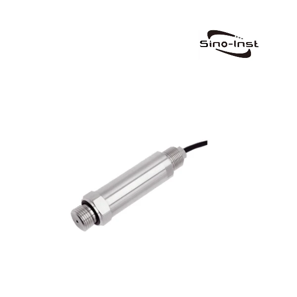
Single process interface: One thread (G, NPT, or metric M20×1.5) directly screws onto the pipeline interface, with the sensitive diaphragm facing the medium. Without manifold or capillary remote transmission diaphragm.
Single electrical connection: Top exit, Hirschmann DIN 43650 / M12 / aviation plug / potted cable direct exit.
Differences from other common installation methods:
Form
Key Features:
Is it inline?
Differential pressure (DP)
Dual-port capsule + valve manifold
No
Flange-mount
Flanged connection, commonly used for tank openings and large diameters
No
Submersible / hydrostatic
Long cable + immersion in liquid
No
Diaphragm seal with capillary
Remote diaphragm + capillary tube
No
Inline screw-mount
Single thread + compact design + welded housing
Yes
In terms of spelling, “inline,” “in-line,” and “in line” refer to the same thing and can be used interchangeably. However, the terms “sensor,” “transducer,” and “transmitter” are slightly different.
Distinguishing between Sensor, Transducer, and Transmitter
Pressure sensor, pressure transducer, and pressure transmitter correspond to three different stages in the signal chain: the sensing element, the signal conditioning circuit, and the standard loop output. These three terms are often used interchangeably in daily purchasing and our quotations. For accurate differentiation, refer to the “Output Signal” section on the product page:
Output 4-20 mA standard current loop: named as transmitter
Output 0-5 V / 0-10 V / 0.5-4.5 V proportional voltage: named as transducer
Output bare mV/V signal (requires external conditioning circuitry): named as sensor
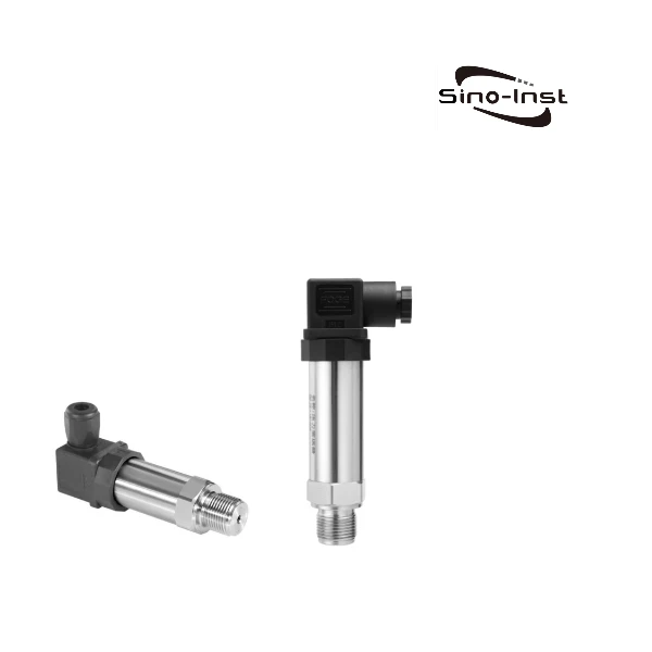
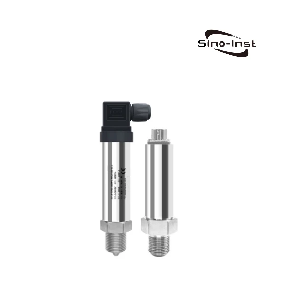
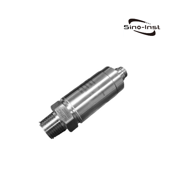
Featured Inline Pressure Transducers
Below are the inline pressure transducers that Sino-Inst regularly supplies. They are listed in two groups: Standard (for industrial use with clean media at normal temperature) and Extreme-Condition (for special operating conditions). You can select directly.
Inline pressure transducers are primarily used for real-time pressure measurement in industrial liquid, gas, and steam pipelines. Sino-Inst products are commonly used in the following 7 application areas:
Hydraulic Systems
Hydraulic power units, injection molding machines, machine tools, and hydraulic circuits in construction machinery. High pressure (10–700 MPa is common), severe pulsation, and high vibration. Selection should consider fatigue life and vibration immunity indicators. Compact pressure transducers cover standard ranges; the SI-702 high-pressure model is used for testing presses and heavy-duty hydraulic systems.
Compressed Air Mains
Plant compressed air mains, air tanks, air compressor outlets, and before and after filters. The medium is relatively clean but contains oil mist and condensate; the range is typically 0–10 bar / 0–1.6 MPa. Basic silicon piezoresistive transducers like the SI-1180 and Compact can cover most scenarios.
Cooling Water Circuits
Cooling tower return water, process cooling water, condensers, and air conditioning mains. The medium is non-corrosive but contains chloride ions, suspended particles, and algae, making it prone to scaling over time. The SI-1102 ceramic diaphragm is more durable in these conditions, while the SI-1180 is used in loops with better water quality.
OEM Machinery
Installation equipment internal piping pressure monitoring, automation equipment, robotic end effectors, and compact OEM equipment. These scenarios prioritize cost, installation space, and batch consistency. The Compact Pressure Transducer and SI-1180 are the preferred choices for OEM mass production, with customizable ranges and interface specifications.
Process Gas & Semiconductor Lines
Semiconductor high-purity gas piping (N2, O2, H2, Ar), CVD/PVD reaction chamber inlet, and specialty gas distribution. Hydrogen processes require explosion-proof (ATEX/IECEx) protection, and the high-purity medium must be free of metal contamination. Diaphragms can be customized with electropolished 316L or Hastelloy. A common configuration is the SI-1188 explosion-proof type combined with the SI-1185 intelligent RS485 multi-machine co-line solution.
Extremely Low Temperature Liquids and Gases
Gas such as CO2, N2, H2, and HE are mostly at temperatures as low as -60℃, and can even liquefy to -196℃ and -252℃. Most pressure transmitters cannot measure such extreme low-temperature media. Sino-Inst offers the SI-2088 and CPT-20SD1, specifically designed for customized low-temperature media pressure measurement solutions.
Extremely High Temperature Gases and Liquids
Media such as steam, heat transfer oil, and engine exhaust have relatively high temperatures, ranging from 100℃ and 250℃ to as high as 850℃. Conventional pressure transmitters have a media temperature resistance of 85℃. Sino-Inst supports customized high-temperature inline pressure transmitters, with customizable pressure and temperature ranges.
Inline vs Submersible vs Sanitary vs Flange-Mount
Based on our years of experience in industrial process pressure measurement, we have summarized and compared these installation methods so that you can intuitively choose the appropriate installation method.
Form
Installation Methods
Suitable Media
Typical Measurement Range
Typical Applications
Inline
Single-threaded direct screw-in installation (G / NPT / M20×1.5)
In short, you can choose inline pressure transducers in the following operating conditions:
The piping features standard threaded connections (G, NPT, M20×1.5);
The medium does not require CIP cleaning or submersible level measurement;
Installation space is limited, so manifolds or long cables are not permitted;
OEM mass production requires consistent quality across multiple batches;
If the interface on the process line is already a flange or Tri-Clamp, select Flange-Mount or Sanitary accordingly. Do not force the use of inline adapters. Adapters will increase leakage points and pressure loss.
How to Select an Inline Pressure Transducer (6-Step Checklist)
Below are the six hard parameters engineers should align on the RFQ before ordering an inline pressure transducer. Start with the overview table, then walk through the six-step decision logic.
Parameter
Common options
Engineer’s note
Range
-100 kPa to 1000 MPa, any standard step
Choose process max × 1.5 and round up to the next step
Process connection
G1/4, G1/2, NPT 1/4, NPT 1/2, M20×1.5, M22×1.5
Specify thread spec plus seal type (O-ring, flat face, conical)
Output signal
4-20 mA, 0-5 V, 0-10 V, RS485, HART
4-20 mA for long field runs; 0-10 V for OEM board-level; RS485 for multi-drop digital
Accuracy class
0.1% / 0.2% / 0.25% / 0.5% FS
0.5% is enough for general industrial use; pick 0.1% for custody transfer or calibration standards
Ingress / Hazardous area
IP65 / IP67 / IP68; ATEX, IECEx, Ex ia, Ex d
IP65 minimum outdoor; IP68 for submersion; confirm hazardous zone before sizing
Media compatibility
304, 316L, Hastelloy C, ceramic, tantalum, PTFE
Hastelloy for chloride-bearing media; ceramic or tantalum for strong corrosion
Step 1. Range: Process Maximum Pressure x 1.5
Round up to the next standard step. For example, a process maximum of 35 MPa fits a 40 MPa or 50 MPa transducer with 25-50% headroom. Long-term operation at full scale shortens diaphragm life.
Step 2. Media: Diaphragm Material
Clean water, air, clean hydraulic oil → 304 or 316L
Chloride-bearing water, seawater → Hastelloy C
Acids, alkalis, organic solvents → ceramic (SI-1102) or tantalum
High-purity gases → electropolished 316L or Hastelloy (custom)
Step 3. Process Connection: Match the Line
Check what thread the process line uses: G, NPT, or M20x1.5. If the line already has flanged or Tri-Clamp interfaces, do not adapt them to inline; pick the matching Flange-Mount or Sanitary type instead.
Step 4. Media Temperature: Pick the Accessory
≤ +85 °C: standard inline, direct mount
+85 to +300 °C: add a cooling siphon or heat sink
-50 to -252 °C: choose CPT cryogenic series
> +300 °C: choose SI-2088 series (water-cooled high-temperature variant)
Step 5. Output Signal: Match the Controller
Check what input the PLC, DCS, or board accepts. 4-20 mA is the field default for runs of 50 m or more, or for hazardous areas. Use 0-10 V for OEM board-level, RS485 Modbus for multi-drop, and HART for remote configuration and diagnostics.
Step 6. Ingress and Hazardous Area: Protection Rating
Indoor use is fine with IP65. Outdoor with rain exposure needs IP67; basins or long-term submersion need IP68. Hazardous areas follow Zone 1/2 classification, mapped to Ex ia or Ex d ratings. Get the area classification drawing from the process engineer before ordering.
Other Parameters to Confirm
Electrical connector: Hirschmann DIN 43650 / M12 / aviation plug / direct cable gland
Supply voltage: standard 24 VDC; 12 V or ±15 V for specific cases
Inline measures single-point pressure (gauge, absolute, or negative). A DP transmitter measures the differential between two points. For a single pressure, vessel head, or static reading, pick inline. For flow across an orifice, filter blockage, or sealed-vessel level requiring differential, pick DP.
Standard inline transducers cover up to 100 MPa. Above 100 MPa, choose the SI-702 ultra-high-pressure series (top end 700-1000 MPa). Below 100 MPa, a dedicated high-pressure structure is not needed and a standard inline will perform.
Not directly. Steam typically runs 150-350 °C, and silicon sensing elements become unreliable above +85 °C. Two approaches work: install a pigtail siphon so steam condenses to water before the transmitter, or pick the SI-2088 series with a heat sink, which tolerates up to +300 °C process temperature.
Match the existing process line. Chinese and European hydraulic systems usually run M20x1.5 or G1/2; North American and oil-and-gas applications run NPT. Sino-Inst customizes all three on every SI-series model. Confirm the line thread spec and seal type (O-ring, flat face, conical) before ordering.
Submersible Pressure Transducers are a special type of pressure transmitter. Equipped with a sturdy, durable and airtight stainless steel casing with a protection level of up to IP68. The probe measures static pressure. This allows conclusions to be drawn about the current liquid level, i.e. the height of the liquid column above. Commonly used for … Read more
The Sanitary Pressure Transducer features a unique hygienic process connection, specifically designed for measurements in food processing, pharmaceutical, and clean-in-place systems where hygiene is critical. Sino-Inst’s Sanitary Pressure Transducer utilizes proven thin-film sensor technology and a hygienic isolation seal. Both the wetted parts and the diaphragm are made of 316L stainless steel and laser-welded for … Read more
Steam Pressure Sensors also called Steam Pressure Transducers, play a pivotal role in modern industrial applications. In the world of steam boilers, the precise measurement of boiler pressure is paramount, and the differential pressure can make the difference between optimal output and system failure. As industries lean more towards digital solutions, these sensors provide clear … Read more
Differential pressure transmitters are transmitters that measure the difference in pressure across the transmitter. Output standard signals (such as 4~20mA, 0~5V). Differential pressure transmitters are mainly used to measure differential pressure, pressure and negative pressure of liquids, gases and steam. It is also possible to measure liquid levels in open or pressurized vessels. Equipped with … Read more
Selection of pressure transmitters is related to its use. Generally, when selecting, it is necessary to consider many factors comprehensively. Including what kind of pressure to measure, what kind of pressure medium, accuracy requirements, temperature range, and how to obtain The output signal? Do you need an interchangeable pressure transmitter? Stability and so on. When … Read more
Zhang Wei, possesses 20 years of experience as an automation instrumentation engineer, specializing in the research, design, installation, commissioning, and maintenance of automation instruments.
Face to various instrument communication protocols (such as Modbus, Profibus, etc.), with solid hardware circuit design and software programming skills (proficient in C language and PLC programming). Has extensive project experience; projects he has led and participated in have all achieved outstanding results, improving product accuracy, reducing costs, and increasing production efficiency.
Possesses excellent communication and coordination skills and a strong team spirit, enabling him to quickly respond to customer needs and provide high-quality automation instrumentation solutions.