Home > Densitometers > Inline Refractometer for Process Concentration & Brix Measurement
Inline Refractometer for Process Concentration & Brix Measurement
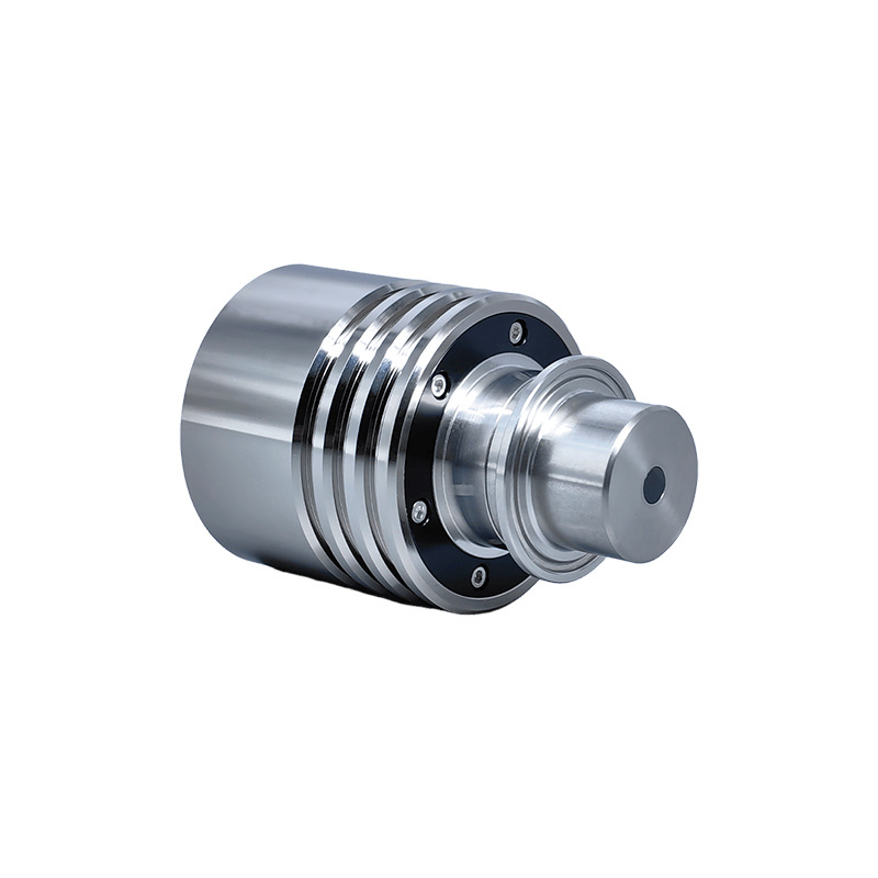
An inline refractometer is a real-time concentration measurement instrument based on the principle of optical refraction. When light passes from one medium into another, its path is deflected; this angle of deflection is directly related to the content of soluble solids in the liquid.
The Inline Refractometer measures and displays parameters required by users, such as concentration (%) and Brix. It can be directly installed on pipelines or reactors to enable real-time, continuous, and online monitoring of liquid concentration during the production process. Compared to traditional manual sampling methods, the inline refractometer completely eliminates sampling delays and human error.
Real-time, rapid detection ensures production quality and facilitates maintenance.
High precision, unique algorithms, and automatic temperature compensation.
Customizable installation methods and cleaning options.
Configurable interfaces include 4–20 mA, RS-485, RS-232, and USB; optional modules for alarm, cleaning, and switch signal outputs are also available.
Critical angle of total internal reflection. Readings are not affected by bubbles, suspended solids or sample color.
Robust Construction
Sapphire prism with 316L stainless steel housing. Resists corrosion and is rated to 1.5 MPa.
Temperature Compensation
A built-in sensor tracks process temperature in real time and automatically compensates readings to a reference temperature.
Low Maintenance
Modular design with no wearing parts, so it needs very little routine service.
Flexible Installation: Adapts to complex environments such as pipelines and tanks, saving installation time and costs.
Stable Measurement: Advanced technology ensures measurements are not affected by medium characteristics (bubbles, color, turbidity, etc.) or operating conditions (pressure, flow rate, etc.), providing stable and accurate data.
Convenient Calibration: Probes are rigorously calibrated before shipment and feature built-in temperature compensation, making the complete system ready for immediate use upon delivery.
Smart Customization: Equipped with a built-in concentration data processing system, users can build data models on-site and customize parameters to improve testing accuracy.
Self-Diagnostic Maintenance: Features probe status self-diagnosis to quickly pinpoint faults and minimize downtime.
On-Site Calibration: Supports refractive index (RI) calibration and adjustment, allowing for real-time correction of detection errors.
Intelligent and Durable: Utilizes an intelligent chip, requires no reagents or consumables, has low power consumption, and features a probe light source with a lifespan of up to 100,000 hours.
One-Stop Solution: Leveraging these performance advantages, it provides a one-stop solution for industrial testing, enhancing production efficiency and ensuring product quality control.
Technical Specifications
Model
CRN50
CRN52
CRN56
Measured Parameters
Refractive index, temperature, concentration, Brix (or other scales)
Displayed Parameters
Refractive index (nD), Brix (temperature-compensated per sucrose), concentration (Conc), temperature (°C)
Data Processing
Probe status diagnostics, RI calibration and adjustment, user self-modeling, multi-point temperature compensation, concentration curve correction
Concentration Range
0.0–90% Brix
0.0–100% Brix
Refractive Index Range
1.33299–1.51782
1.33299–1.57041
Process Temperature
0–60 °C
0–70 °C
-10–100 °C
Cleaning Temperature
-30–120 °C, supports CIP (clean-in-place) and SIP (sterilize-in-place)
Resolution
0.01%; refractive index 0.00001; temperature 0.1 °C
Accuracy
±0.1%; refractive index 0.0001; temperature 0.5 °C
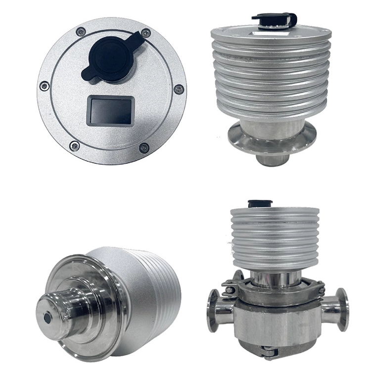
Small-bore pipe adapter, tee / cross (with sight window), sanitary adapter, etc., customized to installation conditions
Optional Accessories
Ultrasonic Cleaning Accessories
High-Pressure Gas and Liquid Flushing Accessories
Standalone Display Controller
Multi-Channel Data Acquisition and Control System
Wireless Data Transmission Module
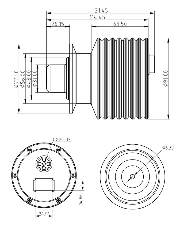
Compact clamp-style mount; available in sizes: DN25/DN50/DN65/DN80.
Total length: 121.45 mm; distance from clamp face to rear: 114.45 mm; Probe extension length: 26.15 mm; finned housing length: 63.50 mm; Clamp outer diameter: Φ77.50 mm; probe diameter: Φ31.00 mm (with options for Φ56.00 / Φ48.00 mm); Electrical connection: GX20 12-pin aviation connector; display window height: 14.86 mm.
Inline Refractometer Working Principle
1. Light Propagation and the Phenomenon of the Critical Angle
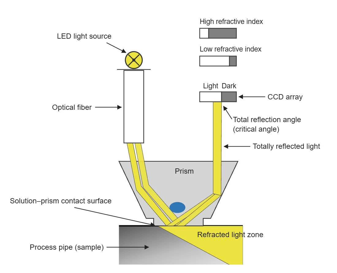
Measurements with an inline refractometer begin with the propagation of light. Light emitted by a high-brightness LED is guided through a low-loss optical fiber and introduced from a specific side of the prism. Inside the prism, the light follows a carefully designed reflection path until it reaches the interface between the prism and the liquid being measured. At this critical interface, the propagation behavior of light differs significantly due to the varying refractive indices of the two liquids.
According to optical principles, when light travels from a denser medium to a less dense medium, total internal reflection occurs at a specific angle of incidence.
In an online refractometer, some light rays satisfy the conditions for total internal reflection and are completely reflected to the other side of the prism. Furthermore, the position of the total internal reflection light changes as the critical angle varies, since the critical angle is closely related to the liquid’s refractive index; even slight changes in the liquid’s refractive index directly cause corresponding changes in the critical angle.
2. Optical-to-Electrical Conversion for Concentration Measurement
To accurately capture changes in the position of the total reflection light, the online refractometer employs a linear array CCD. It precisely detects the position of the light-dark boundary of the total reflection light, with each specific position uniquely corresponding to a specific refractive index value.
It is worth noting that there is a clear correlation between the solution concentration and the position of the light-dark boundary: as the solution concentration increases, the light-dark boundary shifts further to the left.
The online refractometer uses optical methods to measure the critical angle of the solution and employs a hybrid analog-digital principle to determine the solution’s concentration. A light source inside the sensor emits light at different angles toward the prism and the interface with the solution being measured.
Due to the different angles of incidence, the light behaves differently at the interface: some light is totally reflected, some is partially reflected, and most is refracted into the solution being measured, thereby creating a unique optical image consisting of bright and dark regions at the interface.
The angle of incidence corresponding to the boundary line between the dark and bright zones is defined as the “critical angle.” Changes in the critical angle directly alter the brightness-to-darkness ratio detected by the CCD sensor; this ratio is, in fact, a function of the refractive index.
Given the stable correlation between solution concentration and refractive index, the solution’s concentration can be accurately determined by precisely measuring the critical angle.
3. Signal Processing and Temperature Compensation
During signal detection and processing, the online refractometer uses a digital CCD (charge-coupled device) to meticulously detect the optical image and the boundary shadow line. It converts complex image information point by point into electrical signals that are easy to process. Through precise analysis of these electrical signals, the exact position of the boundary shadow line is determined, thereby accurately measuring the refractive index nD.
At the same time, the probe incorporates a high-precision temperature sensor that measures the temperature of the medium at the interface in real time.
After acquiring data on the refractive index nD and temperature T, the transmitter automatically performs temperature compensation based on a preset algorithm, thereby precisely calculating and intuitively displaying the concentration value of the liquid.
The preliminarily processed electrical signals undergo further gain amplification and are then converted into various practical parameters, such as mass concentration, solids content, Brix, density, and refractive index. These parameters are not only clearly displayed locally on the instrument but can also be transmitted over long distances via remote transmission technology, providing robust support for real-time monitoring and automated control in industrial production processes.
Featured Application
Thanks to its high accuracy, real-time performance, and stability, the Inline Refractometer has found widespread application in numerous fields.
In the food and beverage industry, it can be used to monitor concentration during the production of products such as sucrose, fruit puree, jelly, soft drinks, fructose, milk, beer, glucose, fruit juice, and bone broth, ensuring stable and consistent product quality.
In the chemical industry, it is suitable for concentration testing of various chemical raw materials and products, such as sulfuric acid, hydrochloric acid, phosphoric acid, sodium hydroxide, ammonia water, urea, surfactants, ethylene glycol, hydrogen peroxide, sodium hypochlorite, methanol, and ethanol, thereby ensuring the safe and efficient operation of chemical production.
In other industries, such as the concentration measurement of cutting fluids, coolants, DMF, DMAC, PVOH, traditional Chinese medicine concentrates, emulsions, slurries, polyurethanes, alcohol extracts, sodium carbonate, glycerin, gelatin, and collagen peptides, it also plays a vital role in helping various industries improve production efficiency and product quality.
With their advanced measurement principles and wide range of applications, online refractometers have become indispensable tools in modern industrial production and scientific research.
Installation Guide
The inline refractometer reads only the liquid touching the prism window. A good installation keeps that window fully covered by a moving, bubble-free sample.
Mounting Options
Bypass line: the sensor sits on a bypass with isolation valves, so it can be removed for cleaning or checks without stopping the process.
Main pipe: lowest installation cost, but servicing the sensor usually means a shutdown.
Pumped sampling loop: a pump circulates liquid from the tank past the sensor. Flow at the prism stays constant, which gives the best accuracy at a higher cost.
Tank wall: the liquid in the tank must keep moving, and the agitator must not reach the prism window.
Mounting Position
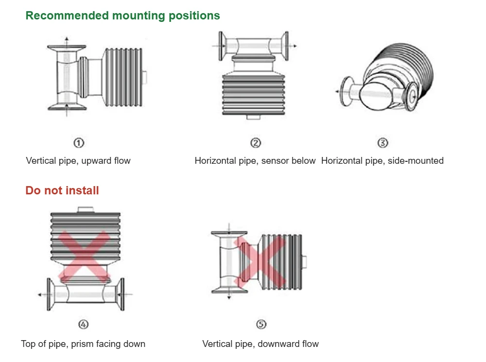
The sample must fill the pipe and cover the prism surface. Positions ① to ③ are recommended. Positions ④ and ⑤ are not allowed.
Never install the probe with the prism facing down, whether on a pipe or a tank. On a horizontal line, gas collects at the top of the pipe. In a vertical line with downward flow, the pipe may not run full.
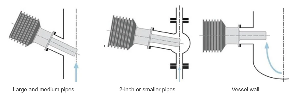
On large and medium pipes, insert the probe at an angle with the tip facing the flow. On 2-inch and smaller lines, use a flanged spool piece so the tip sits in the flow path. On vessels, mount through the wall at a point where the liquid is moving.
Before You Install
Choose the mounting option and cable route first, then match the process connection (compact clamp, or DN25 / DN50 / DN65 / DN80 flange) to the pipe or vessel nozzle.
Check that the PLC or DCS input matches the output you plan to use: 4–20 mA, RS485, RS232 or USB.
Provide a 24 VDC supply with correct polarity, voltage within ±10%, and a reliable earth connection.
Installation Notes
Use shielded cable or earth the housing to keep the analog output stable. For cable runs over 5 m, use RS485.
Sample temperature must not exceed 100 °C, and pressure on the prism window must not exceed 1.5 MPa. The probe’s ambient temperature range is -10 to 100 °C.
Keep the sensor away from strong vibration, direct sunlight, rain and heavy dust.
Filter out sand and abrasive particles, which wear the prism window. If the window fouls easily, add the CRN5-C1 ultrasonic or CRN5-C2 high-pressure flushing assembly.
Do not touch the prism with sharp objects, and do not connect the cable while power is on.
For a long shutdown, switch off the 24 VDC supply and keep the window clean so no crystals form on it.
A probe set up for one specific scale should not be used to measure the concentration of a different liquid.
What Is a Density Meter? We are discussing industrial density meters here, not laboratory densitometers. Industrial density meters are devices specifically designed to measure fluid density, performing real-time online density detection and displaying data such as density and temperature. They also support outputs of 4-20 mA, 0-1000Hz, RS485 Modbus RTU, HART, and other signals, facilitating … Read more
How to Measure Viscosity? Simply put, it involves controlling the temperature, allowing the liquid to flow or undergo shearing, recording the time, torque, or vibration damping, and then converting these values into viscosity units such as mPa·s or cSt. There are many methods for measuring viscosity. For example, the capillary method can be used for … Read more
Viscosity and its measurement are closely related to experimental scientific research and industrial production. A viscometer is a device capable of effectively measuring the viscosity of a fluid and providing a readout or an output signal. While viscosity measurements were traditionally conducted primarily in laboratory settings, technological advancements now enable such measurements to be performed … Read more
Beer brewing is an artistry that needs exactitude at each and every step of operation. By providing accurate readings, brewery flow meters help individual and professional brewers accomplish the desired balance of flavor and alcohol content in their beer, making them a staple in efficient brewing operations. Every component of a beer brewing system that … Read more
Zhang Wei, possesses 20 years of experience as an automation instrumentation engineer, specializing in the research, design, installation, commissioning, and maintenance of automation instruments.
Face to various instrument communication protocols (such as Modbus, Profibus, etc.), with solid hardware circuit design and software programming skills (proficient in C language and PLC programming). Has extensive project experience; projects he has led and participated in have all achieved outstanding results, improving product accuracy, reducing costs, and increasing production efficiency.
Possesses excellent communication and coordination skills and a strong team spirit, enabling him to quickly respond to customer needs and provide high-quality automation instrumentation solutions.