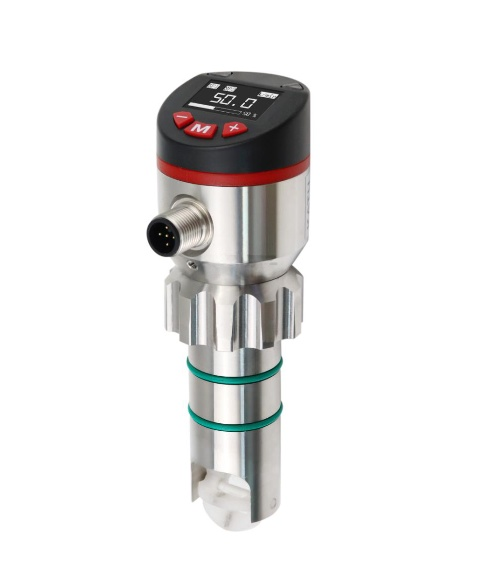
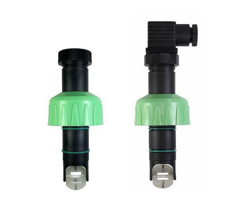
The KF10 series insert-type Paddlewheel Flow Sensor is another intelligent flow switch and a compact flow sensor. It features small size and easy setup. Built-in intelligent circuitry allows for arbitrary setting of upper and lower flow alarm values. Real-time flow status can be remotely monitored, and all parameters can be set on-site. Its impeller measures the flow rate of the medium passing through, and the data is processed by the sensor’s intelligent circuitry and can be programmed arbitrarily.
IP67 protection rating, suitable for harsh field environments;
Easy insert-type installation;
High stability and strong anti-interference capability;
High-temperature zirconia ZrO₂ (ceramic), titanium alloy, Hastelloy C
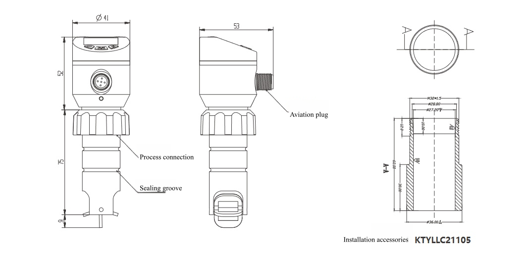
Dimensions
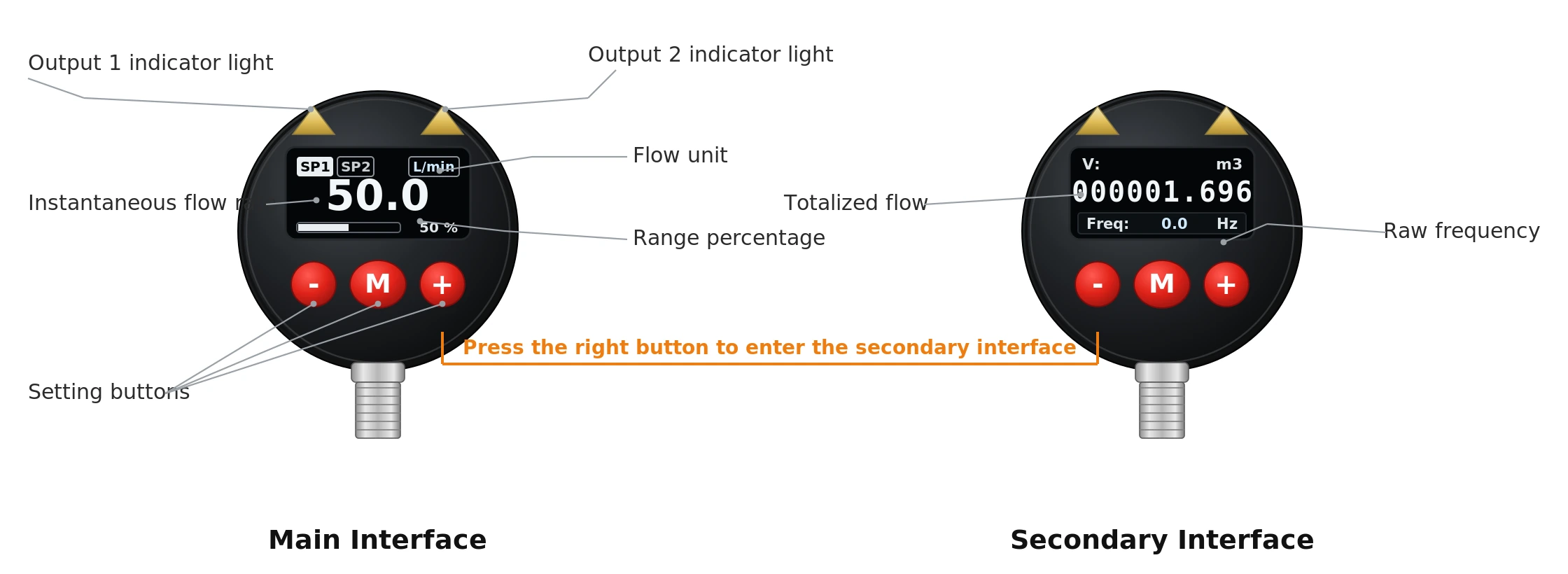
KF10 Paddlewheel Flow Sensor Local Display
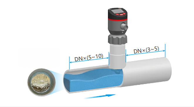
Paddlewheel Flow Sensor Installation
Straight Pipe Installation
Generally, the upstream straight pipe section length should be 5 to 10 times the sensor diameter, and the downstream straight pipe section length should be 3 to 5 times the sensor diameter. This ensures stable fluid flow as it passes through the sensor, improving measurement accuracy.
Installation Precautions
Keep away from strong magnetic and electric field interference sources, such as large motors and transformers, to prevent electromagnetic interference from affecting the sensor’s measurement accuracy and stability.
Avoid installing at the highest or lowest point of the pipe to prevent the accumulation of air bubbles or sediment that could affect the measurement.
If this cannot be avoided, consider installing an air vent or drain valve.
Installation Method
The sensor should be installed in the same direction as the fluid flow. An arrow on the sensor indicates the flow direction.
During installation, ensure the sensor is securely connected to the pipe without looseness.
For measurements of high-temperature, high-pressure, or corrosive fluids, select appropriate sensor materials and installation methods to ensure sensor reliability and safety.
Electrical Connection
Strictly follow the sensor’s electrical wiring diagram to ensure correct wiring.
Ensure proper grounding to prevent electrical interference and static electricity buildup.
For explosion-proof environments, use sensors that meet explosion-proof requirements and install them according to explosion-proof electrical installation specifications.
Debugging and Calibration
After installation, debugging and calibration should be performed to ensure the sensor’s measurement accuracy and performance meet requirements. Calibration can be performed by comparing with a flow meter of known accuracy or using a standard flow device. Adjust sensor parameters appropriately, such as range and zero point, according to actual conditions.
Order Guide
KF10-
A3
–
–
–
Description
KF10-
KF10 series impeller (paddle-wheel) flow sensor
A3
Two-channel switch / pulse / frequency + analog output
SA
Analog (flow / temperature) / switch / pulse / frequency / IO-Link
In industries such as fine chemicals, pharmaceuticals, and food processing, there is often a need to accurately measure and control small flow rates of glycerol liquids. As a viscous fluid, accurate flow measurement of glycerol is crucial for ensuring product quality and process control. Therefore, selecting the appropriate flow meter is key to ensuring measurement … Read more
How to measure the flow of viscous liquids? For example: glue, heavy oil, asphalt, etc. Commonly used flow meters may not be suitable. High Viscosity Flow Meters are instruments for measuring the flow of viscous fluids. Common high viscosity flow meters are: Oval Gear flow meters. Mass flow meters, Target flow meters, and Wedge flow … Read more
An oval gear flowmeter, also known as a displacement flowmeter, is a type of positive displacement flowmeter and offers the highest accuracy among flow instruments. It is particularly suitable for measuring the flow of highly viscous liquids such as heavy oil, asphalt, paint, diesel, and bunker fuel. An oval gear flowmeter uses a mechanical measuring … Read more
Slurry and sludge flow measurement is complex and challenging. Accurately measuring slurry flow can improve efficiency and reduce costs in industries such as wastewater treatment, water conservancy projects, river dredging, and oil well cementing. Slurry flow meters measure the volumetric flow of sludge and slurries in pipelines. Examples include cement slurry, mud, pulp, various acid, … Read more
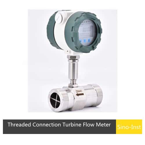
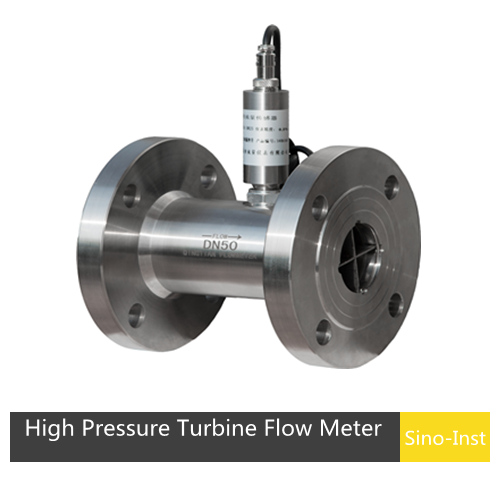
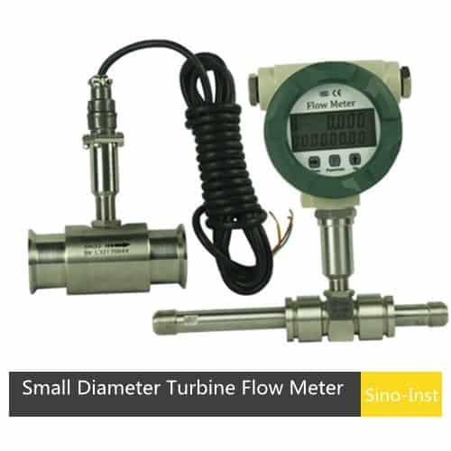
Turbine type flow meter is an important velocity flow meter. It has the advantages of easy maintenance, large flow capacity and relatively low price. It has been widely used to measure the flow of liquids and gases. Including petroleum, organic liquids, natural gas, etc. Sino-Inst is one of the manufacturers of Turbine type flow meter, … Read more
Ultrasonic vs Magnetic Flow Meter, are you confused about which one to choose? Sino-Inst, based on our years of experience in flow measurement services, has compiled this blog, hoping to help you! Ultrasonic flow meters and electromagnetic flow meters are both commonly used liquid flow meters. Because of their different working principles, they both have … Read more
Cement additives are chemical additives added during the production and use of cement. They improve the overall performance of cement products by adjusting the setting time, improving rheological properties, and enhancing durability. The main types include water reducers, retarders, early strength agents, and expansion agents. Liquid Cement Additive is a state of mixed solvent. The … Read more
Sino-Inst supplies a full range of Paddle Wheel Flow Meters, including local display and split display models. Custom materials are also available, such as PP, PVDF, stainless steel, and brass. The KF10 Paddle Wheel Flow Sensor is the preferred choice for low-cost flow measurement and control. Please feel free to contact our sales engineers for customized solutions.
Zhang Wei, possesses 20 years of experience as an automation instrumentation engineer, specializing in the research, design, installation, commissioning, and maintenance of automation instruments.
Face to various instrument communication protocols (such as Modbus, Profibus, etc.), with solid hardware circuit design and software programming skills (proficient in C language and PLC programming). Has extensive project experience; projects he has led and participated in have all achieved outstanding results, improving product accuracy, reducing costs, and increasing production efficiency.
Possesses excellent communication and coordination skills and a strong team spirit, enabling him to quickly respond to customer needs and provide high-quality automation instrumentation solutions.