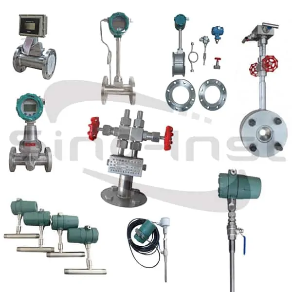
An inline compressed air flow meter installs directly into pipes from 1/8″ to 2″ and measures SCFM, Nm³/h, or m³/h — typically to ±1% accuracy for leak detection, energy audits, and cost allocation. For larger pipe diameters, an insertion-type gas flow meter can be selected. Sino-Inst primarily supplies thermal, vortex, metal rotor, and differential pressure compressed air flow meters.
Sino-Inst offers compresses air flow meters with and without local display. And 4-20mA and 0-10v outputs and for hazardous area applications are available.
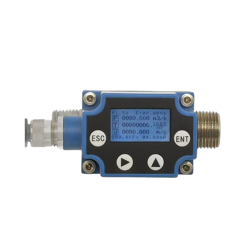
An inline compressed air flow meter is a type of inline flow meter that can be installed in conjunction with a compressed air pipeline. The dimensions of an inline compressed air flow meter must match the pipeline dimensions. During installation, the compressed air pipe is typically cut off before the Inline Compressed Air Flow Meter is installed.
How Does an Inline Flow Meter Work?
Technically speaking, Inline Compressed Air Flow Meters mainly fall into four categories: thermal, vortex, metal rotor, and differential pressure. Here’s how they work:
1. Thermal gas mass flow meter
The working principle of a thermal mass flow meter is based on the principle of heat diffusion, that is, the heat exchange relationship between a fluid and a heat source.
Specifically, a thermal mass flow meter contains two main sensors: a velocity sensor (usually a heater) and a temperature sensor. These two sensors are placed in the gas being measured. The velocity sensor is heated, while the temperature sensor measures the temperature of the gas. As the gas flow rate increases, the heat carried away also increases, causing the temperature sensor’s temperature to drop.
By measuring the linear relationship between the temperature change before and after the temperature sensor reading and the gas mass flow rate through the pipe, the gas mass flow rate can be calculated.
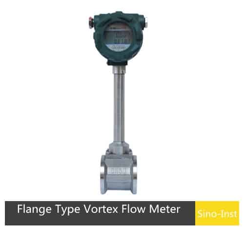
2. Vortex flowmeter
The working principle of the vortex flowmeter is based on the Karman vortex principle, which was discovered and deeply studied by the American-Hungarian scientist von Karman in 1911.
When a fluid (such as gas or liquid) flows through a non-streamlined object, pairs of vortices with opposite rotation directions will appear alternately on both sides of the object’s wake. These vortices are arranged at a certain frequency to form the so-called Karman vortex street.
The frequency of the vortex generation is proportional to the flow rate of the fluid and inversely proportional to the diameter of the vortex generator. The relationship is Sr=fd/V.
Where Sr is the Strouhal constant, f is the vortex frequency, d is the vortex shedding diameter, and V is the flow velocity. The vortex flowmeter measures the vortex shedding frequency to deduce the fluid velocity or flow rate.
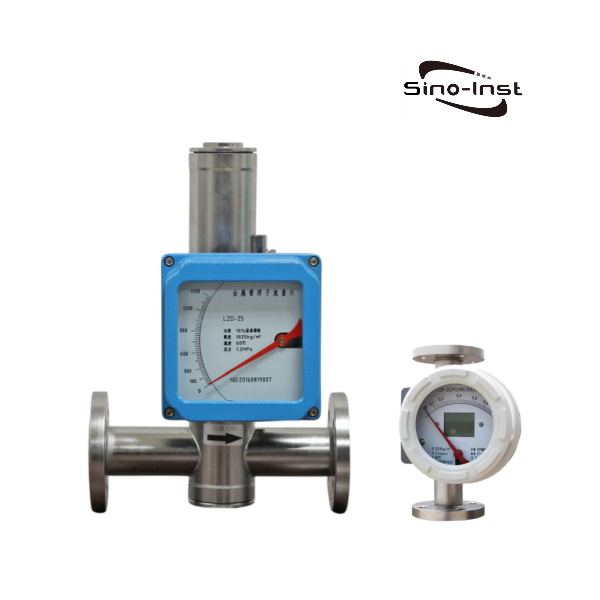
3. Metal rotor flowmeter
The structure of a rotameter flow meter is a vertical tapered metal tube whose cross-sectional area gradually expands from bottom to top. There is a rotor (or float) made of metal or other materials that can rotate freely. The fluid to be measured enters from the bottom of the metal tube and flows out from the top.
When the fluid flows through the vertical tapered tube from bottom to top, the rotor is acted upon by two forces: one is the vertical upward pushing force, which is equal to the pressure difference generated by the fluid flowing through the annular cross-section between the tapered tube and the rotor.
The other is the vertical downward net gravity, which is equal to the gravity on the rotor minus the buoyancy force of the fluid on the rotor. When the flow increases so that the pressure difference is greater than the net gravity of the rotor, the rotor rises. When the pressure difference is equal to the net gravity of the rotor, the rotor is in equilibrium. That is to stay in a certain position.
A reading is engraved on the outer surface of the metal tube. According to the dwell position of the rotor, the flow rate of the measured fluid is read.
The rotameter is a variable cross-section constant pressure differential flowmeter. The pressure difference acting on the upstream and downstream of the float is a constant value. The annular cross-sectional area between the float and the tapered tube changes with the flow rate. The position of the float in the tapered tube reflects the flow rate.
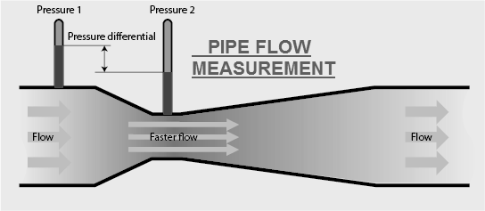
4. Differential pressure flow meter
A differential pressure flow meter measures flow by measuring differential pressure. It is based on the principle that there is a certain relationship between the pressure difference and the flow rate generated when the fluid flows through the throttling device.
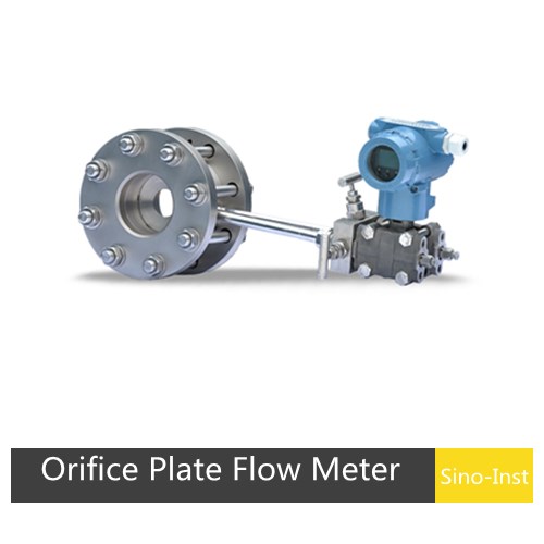
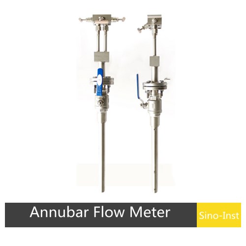
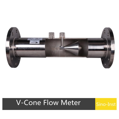
Also known as a DP flowmeter, it consists of a flow sensor and a pressure/differential pressure transmitter. It can be configured with a variety of restrictive elements, such as orifice plates, venturi tubes, wedges, V-cones, and Annubars. Differential pressure (DP) flowmeters are suitable for water, gas, steam, oil, and other applications.
Types of Inline Compressed Air Flow Meters
In summary, inline compressed air flow meters mainly fall into four categories: thermal mass flow meters, vortex flow meters, metal rotor flow meters, and differential pressure flow meters.
Thermal mass flow meters provide direct SCFM readings without pressure/temperature compensation. Vortex and DP-based meters provide volumetric flow and require T/P compensation for mass flow. Rotary meters are the cheapest option but only for local visual indication.
Type
Working Principle
Accuracy
Turndown
Pipe Size
Pressure Loss
Straight Pipe (U/D)
T/P Compensation
Output
Best For Compressed Air
Thermal Mass
Heat dissipation from heated sensor measures mass flow directly
±1–1.5% of reading
100:01:00
DN15–DN300
Very low (<0.5 kPa)
15D / 5D
Not required (direct mass)
4–20 mA, pulse, Modbus, HART
Best overall — direct SCFM, low leak detection, energy audits
Vortex
Karman vortex shedding frequency ∝ velocity
±1% of reading
30:01:00
DN15–DN300
Medium (5–15 kPa)
20D / 5D
Required (external T/P) or built-in (SI-3305)
4–20 mA, pulse, HART
Medium–high flow, steam-capable, wide temperature
Metal Rotameter
Float rises in tapered tube; flow ∝ float position
±1.6–2.5% of FS
10:01
DN15–DN200
Low–medium
5D / 2D
Required (scale is fixed-condition)
Local dial (+ optional 4–20 mA/HART)
Cheapest option, local visual indication only, small branch lines
Orifice Plate (DP)
Pressure drop across orifice ∝ (flow)²
±1–2% of FS
3:1–4:1
DN50–DN2000
High (10–50 kPa)
10D / 5D
Required
4–20 mA (via DP transmitter)
Legacy systems, very large pipes, established instrumentation
Averaging Pitot (Annubar/Verabar)
Multi-port pitot averages velocity across pipe
±1–1.5% of reading
10:01
DN50–DN9000
Very low (<1 kPa)
7D / 3D
Required
4–20 mA (via DP transmitter)
Very large air mains where low pressure loss matters
The choice between an insertion flow meter and an inline flow meter is primarily based on two factors: 1. Pipe diameter. 2. Accuracy requirements.
First, for small pipe diameters, DN2~DN200, inline flow meters are suitable. Installation is simpler on these pipes. For pipe diameters larger than DN200, insertion flow meters are a better choice due to installation difficulty and cost considerations.
Secondly, the required measurement accuracy must be considered. Inline flow meters, installed inside the pipeline, achieve maximum measurement accuracy. Insertion flow meters typically have lower accuracy than inline flow meters.
How to Measure Compressed Air Flow
To measure compressed air flow, install an inline flow meter sized to your pipe and flow range, choose the correct flow unit (SCFM for cost/energy reporting, ACFM for physical pipe velocity, Nm³/h for SI reporting), and add pressure and temperature compensation if the meter doesn’t read mass flow directly.
Thermal mass meters output SCFM without compensation; vortex, DP, and rotameter meters all need a pressure and temperature input to convert volumetric flow into mass flow.
Mass flow measures how much air (in kg/h or lb/min) moves through the pipe. Volumetric flow measures how much space (in m³/h or CFM) that air occupies. For compressed air, mass flow is what you pay for — every kilogram of air cost electricity to compress.
Mass flow is the only reading that tells you the truth about compressor performance and leak rates.
MFC vs MFM — what’s the difference?
MFM (Mass Flow Meter): measures and outputs mass flow. Passive device.
MFC (Mass Flow Controller): measures mass flow and adjusts an internal valve to hold a target setpoint. Active device.
For leak detection, energy audits, and compressor monitoring, you want an MFM (most compressed air applications). For blending gases or dosing air into a reactor at a fixed rate, you want an MFC. Our thermal mass meters are MFMs — they report flow but don’t control it. If you need closed-loop flow control, you can check out MFC.
Pressure & Temperature Compensation — When You Need It
Whether you need P&T compensation depends on which meter technology you chose:
Meter Type
T/P Compensation
Why
Thermal Mass
❌ Not needed
Measures mass flow directly from heat transfer
Vortex
✅ External required
Vortex frequency ∝ velocity, not mass
Precession Vortex
✅ Built-in
Integrated P and T sensors, auto-compensates
Metal Rotameter
✅ Required (fixed scale)
Scale is calibrated to one pressure/temperature
Orifice Plate / Annubar / V-Cone
✅ External required
DP is proportional to density × velocity²
How to Select the Right Inline Air Flow Meter
Based on our previous introduction, choosing a suitable Inline Air Flow Meter mainly requires you to check and confirm the following:
Pipe diameter: Determines whether you can choose inline or insert flow meter.
Flow range
Pressure rating: It’s best to confirm the pipe’s pressure resistance and operating pressure.
Temperature
Signal output requirements
Measurement accuracy requirements
Confirm the flow meter type: You can contact our sales engineers directly for matching.
Applications of Inline Compressed Air Flow Meters
Four applications usually pay back the meter within 12 months: leak detection, cost allocation between departments, compressor efficiency tracking, and metering N₂/O₂ on shared piping.
1. Compressed Air Leak Detection
US plants typically lose 20–30% of compressed air to leaks. Log flow on a weekend-night baseline — whatever SCFM the meter still reads is 100% leak loss. 45 SCFM leaking = roughly $14,000/year at $0.10/kWh. SI-3501 thermal mass is the right choice: 100:1 turndown catches both low overnight leak flow and full-production peak.
2. Energy Cost Allocation
Compressed air costs about $0.25–$0.35 per 1,000 SCF at US industrial rates. One SI-3501 or SI-3502 per branch line gives finance defensible numbers to split the compressor bill by department. A 250 SCFM department running 4,000 hr/yr = ~$18,000/year chargeback instead of plant overhead.
3. Compressor Efficiency Tracking
Healthy rotary screws deliver 4.0–4.5 SCFM per HP. When it drops to 3.2, air end or inlet valve wear is costing you money. Install an SI-3301 vortex on each compressor discharge, log SCFM÷kW monthly — when the ratio slips 15% below baseline, schedule service before catastrophic failure.
4. Nitrogen, O₂, and Other Gas Flow
Same meters work on N₂, O₂, and CO₂ if the gas factor is set at the factory. Thermal mass (SI-3501) needs a gas-specific calibration curve loaded during manufacture — you cannot switch gases in the field. Vortex (SI-3301) is gas-agnostic (same K-factor for air/N₂/O₂) but still needs P&T for mass output. For O₂ service we ship an oil-free, degreased version. See the nitrogen flow meter guide for N₂ generator sizing.
FAQ
Thermal (SI-3501) wins on cost, turndown, and SCFM-without-pressure — best for 2″–4″ headers and clean dry air. Vortex (SI-3301) wins on longevity and large pipes (DN150+) or wet/dirty gas. See the selection guide decision matrix.
12 months for billing/custody, 24 months for process monitoring, plus after any oil or water contamination event. Sino-Inst factory re-cal with NIST-traceable cert in 10 business days; 5-point field-verification service also available.
Yes. Log weekend-night baseline SCFM with production off — whatever shows up is 100% leak loss. Most US plants find 20–30% leak rate the first time. SI-3501 thermal mass is best for this: 100:1 turndown reads both small overnight leaks and full-load flow accurately.
Thermal mass — no. It measures mass directly. Vortex — yes for SCFM output (SI-3305 has P/T built in). Orifice/Pitot — always, paired with DP + P + T transmitters. Forgetting pressure on a vortex order is the #1 spec mistake.
Use SCFM for billing, sizing, and energy reporting — it’s referenced to 14.7 PSIA/68°F and independent of line pressure. Use ACFM only for local velocity or duct design. Thermal mass outputs SCFM natively; vortex/orifice compute it from onboard P/T. Full guide.
Yes — with correct gas factor set at the factory. Thermal mass (SI-3501) needs a gas-specific calibration curve (cannot switch in field). Vortex (SI-3301) is gas-agnostic but still needs P&T for mass output. For O₂: we ship degreased, oil-free.
Thermal mass ±1–1.5% of reading, vortex ±1%, metal rotameter ±1.5–2.5% of FS, orifice ±1–2% of reading. For billing/custody transfer use ±1%-of-reading tech (thermal or vortex). SI-3501 ships with individual NIST-traceable calibration certificate.
Compressed air flow meter price
The price of Compressed air flow meters are decided by flollowing factors:
Pipe diameter;
Flow range;
Measured medium;
Whether it is corrosive;
Whether explosion protection is required;
Whether it needs local display;
Connection method;
Measure pressure;
Measure temperature;
Signal output;
Accuracy requirements;
Material requirements;
These factors are more or less related to each other. Example – the cost of flow meters increases with accuracy and lifetime quality.
Thermal Mass Flow Meters and thermal mass flow controllers are suitable for most gaseous media. If a gas mass flow controller or thermal mass flow meter is factory-calibrated for one gas, but you want to switch to another, then a…
Analog gas flow meters specifically refer to a type of flow meter that outputs analog signals. The main function of a flow meter is to measure volumetric flow rate or mass flow rate and convert it into an electrical signal…
A rotameter, also known as a variable area flow meter, is widely used to measure the flow rate of various gases, especially in situations where no power supply is available. Whether measuring air, oxygen, nitrogen, carbon dioxide (CO2), or other…
There are more than a dozen categories and hundreds of models of flow meters on the market, all claiming to have unique measurement advantages. So how do you choose the flow meter that meets your needs? Simply put, start with…
The accurate flow measurement of oxygen is a foundational requirement across numerous industrial, medical, and scientific domains. Here, we’ll explore the principles and practices of selecting the right Industrial Oxygen Flow Meters. We’ll analyze gaseous and liquid oxygen, as well…
The selection of an appropriate variable area flow meter, commonly known as a rotameter, represents a foundational decision in numerous industrial and laboratory settings. This process demands a nuanced consideration of multiple interacting factors, extending beyond simple flow rate measurement…
Accurate flow measurement is crucial for process control. Before purchasing a flow meter, you should consider the installation requirements. The meter’s installation location and the length of upstream and downstream straight pipe runs directly affect the accuracy of the measurement…
Slurry and sludge flow measurement is complex and challenging. Accurately measuring slurry flow can improve efficiency and reduce costs in industries such as wastewater treatment, water conservancy projects, river dredging, and oil well cementing. Slurry flow meters measure the volumetric…
Zhang Wei, possesses 20 years of experience as an automation instrumentation engineer, specializing in the research, design, installation, commissioning, and maintenance of automation instruments.
Face to various instrument communication protocols (such as Modbus, Profibus, etc.), with solid hardware circuit design and software programming skills (proficient in C language and PLC programming). Has extensive project experience; projects he has led and participated in have all achieved outstanding results, improving product accuracy, reducing costs, and increasing production efficiency.
Possesses excellent communication and coordination skills and a strong team spirit, enabling him to quickly respond to customer needs and provide high-quality automation instrumentation solutions.