
Paddle Flow Switch Technical and Selection Guide
What Is a Paddle Flow Switch?
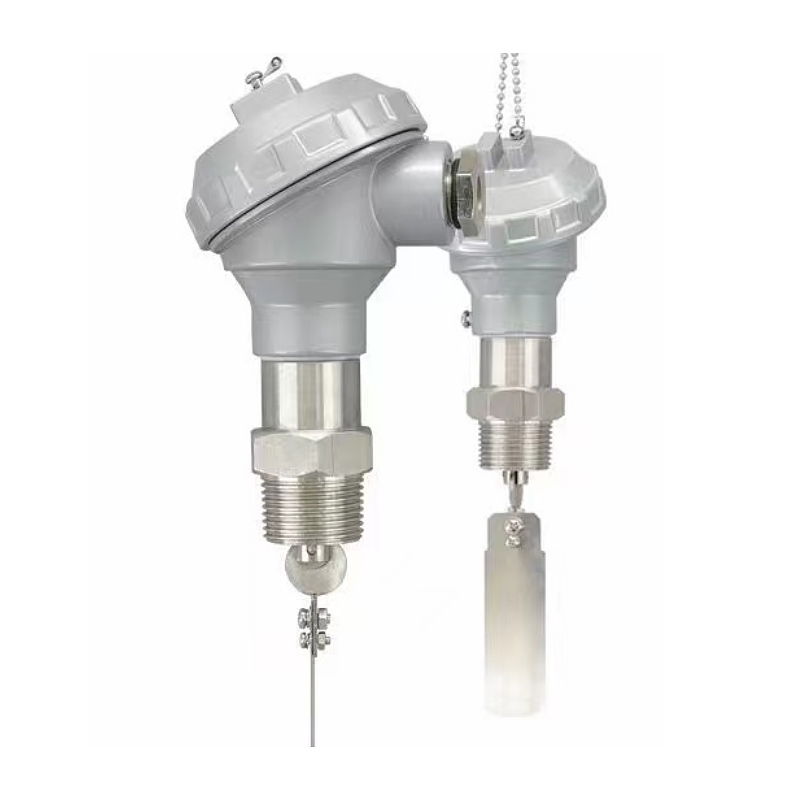
A paddle flow switch is a mechanical flow switch that uses a paddle to detect unidirectional or bidirectional flow of clean media such as air, oil, or water. It is also known as a vane, target, or baffle flow switch. The medium being measured must not contain any entangling debris. Precise on/off settings are achieved via a knob, and the mechanical and electronic components are completely isolated from one another.
With paddles of various sizes available, users can flexibly combine them based on on-site
conditions when dealing with large pipe diameters and low flow rates or when the pipe is not fully filled. It is widely used in industrial automation, water treatment, HVAC, and petrochemical fields.
Recommended Paddle Flow Switches
The models below cover most paddle flow switch applications. Send us the medium, pipe size and the flow at which the switch must trip, and we will match the paddle and factory-set the setpoint.

SI-01B Target Flow Switch
Insertion paddle switch for 1″–6″ pipe with 1#, 2# and 3# paddles. Setpoint 20–1,800 L/min (water), 1.6 MPa, 0–90 °C, SPDT contact rated 250 VAC 10 A.

SI-01BS Explosion-proof Flow Switch
Stainless steel paddle switch certified Ex ia IIC T6 Ga for hazardous areas. Rated 25 bar, media up to 250 °C, repeatability ±2.5% of full range.

SI-600 Thermal Dispersion Flow Switch
No moving parts, so it suits media with debris that could jam a paddle. Water 1–150 cm/s, air 20–2,000 cm/s, 100 bar, PNP/NPN or relay output.
Working Principle of the Paddle Flow Switch
In a paddle flow switch, the fluid pushes the paddle to deflect, which in turn activates a microswitch, converting mechanical motion into an electrical signal to monitor and control flow.
The core components of a paddle flow switch are: the paddle (blade), the shaft and reset mechanism, the magnetic coupling system and reed switch, and the housing with terminal blocks.
When fluid flows through the pipe, the vane deflects. By adjusting the set screw, the single-pole double-throw microswitch is set to activate at the preset flow rate, outputting a switch signal. During bidirectional detection, the deflection of the vane pushes the magnetic module upward, driving the switch module to activate.
Used to detect unidirectional flow of air and water; the water must be free of entangling debris. When the fluid flows through the pipe in the indicated direction, the vane deflects. By adjusting the set screw, the single-pole double-throw micro-switch is set to actuate at the preset flow rate, outputting a switch signal. With a wide preset flow range and convenient adjustment, it can be used to measure media such as water, gas, and oil.
1. No-flow condition: In a stationary fluid, the baffle (typically spring-loaded) remains in its initial position, and the micro-switch is in the normally open (NO) or normally closed (NC) state (depending on the setting).
2. Flow condition: When the fluid begins to flow and reaches the set minimum flow velocity, the fluid’s impact force overcomes the spring’s resistance, causing the baffle to deflect.
3. Trigger Signal: The deflection of the paddle moves an internal linkage, actuating the microswitch and changing the circuit’s on/off state (e.g., from open to closed), thereby sending a “normal flow” or “low/high flow” signal to the control system.
4. Reset: When the flow velocity falls below the set value, the spring force pushes the paddle back to its original position, and the switch resets.
Paddle vs Target vs Piston vs Thermal Flow Switch
| Item | Paddle | Target (cone & disc) | Piston | Thermal dispersion |
| Sino-Inst model | SI-01B; SI-01BS (explosion-proof, Ex ia IIC T6 Ga) | SI-FS | SI-80, SI-210 | SI-600, SI-300C |
| Sensing principle | Flow deflects the paddle; a mechanical linkage trips the micro switch on top | Flow pushes the disc inside a conical measuring tube; magnetic coupling drives the pointer and alarm point | Flow moves a spring-loaded magnetic piston that actuates an external reed switch | Flow carries heat away from a heated resistor; compared with an unheated reference resistor |
| Installation | Insertion | In-line | In-line | Insertion |
| Connection / pipe size | SI-01B: 1/2″, 3/4″, 1″ thread; SI-01BS: R1″ thread; for 1″–6″ pipe | DN15–DN250 (FS-1 thread 3/4″–2″; FS-2/3/4 flanged) | G1/4–G1 | One model fits multiple pipe sizes |
| Setting range | 20–1,800 L/min (water, by pipe size and paddle no.); SI-01BS low-flow version for DN25/DN50: 0.26–1.68 L/min | See flow table of each model | SI-80: 0.4–60 L/min; SI-210: 0.6–70 L/min (actuation point, water) | Water 1–150 cm/s; oil 3–300 cm/s; air 20–2,000 cm/s |
| Pressure rating | SI-01B: 1.6 MPa; SI-01BS: 25 bar | 0.6–4.0 MPa (higher pressure optional) | SI-80: 200 bar stainless steel / 100 bar brass; SI-210: 100 bar stainless steel / 50 bar aluminum | 100 bar |
| Media temperature | SI-01B: 0–90 °C; SI-01BS: ≤250 °C | Standard 85 °C; high-temperature type 300 °C | Max. 90 °C | SI-600: -20–80 °C; SI-300C: -20–90 °C; custom -40–150 °C |
| Accuracy / repeatability | SI-01B: switching differential 8–80 L/min by pipe size; SI-01BS: repeatability ±2.5% of full range | Accuracy 12%; repeatability ±2.5% | SI-80: repeatability ±3% of full range; SI-210: accuracy ±5% of full range | Repeatability ±2% (SI-600); response time 1–13 s, typical 2 s |
| Output | SPDT micro switch (NO + NC); SI-01B contact rating 250 VAC 10 A | 1 or 2 alarm points; transistor relay (intrinsically safe) available | Reed switch, 24 VDC/250 VAC; SI-80 1.5 A, SI-210 100 mA | PNP, NPN, SPDT relay; 4–20 mA optional |
| Local indication | None | Pointer dial with flow scale | SI-80: pointer; SI-210: setting scale + LED status | 6-LED flow status bar |
| Media | Gas and liquids (water, oil) | Liquids | Liquids and gases | Water, oil, air (gas and liquid) |
| Pressure loss | SI-01BS: 0.08 bar at max. flow | Low-resistance streamlined design | Approx. 0.3 bar at 25 L/min | Very low |
| Moving parts | Yes | Yes | Yes | None |
| Setpoint adjustment | Adjusting screw; factory-set near minimum flow | Move the alarm pointer without stopping flow | Set by scale / slide the switch housing | Potentiometer, set at actual flow |
| Best fit | Flow/no-flow protection on cooling water, lube oil and gas lines in 1″–6″ pipe; SI-01BS for hazardous areas | Process lines needing both a visible flow reading and an alarm; high-temperature service | Low flow in small lines; high-pressure systems | Varying pipe sizes, gas or liquid, maintenance-free sites |
How to Size the Paddle
Based on our experience with flow control, you can refer to the following methods:
1. Refer to the cross-reference table of pipe diameters and paddle numbers
| Pipe size | Paddle no. | Setpoint adjustment range (L/min) | Switching differential (L/min) | Repeatability error (L/min) |
| 1″ | 1# | 20–48 | 8 | 1.1 |
| 1-1/4″ | 1# | 34–100 | 10 | 2.6 |
| 1-1/2″ | 1# | 65–160 | 14 | 3.8 |
| 2″ | 1# | 120–280 | 26 | 6.4 |
| 2-1/2″* | 1# | 210–550 | 18 | |
| 3″* | 1# | 380–750 | 20 | |
| 2″ | 2# | 40–140 | 18 | 4 |
| 2-1/2″* | 2# | 110–340 | 15 | |
| 3″* | 2# | 180–470 | 18 | |
| 4″* | 2# | 350–920 | 20 | |
| 3″* | 3# | 115–220 | 20 | |
| 4″* | 3# | 210–590 | 20 | |
| 5″* | 3# | 380–1200 | 40 | |
| 6″* | 3# | 550–1800 | 80 |
Notes:
- Rows marked * are reference values.
- Setpoint adjustment range is the adjustable range of the lower switching point, i.e. the flow rate at which the contacts switch when flow decreases.
- Paddles 4# and 5# can be used for larger pipe sizes.
2. Cutting guidelines.
The paddle is removable, and you can select different paddles based on the actual installation conditions. If a target plate of the appropriate length is not available, a slightly longer one can be trimmed to size. However, the target plate must not be installed too short; if it is too short, it will affect the switch’s sensitivity and, in severe cases, may prevent the switch from operating.
3. Stacking Multiple Target Plates
During normal use, the target plate is subjected to water flow pressure. If it is exposed to excessive flow velocity for an extended period, causing severe bending or deformation, it is prone to fatigue failure. In such cases, the flow velocity can be reduced by increasing the pipe size to ensure the paddle-type flow switch operates normally. Additionally, when using long paddle plates in larger-diameter pipes, since a single long paddle plate often fails to meet the required stiffness—which can lead to failure—the paddle plates must be installed in a stacked configuration, with the longest paddle plate positioned at the front.
Paddle Flow Switch Selection Guide
When selecting a paddle-type flow switch, the following parameters must be confirmed:
- Medium Type:
Water (general/corrosive), oil, gas (compressed air/natural gas). Different media have varying densities and viscosities, requiring different trigger forces.
For viscous media, please specify the viscosity, temperature, and medium type.
For gaseous media, please specify the pressure (gauge pressure/absolute pressure), temperature, and medium type. - Pipe Diameter (DN):
Must match the pipe diameter (e.g., DN15, DN20, DN25…DN100, etc.). Note whether the connection is threaded or flanged. - Flow Range:
Determine the activation flow rate (Flow to Activate) and reset flow rate (Flow to Reset). Different manufacturers have different flow curves for different pipe diameters. - Pressure Rating:
Maximum operating pressure (10 bar, 16 bar, etc.), which must exceed the system’s operating pressure. - Temperature Range:
Medium temperature (e.g., -10°C to +80°C or higher), which determines the seal and housing materials. - Electrical Parameters:
Contact rating (e.g., AC 220 V, 10 A), voltage rating, and protection rating (IP65/IP67). - Flow Direction:
When ordering, specify the direction of medium flow—whether unidirectional or bidirectional. Butterfly valves have clear flow direction arrows; ensure the fluid flows in the correct direction during installation. - Adjustment Function:
Whether it features an adjustable spring, allowing sensitivity to be adjusted within a certain range.
Set the Flow Setpoint
This section covers the direction of the adjustment screw, rising and falling setpoints, hysteresis, and the rule of thumb: “Set to X% of the minimum normal flow rate.”
Generally, our flow switches are shipped with the flow setpoint already configured according to the user’s requirements. Of course, users can also adjust the flow setpoint on-site.
1. Direction of the Adjustment Screw and Factory Settings
Turning clockwise increases the setpoint (requiring a higher flow rate to activate); turning counterclockwise decreases the setpoint.
The factory setting is typically at the minimum flow rate. To check this, repeatedly press the main lever; if you do not hear a “click” when it returns to its original position, the setting is below the factory minimum and must be adjusted clockwise to restore it.
2. Rise and Fall: Activation and Reset Points
The adjustment range in our table refers to the lower switching value—that is, the cut-off point when flow decreases. The make-contact point during flow increase is equal to the lower switching value plus the switching differential.
For example, for a 1″ pipe and Target No. 1, if the cut-off point is set at 20 L/min, the flow must rise to approximately 28 L/min before the circuit re-engages.
3. What Percentage of Normal Flow Should the Setpoint Be?
For air-cooled module installations, the recommended cut-off flow rate is generally 65% of the rated flow rate. If the flow rate falls below this value, the switch must open, triggering a unit protection alarm; the reliability of the flow switch must be verified before startup.
The cut-off point on the chilled water side is typically set between 50% and 65% of the rated flow rate, while on the cooling water side, it is approximately 70%. The specific setting should be based on the minimum flow rate specified by the original equipment manufacturer (OEM), and the switch’s cut-off point should be set slightly higher than the unit’s minimum flow rate.
4. On-Site Factors Affecting the Setting
Vertical Pipes: Baffle-type flow switches may be installed on vertical pipes with upward flow; however, due to the effects of gravity, the set point must be adjusted to a value slightly higher than the standard. They must not be installed on pipes with downward flow.
Bubble-Induced Flickering: When air is mixed into the cooling water, bubbles can cause the target plate to reset instantly, leading to false alarms and shutdowns. It is recommended to install a time-delay relay.
Pump Shutdown Backflow Surge: The backflow surge that occurs when the pump stops can cause fatigue damage to the target plate; a check valve can be installed downstream.
Related Guides

Flow Switches for Industrial Applications
How thermal, paddle and piston flow switches work, and which type to choose for water, oil and gas lines.
Thermal Dispersion Flow Switches: A Complete Guide
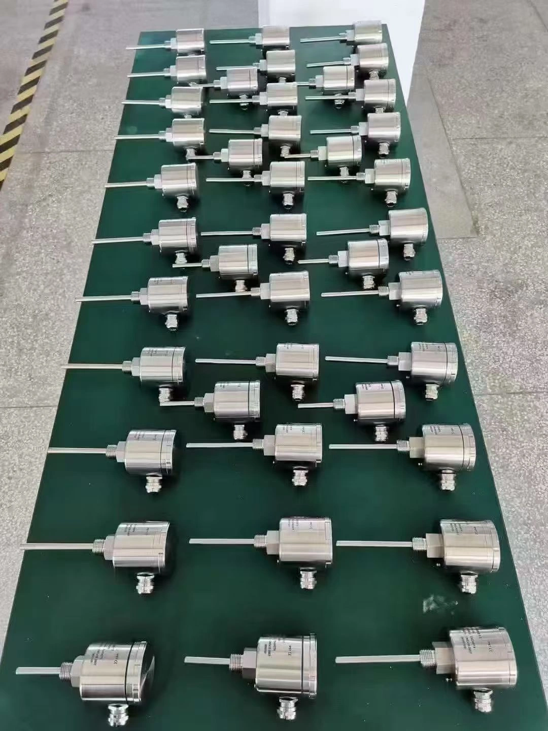
No moving parts to jam. The alternative when the medium carries fibers or debris that would foul a paddle.

Flowmeter Installation: Straight Run Requirements
Upstream and downstream straight pipe lengths by device type, and what to do when the run is too short.

Zhang Wei, possesses 20 years of experience as an automation instrumentation engineer, specializing in the research, design, installation, commissioning, and maintenance of automation instruments.
Face to various instrument communication protocols (such as Modbus, Profibus, etc.), with solid hardware circuit design and software programming skills (proficient in C language and PLC programming). Has extensive project experience; projects he has led and participated in have all achieved outstanding results, improving product accuracy, reducing costs, and increasing production efficiency.
Possesses excellent communication and coordination skills and a strong team spirit, enabling him to quickly respond to customer needs and provide high-quality automation instrumentation solutions.
Want to see more of our engineering guides in Google Search? Add Sino-Inst as a preferred source.