
Digital Pressure Gauges with Output
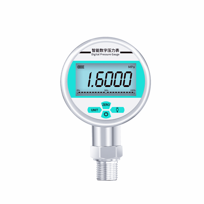
Digital Pressure Gauges with Output support real-time local pressure indication and offer optional 4-20 mA or RS485 outputs. These digital pressure gauges provide electronic readings for gauge, absolute, vacuum and compound (vacuum-pressure) ranges, from -100 kPa (about -29.5 inHg) up to 160 MPa. Sino-Inst’s digital pressure gauges are equipped with a 5-digit LCD display and can measure gases, liquids, oils, and other media that do not corrode stainless steel. They feature a variety of functions, including zeroing, backlight, power on/off, unit conversion, low-voltage alarm, and peak recording, making them easy to operate and convenient to install.
USD 180.00/pc for ranges up to 60 MPa with ±0.4% or ±1.0% FS accuracy. High-accuracy (±0.2% FS) and high-pressure (above 60 MPa) versions are quoted on request.
Benefits
Technical Specifications
Our SI-80A smart digital pressure gauge covers vacuum, gauge, absolute and compound ranges from -100 kPa up to 160 MPa, with ±0.2%, ±0.4% or ±1.0% FS accuracy and a 316L stainless steel wetted sensor.
Performance Specifications
| Parameter | Specification |
|---|---|
| Pressure type | Gauge, absolute, vacuum (negative) and compound |
| Vacuum range | 0 to -1 kPa … 0 to -100 kPa (-14.5 psi) |
| Gauge range | 0–1 kPa … 0–160 MPa (0–23,200 psi) |
| Absolute range | 0–50 kPa … 0–3.5 MPa abs (0–508 psia) |
| Compound range | -1 to +1 kPa … -100 kPa to +20 MPa |
| Accuracy | ±0.2% FS, ±0.4% FS or ±1.0% FS |
| Long-term stability | ≤ ±0.2% FS per year |
| Overload pressure | 200% FS (range ≤ 10 MPa); 150% FS (range > 10 MPa) |
| Compensated temperature | -10 to +60 °C (14 to 140 °F) |
| Ambient temperature | -40 to +85 °C (-40 to 185 °F) |
| Media temperature | -40 to +85 °C (-40 to 185 °F), For high-temperature versions, please contact us for customization. |
| Response time | ≤ 1 s |
Electrical and Display
| Parameter | Specification |
|---|---|
| Power supply | 3 V battery (2 × AAA); 24 VDC (9–24 VDC); 220 VAC; 380 VAC |
| Battery life | Up to 24 months (battery version, no analog output) |
| Output | 4–20 mA, 2-wire loop powered (24 VDC); RS485, 4-wire (power + A/B) |
| Insulation resistance | 100 MΩ at 500 VDC |
| Electrical protection | Reverse polarity protection, EMI resistant |
| Display | 5-digit LCD, blue backlight (white on some versions) |
| Functions | On/off, backlight, zero, unit switching, peak hold, low-battery alarm, field calibration |
| Electrical connection | Direct cable (1 m standard), aviation connector, or custom |
| Hazardous area | Intrinsically safe version available |
Mechanical Specifications
| Parameter | Specification |
|---|---|
| Dial size | 60 mm, 80 mm or 100 mm (2.5″, 3″, 4″) |
| Mounting | Bottom (radial) or back (axial) connection |
| Wetted parts | 316L stainless steel |
| Housing | 304 stainless steel |
| Process connection | M20×1.5, G1/2, G1/4, 3/8″ NPT, 1/4″ NPT male; flush diaphragm, tri-clamp or flange on request |
| Compatible media | Gases, liquids and oils compatible with 316L stainless steel |
| Weight | Approx. 0.5 kg (1.1 lb) |
Featured Applications
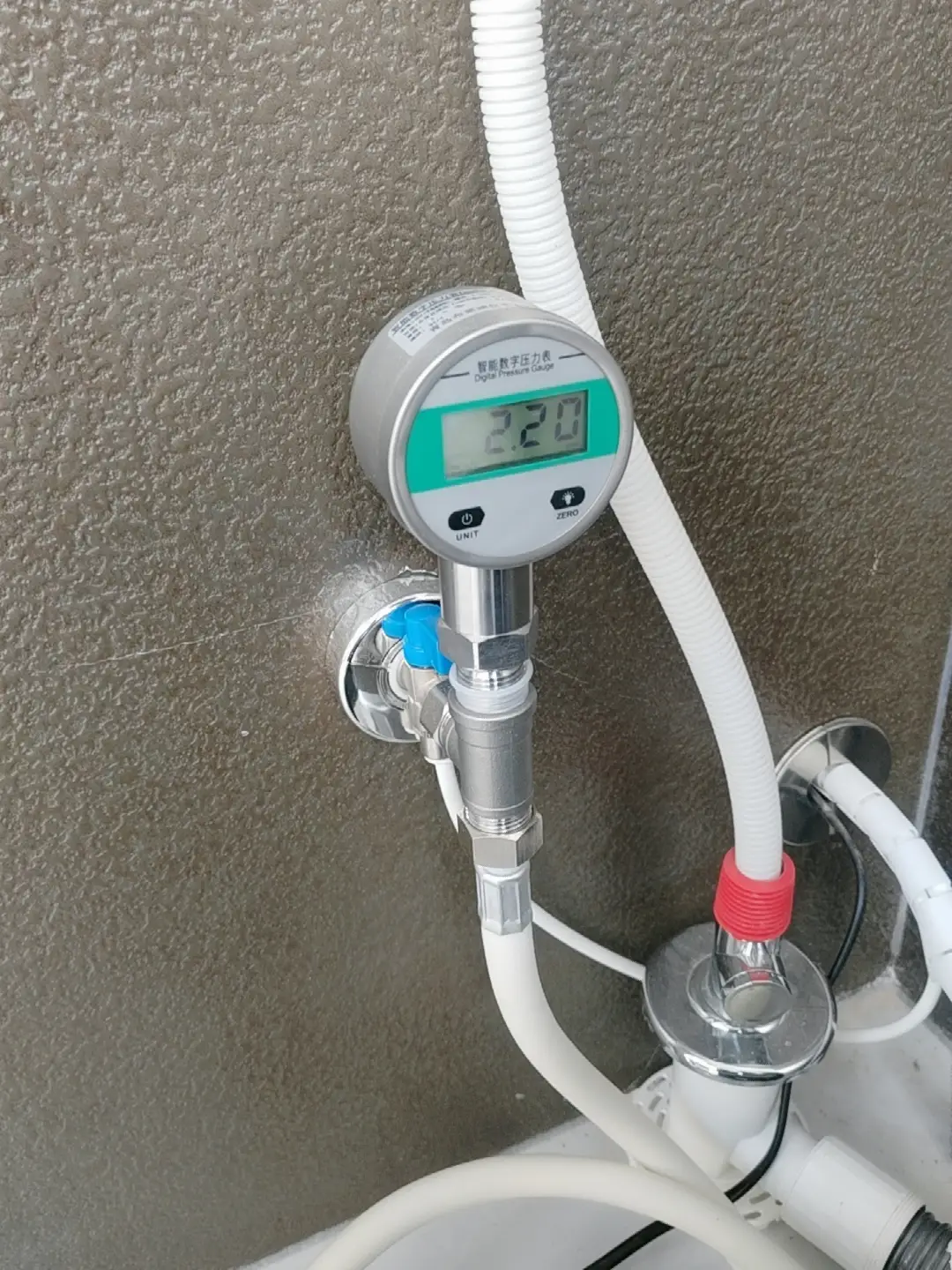
Digital pressure gauges display pressure on-site while transmitting signals via 4–20 mA or RS-485 to a PLC, DCS, or monitoring system, making them suitable for measurement points that require both local readings and remote monitoring.
1. Industrial Automation and Hydraulics/Pneumatics
Common installation locations include air supply pressure points on production lines, pneumatic circuits in stamping and assembly equipment, and hydraulic power units for machine tools. If the pressure deviates from the set value, the control system can immediately trigger an alarm or shut down the machine to prevent the production of defective products in batches. For hydraulic systems, pressures of 0–17 MPa or 0–35 MPa are typically selected, while 0–1 MPa is sufficient for pneumatic circuits.
2. Energy Industry
In power plants, these gauges are primarily used to measure lubricating oil pressure and auxiliary equipment cooling water pressure; in oil and gas fields, they are used to measure wellhead pressure and transmission pipeline pressure. Data is transmitted to the central control room, allowing operators to monitor pressure changes without having to conduct on-site inspections. For high-pressure wellheads, ranges from 0–60 MPa to 0–160 MPa are available; intrinsically safe models must be selected for hazardous areas; when the medium temperature exceeds 85 °C, a condensing elbow or heat sink must be installed upstream of the gauge.
3. Water Supply and Wastewater Treatment
Water pressure monitoring is required at pump station outlets, pipeline network nodes, lift pump outlets, and before and after filters. Water utilities adjust pump operation based on pressure at these points; pressure changes immediately indicate pipeline leaks or filter blockages. For municipal water supply, a range of 0–1 MPa is generally selected; if negative pressure may occur at the pump suction end, a compound range gauge should be selected.
4. HVAC and Central Heating
In central air conditioning and heating systems, pressure is primarily measured at the supply and return lines of chilled water, cooling water, and circulating hot water, as well as at make-up water pressure-stabilization points. Pressure signals can be used directly to control variable-frequency pumps, allowing for timely pressure relief when pressure is too high and timely water replenishment when it is too low. For water systems, a range of 0–1 MPa or 0–1.6 MPa is generally selected; if measuring refrigerant, first confirm that the medium is compatible with 316L stainless steel.
5. Petrochemical Industry
These sensors are used in reactors, distillation columns, process piping, storage tanks, and oil transmission pipelines. On-site personnel can read the gauges directly, while the signals are fed into the DCS for process control and overpressure alarms. When selecting a model, first confirm whether the medium is corrosive to 316L stainless steel; choose intrinsically safe models for flammable and explosive environments; and select negative pressure or absolute pressure ranges when measuring vacuum or absolute pressure.
6. Food and Beverage
Primarily used in the air supply and hydraulic systems of filling machines, sterilization equipment, fermenters, and CIP (Clean-in-Place) lines. Stable pressure ensures consistent filling volumes and sealing quality, and pressure records facilitate production traceability. For all measurement points in direct contact with the product, it is recommended to select flush-diaphragm or clamp connections (process connection code M6) rather than standard threaded connections to avoid creating cleaning dead zones.
7. Laboratory and Test Equipment
Suitable for use on reactors, pressure test benches, environmental simulation devices, and calibration equipment. With an accuracy of ±0.2% FS, these gauges can replace precision dial pressure gauges as standard reference instruments; models with remote output can be connected to data acquisition systems to automatically record pressure curves. When used for calibration, it is recommended to order calibration data (Option C) at the same time.
Ordering Code
Build the part number by selecting one code from each group in order: SI-80A – Dial – Range – Process Connection – Electrical Connection – Power – Output – Accuracy – Mounting – Options.
| Group | Code | Description |
|---|---|---|
| Dial size | H | 100 mm (4″) |
| E | 80 mm (3″) | |
| S | 60 mm (2.5″) | |
| Pressure range | 1–14, 99 | See range code table below |
| Process connection | M1 | M20×1.5 male |
| M2 | G1/4 male | |
| M3 | G1/2 male | |
| M4 | 3/8″ NPT male | |
| M5 | 1/4″ NPT male | |
| M6 | Custom (flush diaphragm, tri-clamp, flange, etc.) | |
| Electrical connection | J2 | Direct cable, 1 m standard |
| J3 | Aviation connector | |
| J6 | Custom | |
| Power supply | P6 | 3 V battery (2 × AAA) |
| P7 | 24 VDC | |
| P8 | 220 VAC | |
| P9 | 380 VAC | |
| Output | V4 | 4–20 mA, 2-wire |
| V6 | RS485 | |
| Accuracy | 2 | ±0.2% FS |
| 4 | ±0.4% FS | |
| 10 | ±1.0% FS | |
| Mounting | X | Radial (bottom connection) |
| Y | Axial (back connection) | |
| Options | I | Intrinsically safe |
| C | Calibration certificate | |
| Y | Custom |
Pressure Range Codes
| Type | Code | Range | psi | bar |
|---|---|---|---|---|
| G – Gauge | 1 | 0–100 kPa | 0–14.5 | 0–1 |
| 2 | 0–1 MPa | 0–145 | 0–10 | |
| 3 | 0–3.5 MPa | 0–508 | 0–35 | |
| 4 | 0–17 MPa | 0–2,466 | 0–170 | |
| 5 | 0–35 MPa | 0–5,076 | 0–350 | |
| 6 | 0–60 MPa | 0–8,702 | 0–600 | |
| 7 | 0–100 MPa | 0–14,504 | 0–1,000 | |
| 14 | 0–160 MPa | 0–23,206 | 0–1,600 | |
| A – Absolute | 8 | 0–100 kPa abs | 0–14.5 psia | 0–1 bar abs |
| 9 | 0–500 kPa abs | 0–72.5 psia | 0–5 bar abs | |
| 10 | 0–1 MPa abs | 0–145 psia | 0–10 bar abs | |
| 11 | 0–3.5 MPa abs | 0–508 psia | 0–35 bar abs | |
| L – Vacuum | 12 | -100–0 kPa | -14.5–0 (-29.5 inHg) | -1–0 |
| C – Compound | 13 | -100 to +20 kPa | -14.5 to +2.9 | -1 to +0.2 |
| Custom | 99 | Other ranges, including compound up to +20 MPa | — | — |
Ordering example: SI-80A-H-3-M1-J2-P7-V4-4-X-C = 100 mm dial, 0–3.5 MPa gauge, M20×1.5 male, 1 m cable, 24 VDC power, 4–20 mA output, ±0.4% FS, radial mount, with calibration certificate.
Notes: The 24 VDC 4–20 mA version is 2-wire loop powered and connects to a PLC or DCS analog input the same way as a standard transmitter; see our 2-wire, 3-wire and 4-wire wiring guide. The RS485 version uses four wires, two for power and two for A/B; our RS485 pressure sensors page covers bus wiring basics. The battery version (P6) is display-only. Confirm that the process media is compatible with 316L stainless steel. For ranges or connections not listed, select code 99 or M6 and state your requirement in the inquiry.
Digital Pressure Gauge or Pressure Transmitter?
Simply put, if a measurement point requires both on-site readings and data upload, choose a digital remote-read pressure gauge; if the signal needs PID control, HART configuration, or span adjustment, choose a pressure transmitter.
| Item | Digital Remote-Reading Pressure Gauge (SI-80A) | Pressure Transmitter |
| Design Highlights | Provides both local readings and remote signal transmission | Provides signals to a PLC/DCS |
| Display | Equipped with a large 60/80/100 mm LCD screen | No display, or optional small local indicator |
| Installation | Designed as a direct replacement for mechanical pressure gauges | Requires a separate mounting location |
| Wiring | 4–20 mA two-wire (24 VDC) — wired the same way as a standard transmitter; RS485 four-wire | Primarily 4–20 mA two-wire configuration |
| Power Supply | Power options: Battery-powered (display only), 24 VDC, 220 VAC, or 380 VAC | 24 VDC loop-powered |
| Communication | Output options: 4–20 mA or RS485 | Available with 4–20 mA, 0–10 V, or RS485 outputs; smart versions include HART protocol |
| Accuracy | Accuracy: ±0.2% / ±0.4% / ±1% FS | Typical accuracy: ±0.1% to ±0.5% of full scale (FS); smart versions: ±0.075% or better |
| Range Adjustment | Fixed measurement range | Smart versions allow for field-configurable range (re-ranging) |
If you currently have mechanical gauges installed and want to add remote monitoring points—such as at pump stations, air compressors, hydraulic stations, or heat exchange stations—switching to the SI-80A is the most convenient solution. There’s no need to modify the piping or install separate display instruments; a single gauge handles both local display and remote transmission.
If the signal needs to be used for precise PID control, or if you require HART configuration, span adjustment, or higher accuracy, choose a smart pressure transmitter.
Related Pressure Products
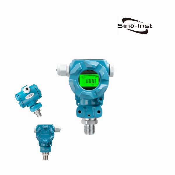
SI-2088 Industrial Pressure Transmitter
For points that feed a control loop and do not need a large local display.
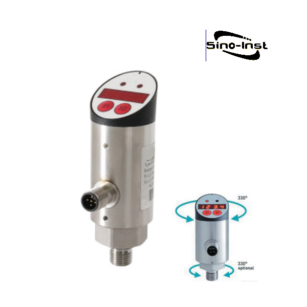
Electronic Pressure Switch with LED Display
Adds relay outputs when the point needs a pump start/stop or a high/low alarm.
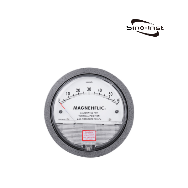
SI-D2000 Differential Pressure Gauge
Digital readout for filter, duct and pump differential pressure.
Further Reading
- Pressure Transmitter 4-20mA Guide: Testing and Troubleshooting: how to check the loop current once the gauge is wired to a PLC.
- G Thread vs NPT for Pressure Transmitters: which process connection to order (codes M1–M5).
- Vacuum and Negative Pressure Sensors: background for vacuum and compound range selection.
Zhang Wei, possesses 20 years of experience as an automation instrumentation engineer, specializing in the research, design, installation, commissioning, and maintenance of automation instruments.
Face to various instrument communication protocols (such as Modbus, Profibus, etc.), with solid hardware circuit design and software programming skills (proficient in C language and PLC programming). Has extensive project experience; projects he has led and participated in have all achieved outstanding results, improving product accuracy, reducing costs, and increasing production efficiency.
Possesses excellent communication and coordination skills and a strong team spirit, enabling him to quickly respond to customer needs and provide high-quality automation instrumentation solutions.