Paddle Wheel Flow Meters measure flow rate by using the mechanical kinetic energy of the fluid to rotate an impeller. They are an economical solution for industrial and laboratory flow measurement. Paddle Wheel Flow Meters are suitable for clean or slightly contaminated liquids, chemicals, water, and other liquids.
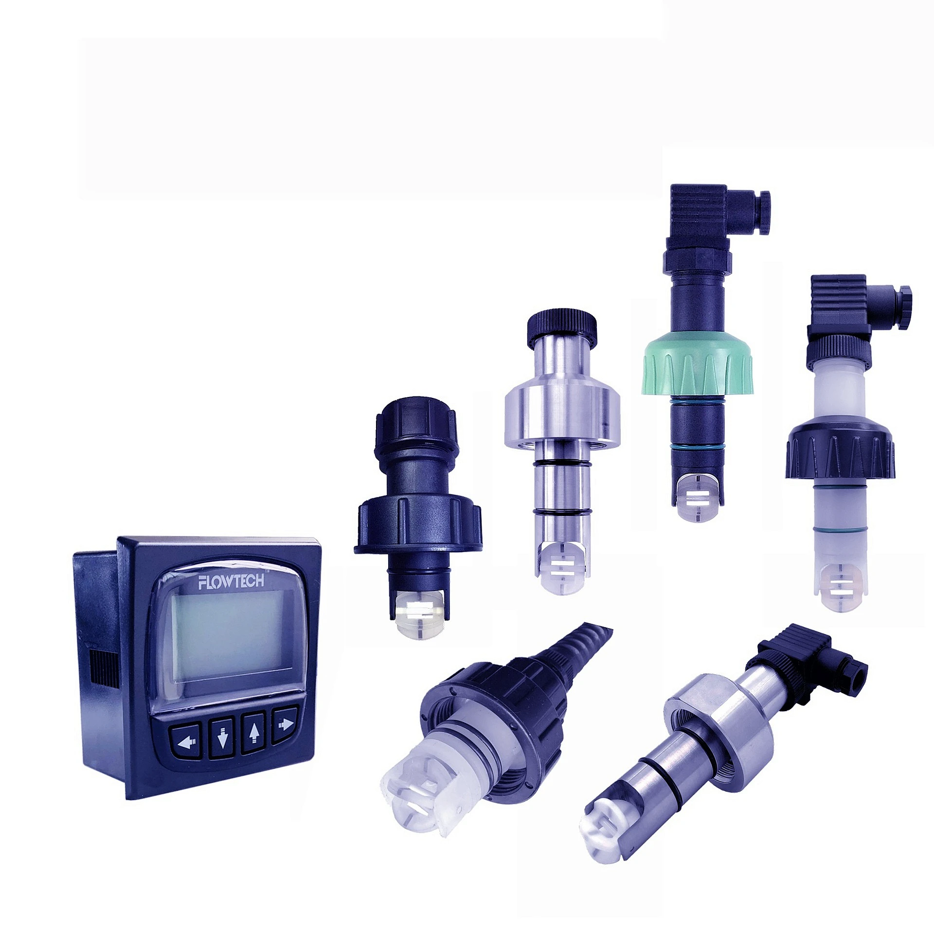
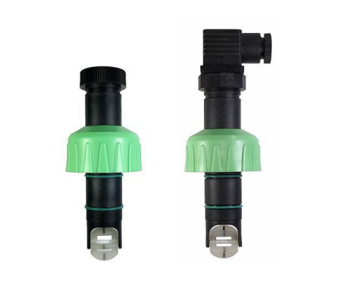
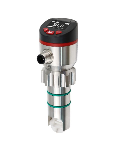
Sino-Inst supplies compact and corrosion-resistant models of Paddle Wheel Flow Meters. Maximum pressure 110 Bar, maximum temperature 100°C. Full-scale accuracy ±1%. Local compact display or a professional flow transmitter can be selected for flow display and signal output: 4-20mA, RS485, pulse.
Actual flow calibration, each unit undergoes strict factory testing.
Six-point calibration, calculates the average K value. Complies with national flow detection and measurement standards.
Signal output and display
Square wave pulse signal, switch/pulse/analog 4-20mA, RS485, etc., all customizable.
Integrated local display or separate display can be selected.
Paddle Wheel Flow Meter Working Principle
Paddlewheel flow meters utilize the mechanical kinetic energy of the fluid to rotate an impeller. Paddles on the rotor are inserted into the fluid flow, converting the kinetic energy of the fluid into rotational force, causing the rotor to rotate on a shaft. The faster the fluid flows, the faster the impeller rotates. The rotation of the shaft can be sensed mechanically or by detecting the movement of the paddles.
Paddle movement is typically detected magnetically; each paddle or embedded metal blade generates a magnetic pulse when it rotates near a magnetic block. More pulses are generated when the fluid flows faster. The transmitter can then process these pulse signals to determine the fluid flow rate.
Paddlewheel flow meters can also provide local or split-type flow rate displays and can be configured with pulse, switch, analog, and RS485 signal outputs. Sino-Inst’s Paddlewheel Flow Meters are ideal for measuring the flow rate of clean, low-viscosity liquids. Their simple design makes them cost-effective, easy to install, and easy to maintain.
Comparison of Paddle Wheel Flow Meters and Turbine Flow Meters
While both paddle wheel flow meters and turbine flow meters measure flow rate by rotating impellers, their structural approaches are completely different.
Paddle wheel flow meters are insertion type, with the impeller axis perpendicular to the pipe. Only a few edge blades are immersed in the fluid, measuring the local velocity near the pipe wall, which is then converted into the overall pipe flow rate. Turbine flow meters, on the other hand, are full-pipe type, with the rotor positioned along the pipe direction, allowing all fluid to pass through the center of the rotor. They measure the average flow rate across the entire cross-section. The former is like inserting a small waterwheel at an angle into a river, while the latter is more like letting the entire river flow through a water turbine.
The two differ significantly in accuracy. Paddle wheel flow meters are typically within ±1% to ±2%, heavily influenced by flow field distribution and installation location, and are sensitive to straight pipe sections before and after them. Turbine flow meters, after calibration, can achieve ±0.5% or even higher accuracy, with repeatability reaching ±0.1%, and a much wider range. Therefore, they are more commonly used in applications requiring trade settlement, such as oil and gas supply. The trade-off is that turbine-type flowmeters require high media cleanliness, typically necessitating filters; rotor bearings wear down, requiring regular calibration; and pressure loss is greater than rotary-type flowmeters.
Cost and pipe diameter are other key differences.
Rotary-type flowmeters are simple in structure, inexpensive, can be inserted under pressure, and are easy to install and disassemble. Their cost advantage becomes more pronounced with larger pipe diameters, making them popular for flow monitoring in tap water, irrigation, circulating water, and large building and industrial pipelines. Turbine-type flowmeters offer better cost-effectiveness for small to medium diameters, but costs increase significantly with larger diameters.
Choosing the right turbine-type flowmeter boils down to two things: accuracy requirements and pipe diameter. For limited budgets, thick pipes, and only flow trend monitoring, rotary-type flowmeters are sufficient; for high accuracy, metering and billing capabilities, and clean media, turbine-type flowmeters are the way to go.
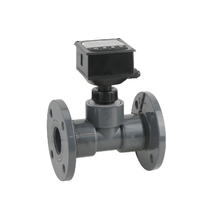
Paddle Wheel Flow Meter Installation Methods
Paddle wheel flow meters primarily measure flow by inserting a paddle wheel probe into the fluid. Key considerations include the upstream and downstream straight pipe sections, insertion depth, installation method, and fittings.
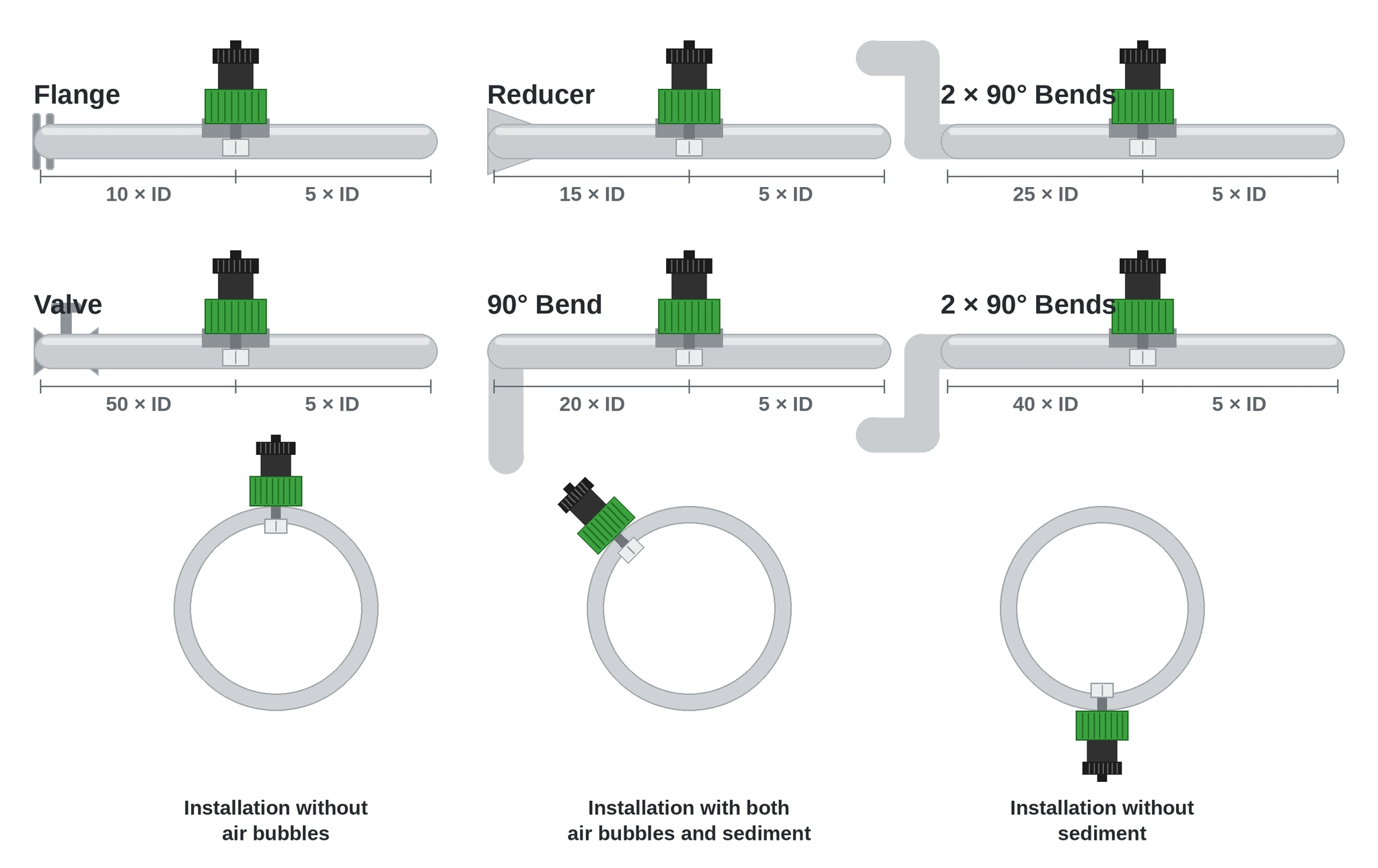
First, regarding straight pipe sections: since paddle wheel flow meters measure local flow near the pipe wall, the flow field must be stable to ensure accurate measurement. Generally, a straight pipe section of 10 times the pipe diameter is required upstream and 5 times the pipe diameter downstream.
If there are valves, pumps, elbows, or reducers upstream, the upstream section must be appropriately extended. Additionally, the installation should avoid the highest point of the pipeline and areas prone to air accumulation. It is best to select a location where the pipe is consistently full, such as the upward flow section of a vertical pipe or the middle to lower section of a horizontal pipe, to ensure the impeller remains fully submerged in the liquid. There must be no air pockets inside the pipe, as this will cause measurement errors.
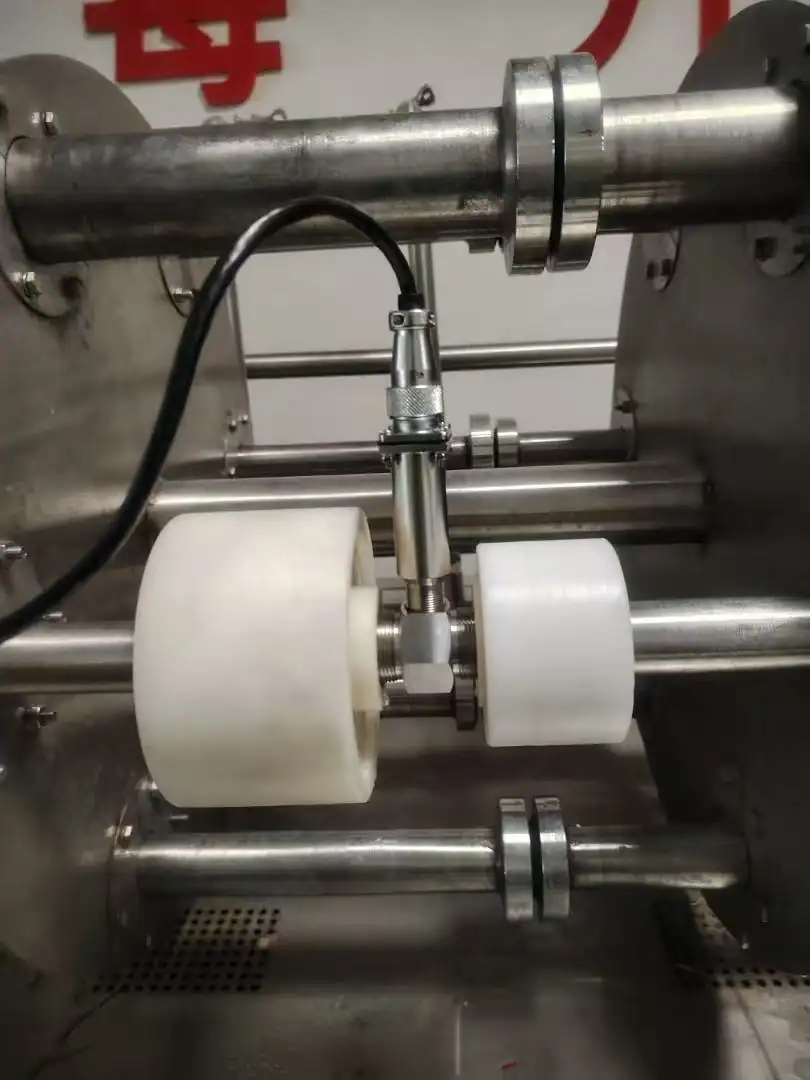
Insertion depth is the most critical step in installing an insertion-type paddle wheel flow meter. The impeller must be inserted to the position specified in the manual so that it is located at a representative velocity point. The depth corresponds to the specific pipe inner diameter, and the insertion depth varies by pipe size. Therefore, be sure to confirm the actual pipe inner diameter before installation and position the meter according to the reference values we provide.
The primary installation method involves drilling a hole and installing a mounting base. After drilling a hole in the pipe wall, weld or use a saddle clamp to secure a threaded mounting base (commonly 1-inch or 2-inch), then screw the sensor into place and seal it. Special installation accessories, such as flange clamps, are also available.
After a period of use, electromagnetic flow meters may experience a decrease in accuracy. Magnetic flow meter calibration eliminates systematic errors inherent in the instrument, ensuring the reliability of its measurement results. This meets the needs of process control, cost accounting, and trade settlement. Electromagnetic flow meters are suitable for measuring the flow rate of … Read more
Nitrogen Flow Controllers are devices specifically designed for measuring and controlling nitrogen flow. They not only measure the volumetric or mass flow rate of nitrogen, but crucially, they also control the flow rate. Generally, they are based on a nitrogen flow meter, with the addition of an automatic control valve and a closed-loop control system. … Read more
Measuring flow in large pipes with insertion type flow meters. If you need to measure the fluid flow of a larger pipe diameter, you are most likely to choose an insertion type flow meter. But what insertion type flow meter should you use? The market has insertion electromagnetic flowmeter, insertion vortex flowmeter, insertion ultrasonic flowmeter, … Read more
Thermal Mass Flow Meters and thermal mass flow controllers are suitable for most gaseous media. If a gas mass flow controller or thermal mass flow meter is factory-calibrated for one gas, but you want to switch to another, then a gas correction factor (GCF) is needed. What is Thermal Mass Flow Meter Correction Factor? The … Read more
Analog gas flow meters specifically refer to a type of flow meter that outputs analog signals. The main function of a flow meter is to measure volumetric flow rate or mass flow rate and convert it into an electrical signal output, facilitating flow monitoring and control. There are four types of flow meter signal outputs: … Read more
What is the turbine flow meter K factor? This question has garnered considerable attention. The K factor of a turbine flow meter is a coefficient that represents the ratio of the number of pulses in a high-frequency pulse signal to the volumetric flow rate. The turbine flow meter K factor is fundamental data used in … Read more
Sino-Inst’s Paddle Wheel Flow Meters cover pipe diameters from DN15 to DN600, offering stability, reliability, corrosion resistance, durability, and a long service life. Customization with special parameters such as PVDF, SS316L, and brass is also supported. Please feel free to contact our sales engineers.