
How to Adjust a Pressure Switch
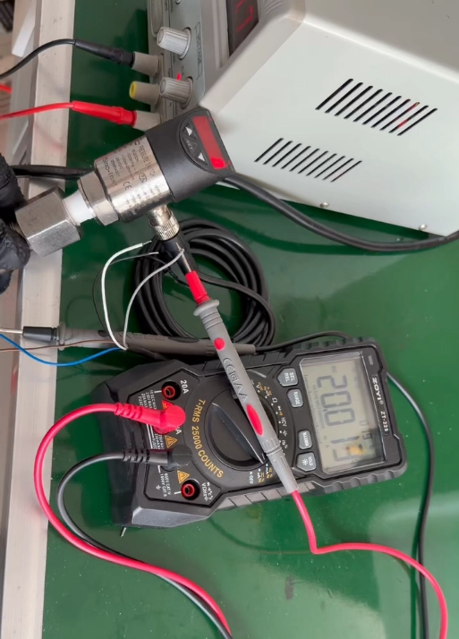
How to Adjust a Pressure Switch? This is a common question among the vast majority of pressure switch users. Whether it’s a mechanical or electronic pressure switch, there are three adjustable parameters: the set point (cut-out), the reset point (cut-in), and the hysteresis—the difference between the two.
Mechanical pressure switches have a simple structure and are generally adjusted using a nut. Electronic pressure switches are smarter and more convenient, allowing direct settings via buttons.
Next, let’s take a detailed look at how to adjust a pressure switch.
Set Point, Reset Point, and Differential
Adjusting a pressure switch refers to adjusting three parameters: the set point (cut-out), the reset point (cut-in), and the differential.
The set point (cut-out) of a pressure switch is the pressure value at which the switch must actuate. When the system pressure reaches the preset value, the switch contacts change state. The pressure switch can be configured to operate on rising pressure (high-level alarm) or falling pressure (low-level alarm). For example, in water supply systems, it is commonly set to approximately 1.5–3 Bar, while in air compressors, it is typically set to approximately 7–10 Bar.
The reset point (reset point / cut-in) of a pressure switch refers to the point at which the contacts return to their normal state when the pressure returns to the set point. The pressure switch then resets to its normal operating condition.
Hysteresis is the difference between the rising and falling pressure values during the operation of a pressure switch. It is typically approximately 1% to 3% of the switching range. For pressure switches with adjustable hysteresis, this value can be adjusted between approximately 5% and 12% of the switching range.
For example: A 40/60 psi switch used for a well pump closes when the pressure drops to 40 psi, causing the pump to start. It opens when the pressure rises to 60 psi, causing the pump to stop. The hysteresis is 20 psi. When used for low-pressure protection, the direction of operation is exactly the opposite; therefore, the “cut-in” point cannot simply be understood as “the lower point.”
Preparations Before Adjustment
Thorough preparation before beginning the adjustment process can prevent most operational errors.
First, confirm the model and specifications of the pressure switch. Understand its operating pressure range and setpoint range. These parameters can generally be found on the product nameplate or in the instruction manual.
Next, gather the necessary tools. Adjusting a mechanical pressure switch requires a screwdriver; you may also want to prepare testing equipment such as wrenches and a pressure gauge to monitor the actual system pressure.
A hand-operated pressure pump or pressure calibration bench, and a standard pressure gauge.
Before adjustment, be sure to shut off the power or air supply to ensure the equipment is in a completely depressurized and safe state.
Then, carefully read the pressure switch’s user manual to understand the detailed adjustment procedures. Of course, you can also contact the supplier directly for guidance.
Mechanical and electronic pressure switches are two different products, and their adjustment steps vary. Let’s take a closer look below.
How to Adjust a Mechanical Pressure Switch?
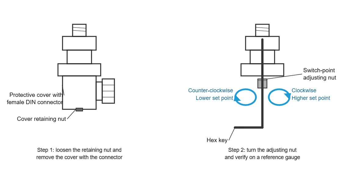
Typically, our mechanical pressure switches are shipped with pre-set switching points, and the hysteresis is also fixed. For example, our 2010 series products feature a single-nut adjustment mechanism. Users can adjust the switching points: either set the upper switching value (overpressure alarm, pump shutdown) or the lower switching value (low-pressure alarm, pump start), with the other point determined by the fixed hysteresis.
- First, mount the pressure switch on a calibration stand and connect it to a pressure source.
- Use a screwdriver to loosen the protective cover’s retaining nut, then remove the protective cover and the female connector. When removing the cover, do not rotate the HARTING connector side-to-side to avoid breaking the internal wiring.
- Connect a multimeter to the NO or NC contacts.
- Use a hand pump to increase the pressure to the target value, using the standard gauge reading as a reference.
- Use a screwdriver to adjust the pressure switch set points; turn clockwise to increase the value and counterclockwise to decrease it. Continue until the multimeter exactly switches on and off at this pressure.
- Vary the pressure back and forth around the target value to verify the activation point during pressure increase; then continue to reduce the pressure and record the reset point.
- Tighten the locking nut, reinstall the protective cover, and verify the settings once more.
How to Adjust an Electronic Pressure Switch?
Electronic pressure switches are more sophisticated and use a microprocessor to control digital or analog output signals. Taking our electronic pressure switch as an example, adjustments can be made using the buttons next to the display.
Each output channel of an electronic pressure switch is determined by two parameters: ALxH is the engagement value (the point at which the contacts close and the indicator light turns on), and ALxF is the release value (the point at which the contacts open and the indicator light turns off); x represents Channel 1 or Channel 2.
ALxH > ALxF: Upper limit operation. The switch engages when the pressure rises to ALxH and disengages when it drops below ALxF.
ALxH < ALxF: Lower limit operation. The switch engages when the pressure drops to ALxH and disengages when it rises above ALxF.
The difference between the two is the hysteresis, which can be set arbitrarily. Mechanical switches cannot achieve this.
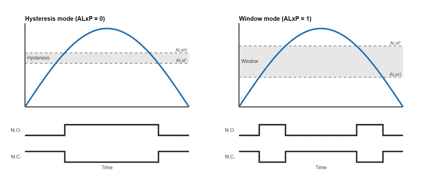
Hysteresis Mode (ALxP = 0): A single output point can handle “pump start at low pressure, pump stop at high pressure.” The output engages only when the pressure exceeds the engagement value and disengages only when it falls below the release value.
Window Mode (ALxP = 1): The output engages when the pressure is between the engagement and release values and disengages when it exceeds this range; this is suitable for monitoring “normal pressure” conditions or for out-of-limit alarms. There is also a hysteresis parameter ALxC (0–20%) for the window edges, used to prevent flickering at the edges.
The adjustment procedure is essentially the same as for mechanical pressure switches, except that nut adjustment is replaced by button adjustment. Button setup procedure:
In measurement mode, press the MODE button; the screen will display “LOCK.”
- Use the ▲▼ buttons to enter the user password 0001, then press MODE to confirm.
- Use the ▲▼ keys to select a menu item: AL1H, AL1F, AL1d, AL2H, AL2F, AL2d, or END.
- Press MODE to enter the selected item, use ▲▼ to adjust the value, then press MODE to confirm.
- After making all adjustments, select END and press MODE to save and exit.
Note: If no buttons are pressed for 30 seconds while in setup mode, the switch will automatically exit without saving the changes. Many users have reported that “the settings revert after being configured”—this is the reason why. Be sure to press the END button at the end to save your changes. For the “Transmitter Output Fine-Tuning” and “Restore Factory Settings” options in the Advanced Menu, we recommend that you have our technical staff perform these operations.
ALxd is the action delay, which can be set from 0 to 30 seconds. This indicates the time that must elapse after the pressure reaches the switching point before an output is generated. In situations where the pump outlet pressure pulsates or experiences water hammer, setting this to 1–3 seconds can significantly reduce false triggers.
Application Example: Confirmation Signal for Vacuum Chamber Leakage to Atmosphere
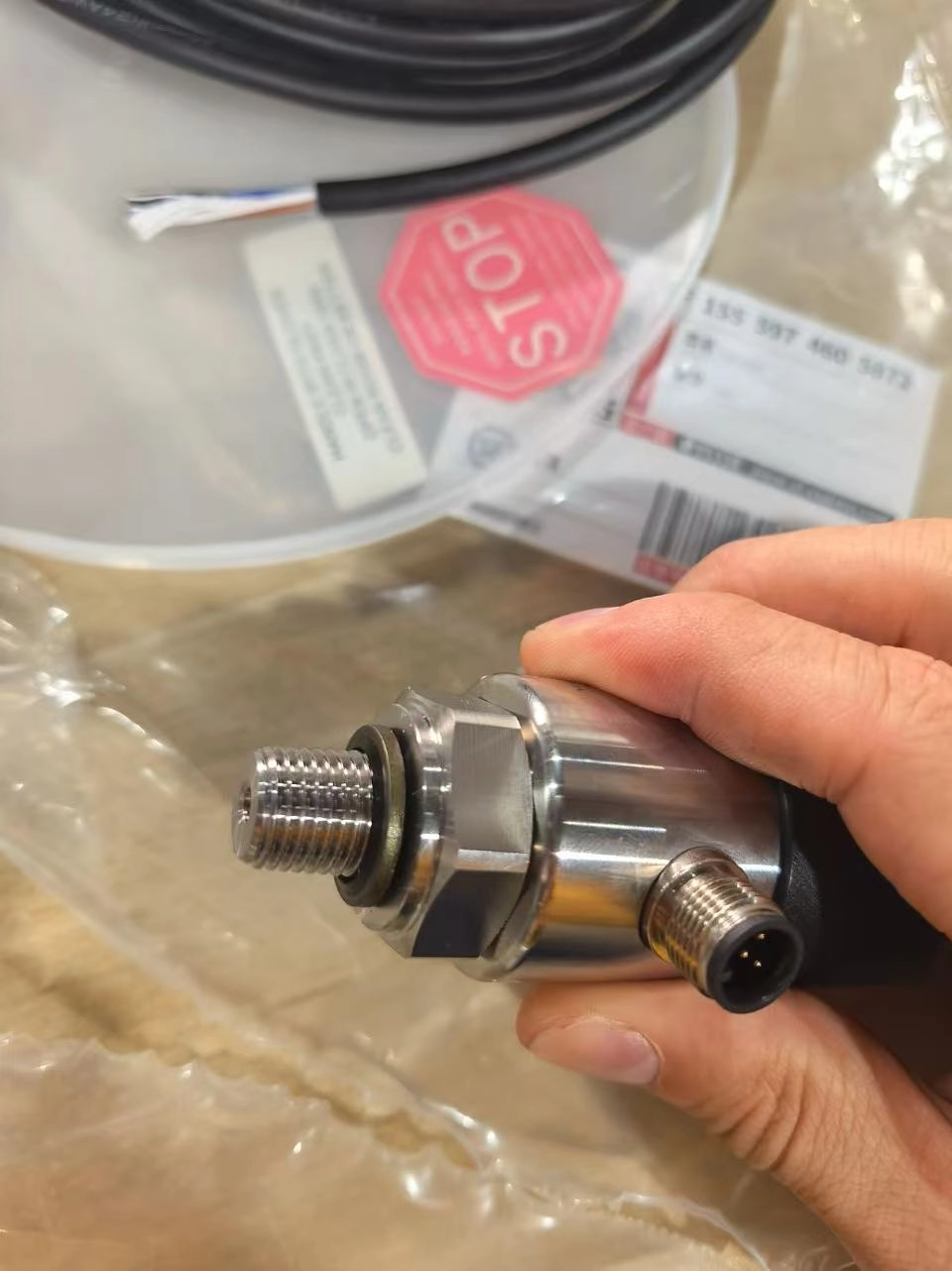
One of our customers operates a semiconductor/display panel equipment factory. The customer needed to install a pressure switch on each vacuum chamber of their equipment. During operation, the vacuum level in the chambers reaches a maximum of approximately 1.5×10⁻⁴ Pa; when the chamber needs to be vented to atmospheric pressure, the switch must send a “Reached Atmospheric Pressure” safety confirmation signal to the PLC the moment the pressure returns to atmospheric pressure. Only after the PLC receives this signal is the chamber door permitted to open.
The customer initially intended to use a mechanical switch without a display. After technical verification, we found that the mechanical switch has a measurement range of 0–120 kPa gauge pressure, with a minimum settable value of 20 kPa gauge pressure. However, “return to atmospheric pressure” corresponds to 0 kPa gauge pressure, which is lower than the minimum settable value; the mechanical switch simply cannot be set to this point. Additionally, the pressure-sensing element of a gauge pressure switch is incapable of measuring on the vacuum side (negative gauge pressure).
We recommend replacing it with an electronic pressure switch with a display, with a range of −100 to 0 kPa (gauge pressure), where the 4–20 mA output corresponds to 4 mA at −100 kPa and 20 mA at 0 kPa. The trade-off is that it requires a 24 VDC power supply, and the wiring configuration differs from that of the mechanical switch.
Several questions raised by the customer during commissioning happen to be the areas where electronic switches are most prone to errors:
Gauge pressure or absolute pressure? The customer asked whether the display should show 0 or 101 kPa at atmospheric pressure. Our switch is a gauge pressure type; it displays 0 when the chamber is in equilibrium with the external atmosphere. The advantage of using a gauge pressure switch is that regardless of how atmospheric pressure fluctuates due to weather or altitude, the reading will always be 0 when “the chamber equals the external environment.”
What are the factory settings? The factory settings are: actuates when pressure is ≥ 0, and releases when pressure is < 0.
Normally open or normally closed? The customer adjusted the contact status based on the on-site logic and ultimately required a closed output when pressure is ≥ 0.
How should the delay be understood? The customer asked: “Why does the indicator light take a few seconds to turn on after the pressure has reached AL1H?” This is the AL1d activation delay: the output is not triggered until the pressure has been maintained for the set number of seconds after reaching the threshold. When used in safety interlocks, this delay prevents false triggering caused by pressure fluctuations during the pressurization process.
What should be noted when connecting to a PLC? When connecting PNP/NPN transistor outputs to a PLC, the PLC and the pressure switch must share the same power supply (common ground); otherwise, the PLC will not be able to read the signal.
FAQ
Recommended Pressure Switches
If you are replacing a switch rather than re-setting one, these three cover most of the cases in this article: a single-nut mechanical switch with fixed hysteresis, and two digital switches whose set and reset points are entered from the keypad.
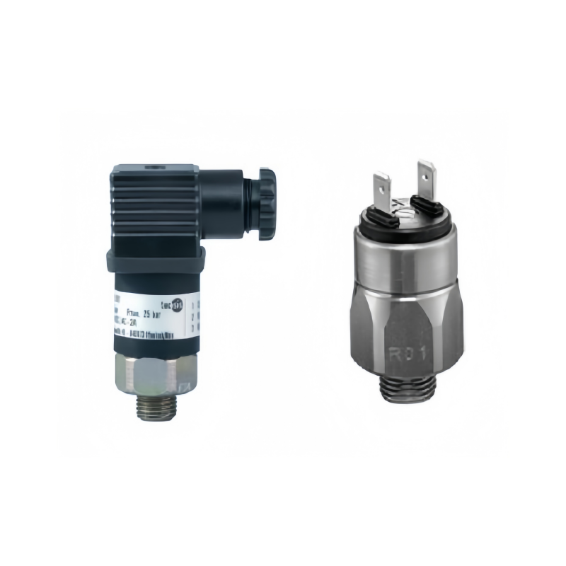
Mechanical Adjustable Pressure Switch
Single-nut setpoint adjustment, fixed hysteresis 10–20% of set value. Diaphragm type 0.2–12 bar, piston type 10–400 bar, IP65.
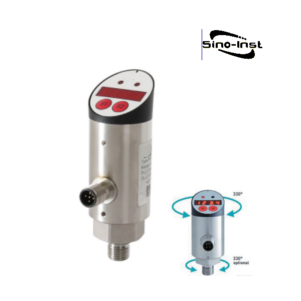
Electronic Pressure Switch with LED Display
0–600 bar, ±0.5% FS, upper and lower setpoints set from the buttons, adjustable hysteresis, 4–20 mA optional.
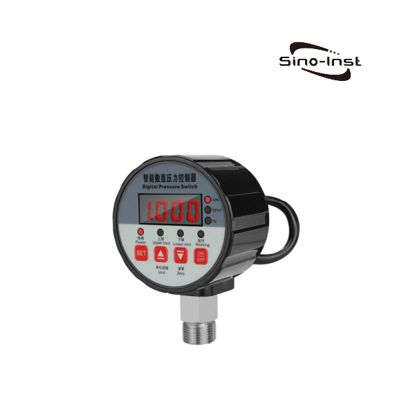
2080 Digital Pressure Switch
Relay output with settable hysteresis and 1–99 s delay. The 20804K variant is pre-configured for air compressor start/stop.
Related Reading

What Is a Pressure Switch?
Working principle, symbols, output types and selection — the background for the settings in this article.
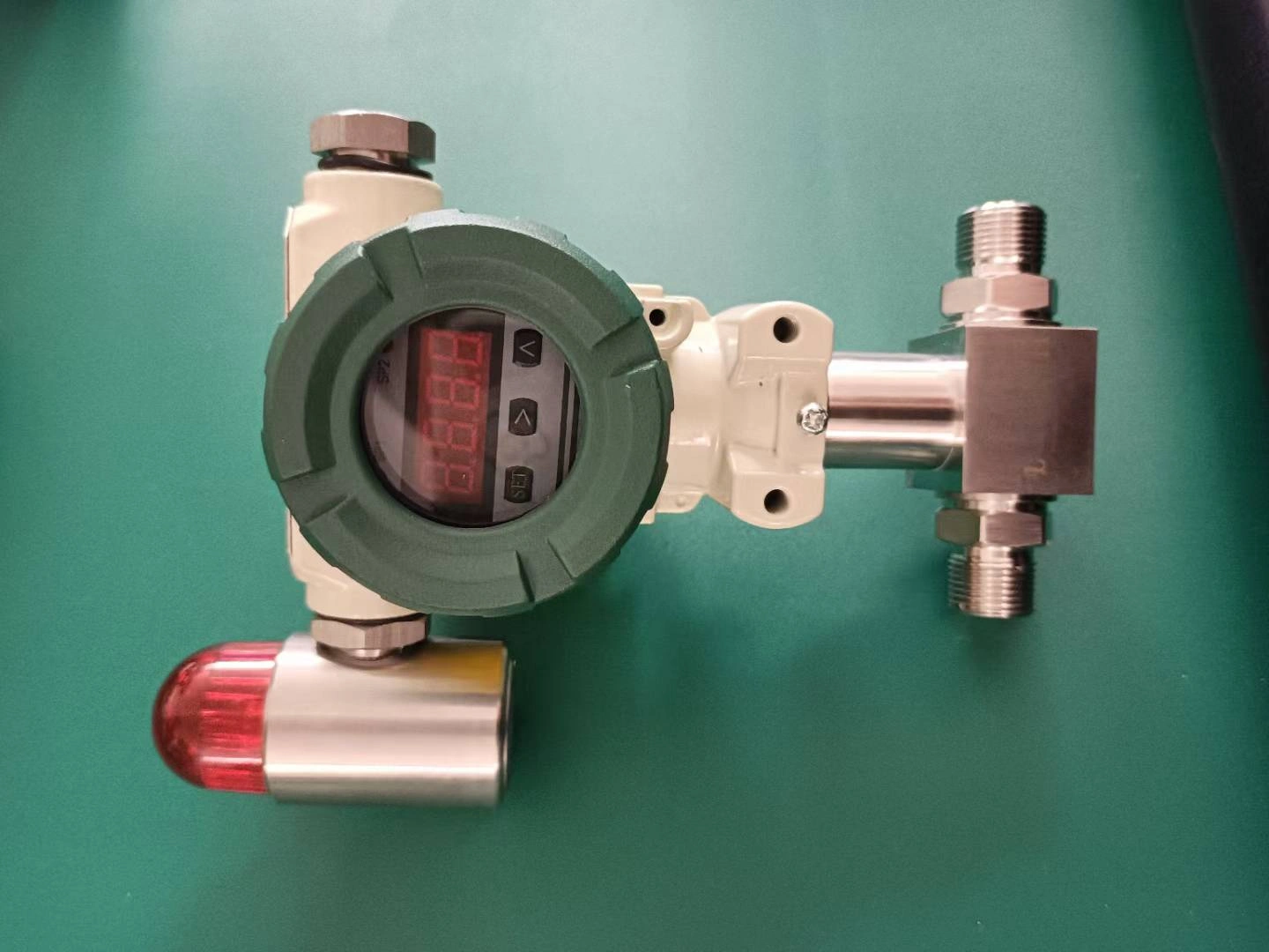
How Does a Differential Pressure Switch Work?
Setpoint and hysteresis selection for differential pressure switches, including filter and flow-interlock alarms.

Pressure Switch vs Sensor
When a switch is enough and when you need a transmitter instead, with the wiring and signal differences.
Need Help Setting a Pressure Switch?
Tell us the model on your nameplate, the pressure range you need and the medium. Our engineers will confirm the setpoint and hysteresis for your application and quote a replacement if the old switch is past saving.

Zhang Wei, possesses 20 years of experience as an automation instrumentation engineer, specializing in the research, design, installation, commissioning, and maintenance of automation instruments.
Face to various instrument communication protocols (such as Modbus, Profibus, etc.), with solid hardware circuit design and software programming skills (proficient in C language and PLC programming). Has extensive project experience; projects he has led and participated in have all achieved outstanding results, improving product accuracy, reducing costs, and increasing production efficiency.
Possesses excellent communication and coordination skills and a strong team spirit, enabling him to quickly respond to customer needs and provide high-quality automation instrumentation solutions.
Want to see more of our engineering guides in Google Search? Add Sino-Inst as a preferred source.