
Radar Level Control for Sump Pits: 80GHz Solution
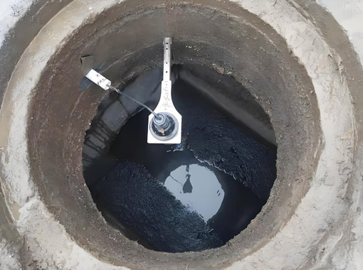
In projects involving liquid level control in 12-foot-deep collection pits, float-type level switches are a common traditional solution. However, these contact-type devices are prone to becoming entangled with debris, silted up, or jammed in sewage applications, leading to frequent malfunctions.
Based on our field experience, we highly recommend the 80 GHz radar level transmitter, which uses non-contact measurement to completely eliminate risks such as submersion and entanglement.
Challenges in Sump Applications
Sump pits act as core drainage and flood-prevention facilities for underground buildings. Their working conditions are harsh: the space stays damp and enclosed, sediment builds up constantly, and equipment faces long-term water immersion. The precision and stability of level measurement in these pits directly influence how well the drainage system runs, and are vital for the safety of underground spaces.
1. Frequent clogging and mechanical jamming: Sediment, fallen leaves and fibrous waste keep accumulating inside sumps. Conventional float switches and standard measuring probes easily get tangled or coated with dirt. This breaks level monitoring functions and causes irregular pump on-off actions.
2. Tricky adjustments and heavy maintenance burden: Sump pits stay water-filled and sit within closed, humid spaces. The trigger points of float switches depend on mechanical positioning hardware. To adjust the high and low liquid level trigger values, it is often necessary for personnel to go down into the well to perform the adjustments.
3. No continuous level monitoring capability: Float switches only deliver discrete on-off signals. They cannot feed back real-time water-height data. Slow water-level rise and drop cannot be captured, which makes early-warning setup and level-trend data recording hard to realize.
4. Limited potential for smart system integration: Float switches can directly turn water pumps on and off, yet they only output simple status signals. It is difficult to connect them seamlessly to PLC control cabinets or building automation platforms. Operators have to carry out regular on-site checks manually.
To address these pain points and drawing on practical engineering experience, this article provides a comprehensive comparison of 80 GHz radar and float-based level measurement methods for sump pits. It also presents proprietary solutions from the original manufacturer that precisely meet the needs of various engineering applications.
Primary/secondary Redundancy Configuration
The solution does not recommend “completely replacing float switches with radar”; a more practical approach for engineering applications is to use radar as the primary control and a high-level float switch as a backup alarm:
80 GHz Radar (Primary Control): Responsible for continuous daily liquid level monitoring, outputting a 4–20 mA continuous signal to the PLC. It supports the configuration of multiple liquid level thresholds and liquid level trends, and allows for real-time adjustment of start/stop points via software, enabling automatic pump activation, rotation, and early warning. This addresses the limitations of float switches, which do not provide continuous liquid level monitoring and require entering the well to adjust set points.
High-Level Float Switch (Backup, Independent Circuit): Installed only at the highest warning water level before overflow, it does not participate in normal pump start/stop operations. If the radar fails, the antenna becomes fouled, or the signal is lost—causing the water level to continue rising—the float switch will independently trigger an alarm or force the backup pump to start, serving as the final line of defense against overflow.
The two signal sources cross-verify each other within the PLC: When the radar reading and the float switch status are inconsistent (e.g., the radar indicates a low water level but the backup float switch has already activated), the system immediately identifies this as an instrument failure and triggers an alarm, preventing latent failures such as “normal readings despite actual overflow.”
From a product configuration perspective, this also provides a reasonable application role for the float switch—as a high-level backup alarm switch, rather than as the primary measuring element.
80 GHz Radar vs. Float-Type Level Transmitter
| Comparison Criteria | 80 GHz Radar Level Transmitter | Float-Type Level Transmitter |
| Measurement Principle | High-frequency electromagnetic waves (FMCW), non-contact | Float rises and falls with the liquid level, mechanical/magnetic coupling |
| Measurement Accuracy | ±1 mm to ±2 mm | ±10 mm to ±50 mm (±5 cm) |
| Blind Zone | 50 mm–80 mm | 300 mm or more, or limited by the float’s travel range |
| Beam Angle | 2°–6°, concentrated energy | Not applicable (mechanical structure) |
| Interference Resistance | Penetrates foam, dust, and steam; resistant to agitation | Prone to jamming due to medium viscosity, impurities, and suspended solids |
| Maintenance Costs | Extremely low. No mechanical parts; maintenance-free | Relatively high. Float is prone to jamming, wear, and corrosion |
| Remote Monitoring | Supports 4–20 mA, HART, and RS485; easy to integrate with DCS/PLC | Partially supports remote transmission, but signal stability is poor |
Recommended Products for Sump Pit Level Measurement
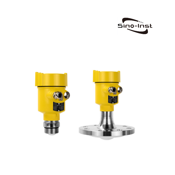
80GHz Radar Level Transmitter
FMW series FMCW radar, 76-81 GHz. Accuracy down to ±1 mm with a 3° beam angle and 0.08-0.1 m blind zone. Non-contact choice for sewage sumps and collection wells.
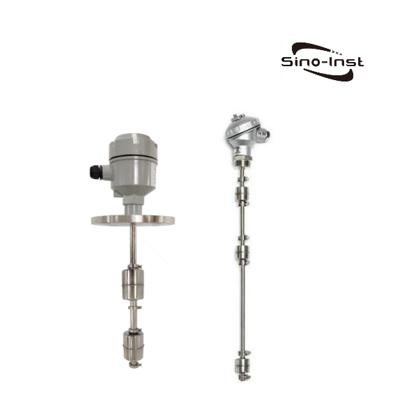
Multi Level Float Switch/Controller
Float switch with 1-4 switching points on one cable. Simple independent circuit that fits the high-level backup alarm role described in this article.
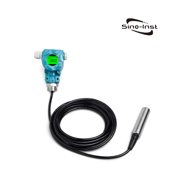
Submersible Level Transmitter
Hydrostatic sensor lowered into the pit, with multiple range options and 4-20 mA output. A contact-type alternative for clean water sumps and deep wells.
Operating Characteristics of 80 GHz Radar in Sump Applications
- Non-contact measurement: The sensor is mounted on top of the sump. The radar beam is emitted downward, and the liquid level is calculated based on the echo. The probe is not submerged in wastewater and does not come into contact with sludge, hair, or fibrous debris.
- Narrow-beam anti-interference performance: 80 GHz radar has a wavelength of roughly 3.75 mm. Its beam angle can shrink down to 3° or smaller to concentrate signal energy. The narrow beam aims precisely at the actual water surface.
- Small near-end blind zone: During heavy-rain events, water level rises fast and may get extremely close to the antenna. The blind zone of 80 GHz radar can stay below 0.1 m, and stable output remains even when the water surface sits right beneath the antenna.
- Tolerance against foam and multi-phase flow: 80 GHz radar signals show strong penetration performance; surface foam will not directly cause signal loss. Combined with FFT signal-processing algorithms, true liquid-surface echoes can still be distinguished under low signal-to-noise-ratio conditions.
- Good measuring-range adaptability: For sump pits deeper than ten feet, 80 GHz radar fits well. Extended guide rods or pull cables are not required, so common faults like guide-rod deformation and cable tangling no longer exist.
- Continuous liquid-level signal output: The transmitter outputs real-time 4–20 mA or digital signals with continuous level values. This supports over-threshold early warning, historical data logging, and easy connection to PLC and higher-level monitoring platforms.
Typical Performance Specifications
| Parameter | Typical Value |
| Measuring Range | 0.1–65 m; up to 80 m for some models |
| Accuracy | ≤±3 mm |
| Beam Angle | 3°–5° |
| Protection Rating | IP68 (can be briefly submerged) |
| Output Interface | RS-485 Modbus RTU; supports Bluetooth remote debugging |
Case: 12-Foot Sump
The depth of the pit at the site is assumed to be 12 ft, or approximately 3.66 m. The radar is mounted at the top of the pit and transmits downward; the beam is conical and widens as it descends. The diameter of the spot at the bottom of the pit is calculated using the following formula:
D = 2 × H × tan(θ/2)
Here, H is the distance from the antenna to the bottom of the pit (taken as 3.66 m), and θ is the beam angle. Calculations were performed based on three common lens specifications:
| Beam Angle θ | tan(θ/2) | Spot Diameter at the Bottom of the Pit D |
| 3° | 0.0262 | approx. 0.19 m |
| 6° | 0.0524 | approx. 0.38 m |
| 8° | 0.0699 | approx. 0.51 m |
Comparison of Operating Principles
The 80 GHz radar level transmitter utilizes the FMCW principle and is a non-contact measurement device.
Electromagnetic waves penetrate the air and surface foam in the sump to reach the wastewater surface. A portion of the signal is reflected back to the antenna, forming an echo. The instrument compares the frequency difference Δf between the transmitted signal and the echo, and calculates the distance from the liquid surface to the antenna based on the direct proportional relationship between the frequency difference and the propagation distance.
Distance calculation formula: R = (c × Δf) / (2 × S)
- R — Distance from the antenna to the liquid surface
- c — Speed of electromagnetic waves in air
- Δf — Frequency difference between the transmitted signal and the echo signal
- S — Frequency modulation slope
When installed in a sump filled with wastewater, no components are submerged in the wastewater during the measurement process. The narrow beam also minimizes false echo interference caused by submersible pumps, pipes, and brackets inside the sump.
Float-type level gauges are based on Archimedes’ principle of buoyancy and utilize mechanical or magnetic coupling mechanisms to detect level positions.
F = ρ × g × V (buoyancy force = liquid density × gravitational acceleration × displaced volume)
In sewage sump applications, the float and connecting rod are fully submerged in the wastewater, and impurities in the water can easily become entangled around the float and guide rod. Sludge accumulation at the bottom of the sump can also support the float, preventing it from moving freely with the water level.
Its measurement relies entirely on the entire set of moving mechanical components. Once debris becomes lodged or components corrode or wear out, signal failure may occur, triggering abnormal pump interlocks.
Precautions
- Selection of installation location. Avoid installing directly above the inlet or outlet whenever possible.
- Antenna protection. For sewage sumps, prioritize antennas made of hydrophobic materials such as PTFE or FEP.
- Allow for maintenance access. Ensure sufficient working space around the installation location on top of the sump to facilitate future Bluetooth debugging and antenna cleaning.
- Range and dead zone settings. Strictly set the empty tank and full tank levels based on the actual pit depth at the site; do not operate beyond the measurement range.
- Bluetooth supports only short-range on-site debugging. Long-term data acquisition and interlock control rely on 4–20 mA or RS485 Modbus RTU signals.
- Perform regular inspections and cleaning. Oil and sludge in wastewater can accumulate over time and adhere to the antenna surface.
- Check signal status. During routine inspections, in addition to verifying level readings, check the quality of the instrument’s echo.
- Avoid unauthorized parameter changes. After commissioning is complete, lock the instrument parameters and prohibit on-site personnel from making arbitrary modifications.
Further Reading
- 80GHz Radar Level Sensors: Siemens LR110/LR120 Alternative
- Single & Multi Liquid Level Float Switches – Effective Level Control
- Case Study: Four-Point Liquid Level Control Using a Float Level Switch
FAQ
As a leading manufacturer of level measurement solutions for collection wells, Sino-inst offers one-stop, turnkey solutions centered around 80 GHz radar level sensors and can customize solutions tailored to specific project conditions.

Zhang Wei, possesses 20 years of experience as an automation instrumentation engineer, specializing in the research, design, installation, commissioning, and maintenance of automation instruments.
Face to various instrument communication protocols (such as Modbus, Profibus, etc.), with solid hardware circuit design and software programming skills (proficient in C language and PLC programming). Has extensive project experience; projects he has led and participated in have all achieved outstanding results, improving product accuracy, reducing costs, and increasing production efficiency.
Possesses excellent communication and coordination skills and a strong team spirit, enabling him to quickly respond to customer needs and provide high-quality automation instrumentation solutions.
Want to see more of our engineering guides in Google Search? Add Sino-Inst as a preferred source.