
Gear Flow Meters for Viscous and Corrosive Low Flow Dosing
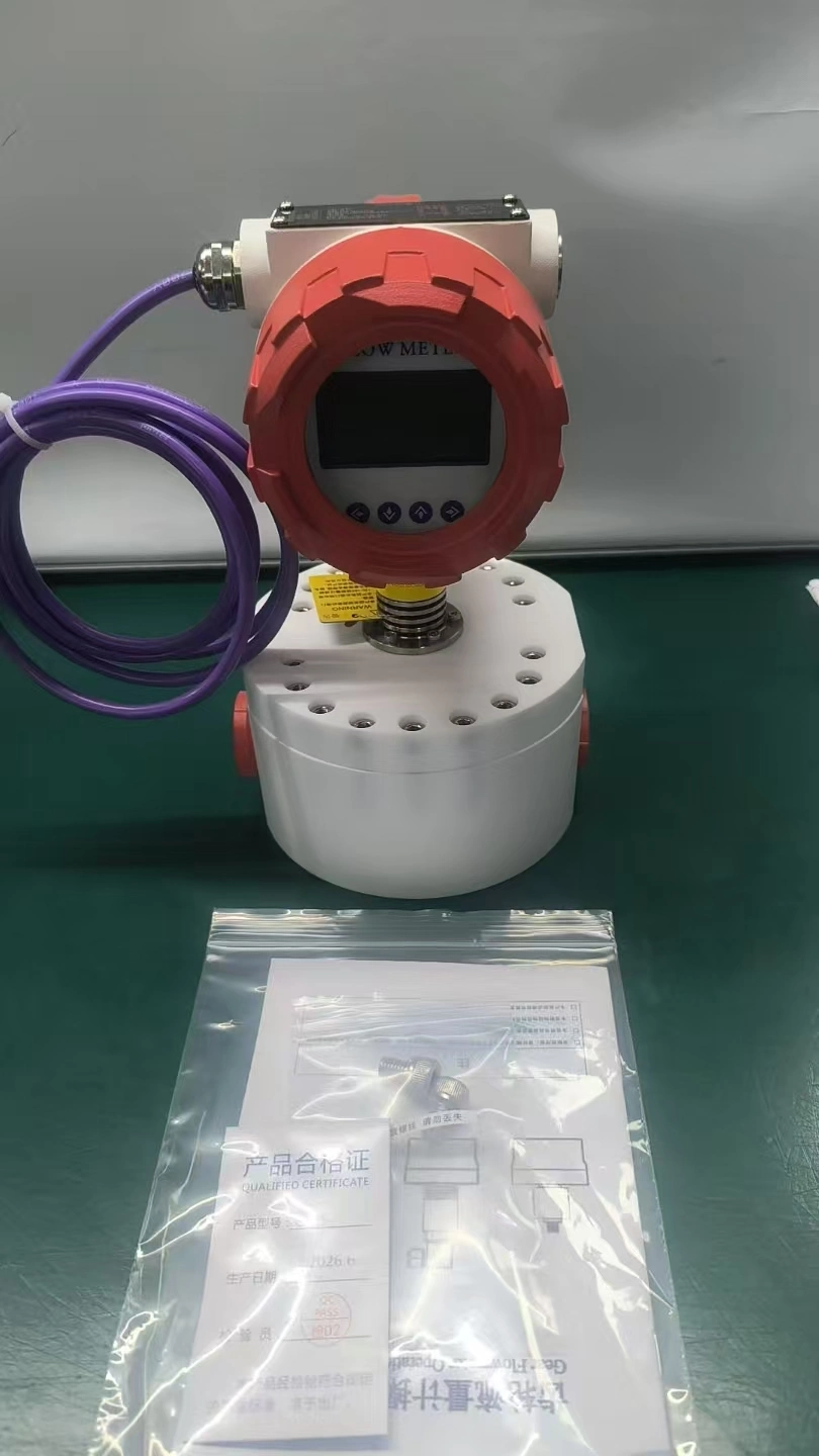
We have provided customized flow measurement solutions for various clients dealing with high-viscosity, low-flow, and corrosive operating conditions. For instance, a polyurethane production line in Nigeria required the metering of a resin with a viscosity of approximately 2000 cP at a flow rate of less than 5 gallons per hour (approx. 19 liters per hour), with a requirement for a 4–20 mA output signal. Another chemical manufacturer needed to meter sulfur monochloride at flow rates of up to 2 liters per minute, requiring an RS485 output signal. The former application presented challenges primarily related to viscosity—such as pressure drop and material buildup—while the latter focused on corrosion; sulfur monochloride hydrolyzes in the presence of moist air to form hydrogen chloride (HCl) and sulfur dioxide (SO₂), with the precipitation of elemental sulfur.
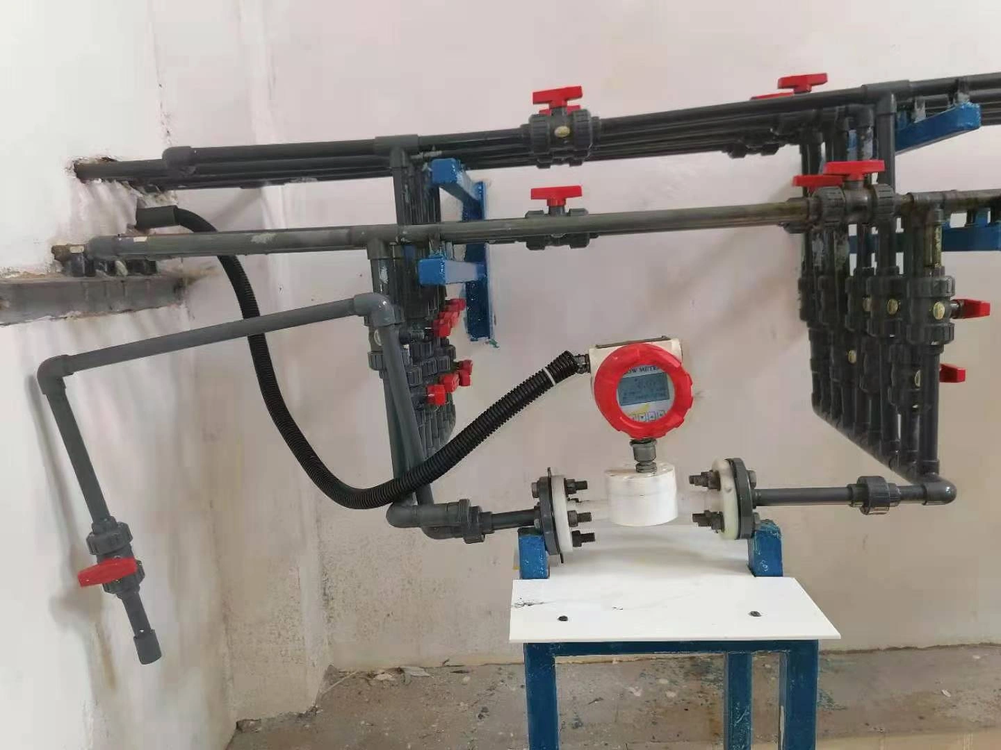
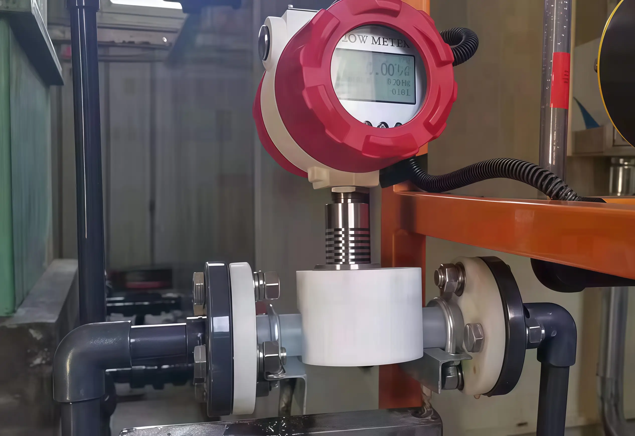
These are classic examples of metering scenarios involving high-viscosity, low-flow, and corrosive fluids. In such cases, our primary recommendation is a gear flow meter. For corrosive liquids, we use a gear flow meter built entirely from PTFE, with RS485 output. Its standard range is 0.6–50 L/h, so for larger corrosive flows like the 2 L/min sulfur monochloride duty, meter size and wetted material have to be decided together.
Measurement Challenges: High viscosity, low flow rates, and corrosiveness
High viscosity, low flow rates, and corrosiveness often present significant challenges in flow measurement; these three conditions do not act in isolation but rather couple with one another, compounding the difficulties.
“High viscosity” generally refers to operating conditions involving fluids with a viscosity exceeding 1,000 mPa·s (such as resins, asphalt, adhesives, and heavy oils). Such media possess inherently poor flow characteristics; as they pass through moving parts like gears and bearings, they generate substantial viscous shear resistance, leading to increased pressure loss across the meter.
High-viscosity media are also prone to accumulating on chamber walls and gear surfaces, altering the clearance between gear pairs and introducing measurement errors. Furthermore, high viscosity directly increases the rotational load on the gears, imposing stricter requirements on the meter’s starting torque.
Low flow is a different problem. A viscous liquid still turns the gears, because the pump pushes it through. With thin liquids such as water or solvents, part of the flow slips through the gear clearances without turning the gears. At low flow this slip becomes a large share of the total, so the meter reads low, and in extreme cases the gears stop while liquid still passes.
Thin liquids also leave little lubricating film on the gears and bearings, so they wear faster. Water, solvents and hot-water CIP are the hardest cases. As the gears wear, the clearances grow, slip increases and accuracy drifts.
Corrosive media can attack standard metal wetted parts—such as those made of 316L stainless steel—causing pitting and crevice corrosion, especially with chlorides and strong acids. Corrosion debris can jam the gear clearances, leading to meter malfunction. To withstand corrosion, it is often necessary to select non-metallic wetted materials, such as PTFE.
Why Choose a Gear Flow Meter?
Turbine and variable-area (rotameter) flow meters lose accuracy as viscosity rises and struggle at low flow rates. Electromagnetic flow meters need a conductive liquid, which rules out most oils, inks, solvents and resins.
As positive-displacement instruments, gear flowmeters are inherently well-suited for high-viscosity media, enabling high measurement accuracy even at low flow rates. However, when dealing with corrosive fluids, the material compatibility of wetted parts must also be considered.
Working principle
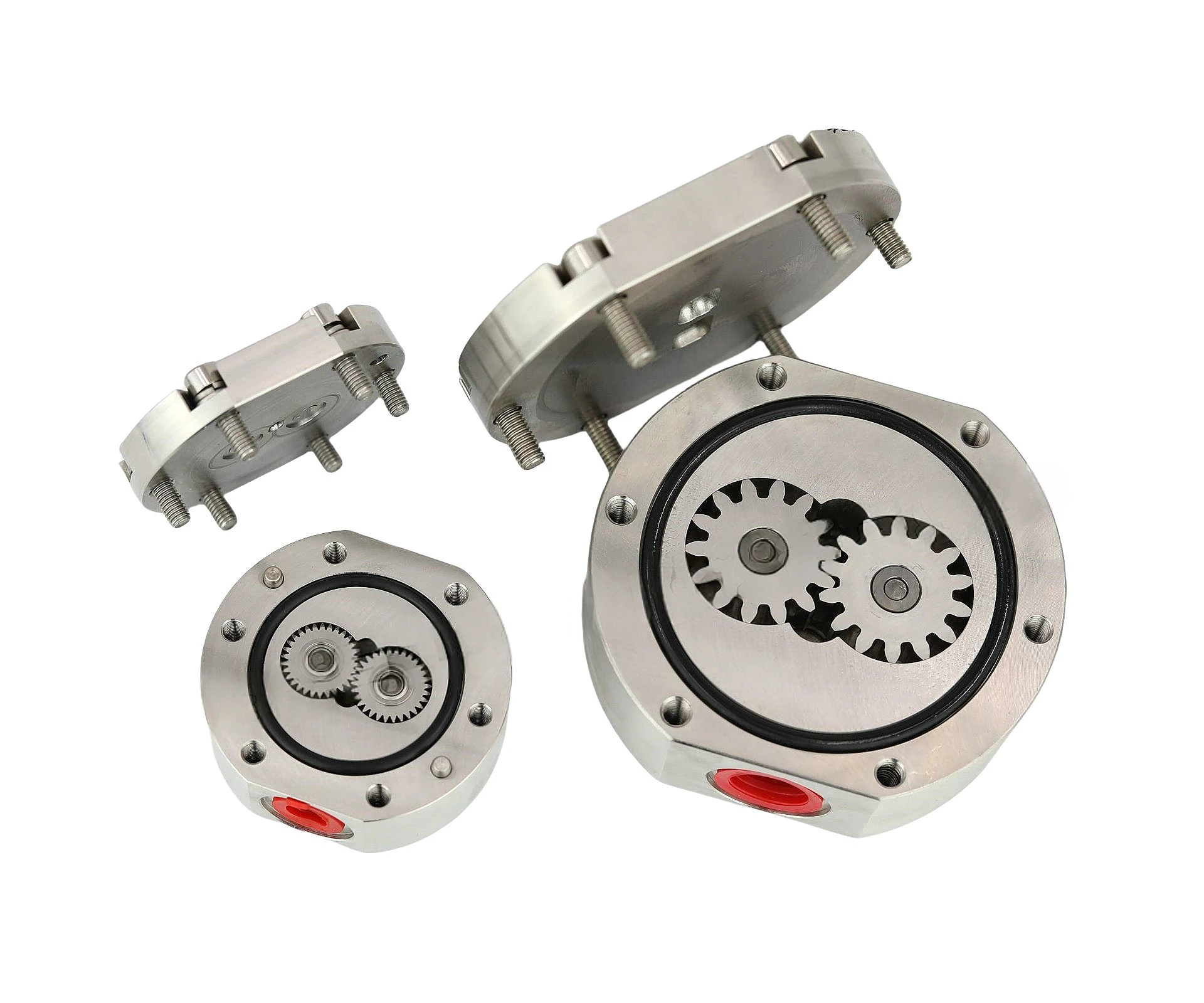
Gear flow meters operate on the positive-displacement measurement principle. The meter’s measuring chamber contains a pair of closely meshed gears (such as oval or cylindrical gears). As fluid enters the meter, the pressure difference between the upstream and downstream sides drives the gears to rotate.
“Closed measuring chambers” of fixed volume are formed between the gears and the housing. With each full rotation of the gears, a fixed volume of fluid is discharged. The flow rate can be calculated directly simply by recording the number of gear rotations or pulses.
Volume calculation formula: Q = N × V
Q: Total volume passed (flow rate = volume ÷ time)
N: Number of gear rotations
V: Fixed volume discharged per rotation
In practice, the meter outputs several pulses per rotation, and volume = pulse count ÷ K-factor (pulses per litre).
This mechanical structure—characterized by the principle of “displacing exactly what enters”—means the measurement mechanism relies entirely on physical space displacement rather than on the fluid’s velocity profile.
Key mechanism: The “reverse boost” effect of high-viscosity media
Conventional wisdom suggests that the more viscous a liquid is, the more difficult it is to measure. However, within a gear flow meter, high-viscosity media actually offer three major measurement advantages:
1. Significantly reduced internal clearance leakage
Micron-level mechanical clearances must be maintained between the gears and the housing, as well as between the gears themselves, to prevent seizing caused by friction during operation. With low-viscosity media (such as water or solvents), some liquid leaks through these tiny gaps from the high-pressure zone back to the low-pressure zone—a phenomenon known as clearance leakage—resulting in measurement errors.
High-viscosity liquids barely pass through these gaps, so leakage is small. It never reaches zero, and on thin liquids it rises fast, so calibrate the meter on the actual liquid. See how viscosity affects gear meters.
2. Lubrication, protection, and reduced mechanical wear
Oils, greases and hydraulic fluids leave a film on the gears and bearings, which cuts wear and extends meter life. Not every viscous liquid does this: filled adhesives and pigmented inks can be abrasive, and some adhesives cure inside the meter if it is not flushed.
3. Immunity to Reynolds number limitations
The meter factors of velocity-based flow meters (such as turbine or vortex flow meters) are highly dependent on the fluid’s Reynolds number. As viscosity rises, Reynolds number falls and the flow turns from turbulent to laminar. A turbine’s K-factor drifts, and a vortex meter stops giving a signal.
Gear flow meters, however, do not rely on the Reynolds number for measurement. Whether the flow is laminar or turbulent, as long as the fluid drives the gears to rotate, accurate measurement is achieved.
6 Core Advantages of Gear Flow Meters
Strong low-flow measuring capability
Through optimized gear modules, bearing design and measuring-chamber structure, micro-gear flow meters lower starting-flow threshold significantly. They pick up tiny flow variations that standard meters cannot capture.
Thanks to tightly controlled gear clearances, very small flow can drive gear movement. Our standard GF02 starts at 0.6 L/h (10 mL/min), and a custom stainless steel version goes down to 0.1 L/h (about 1.7 mL/min) on viscous liquids. Accuracy is ±0.5% of reading with 0.1% repeatability, suited to lubrication circuits and additive dosing.
Low sensitivity to fluid viscosity
Unlike velocity-type flow meters, gear flow meters are little affected by viscosity changes on oils and other viscous liquids. On water-like liquids, leakage rises, so calibrate on the actual liquid. High-viscosity fluid can lubricate gear assemblies, cut internal leakage and improve metering performance. They work for high-viscosity media including hydraulic oil, lubricants, resin, adhesive and honey.
Adaptable for corrosive process fluid
An all-PTFE version is available: every wetted part is PTFE, so the liquid never touches metal. It handles strong acids and alkalis (pH 0–14), organic solvents and alcohol mixtures. Limits: 0.6 MPa, −20 to 80 °C, 0.6–50 L/h, and the liquid must be free of particles.
High measurement accuracy and repeatability
General gear flow meters deliver ±0.5% of reading accuracy with 0.1% repeatability. This makes them suitable for strict-requirement applications within lab, pharmaceutical and fine-chemical industries.
Wide turndown ratio and flexible material options
Turndown reaches about 80:1 on viscous liquids (GF02: 0.6–50 L/h); larger sizes and thin liquids give less. Body options are aluminum alloy, stainless steel or all-PTFE, to suit different liquids.
Multiple mechanical readout and electrical output selections
Certain models adopt mechanical counters for local flow display without external power supply. Pulse, 4–20 mA and bus-based communication outputs are also offered for compatibility with both legacy and modern control systems.
Applications of Gear Flow Meters
Petrochemical Industry
Flow measurement for petroleum-based products such as heavy oil, asphalt and resin. Measurement of corrosive liquids including strong acid, strong alkali, salt solution and organic solvent (PTFE-wetted version).
Food and Pharmaceutical Industries
Dosing of edible oils, honey, syrups and pharmaceutical liquids. For milk and juice, a sanitary magnetic meter is usually the better choice.
Lubrication and Hydraulic Systems
Circulation flow monitoring, consumption tracking and leakage check for rotating-equipment lubrication circuits (steam turbine, compressor, machine-tool units). Pump performance test, hydraulic cylinder speed control and leakage monitoring; high-pressure variants can handle working pressure above 21MPa.
Chemical Processing
Measurement for coating, ink, resin, adhesive and organic-solvent process streams.
Gear Flow Meters for Viscous and Corrosive Liquids
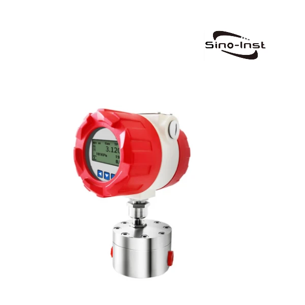
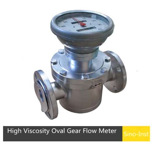
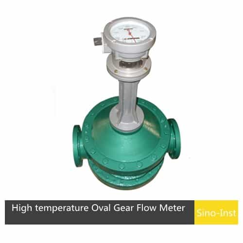
PTFE Wetted Parts Selection: Performance Advantages and Inherent Limitations
Polytetrafluoroethylene (PTFE), also widely known as “plastic king”, represents a high-performance polymer material. Its most notable feature lies in outstanding chemical inertness; it hardly dissolves in common solvents and resists attack from strong acid and alkali. It also performs well across wide high-low temperature range, normally working from −200 °C up to 260 °C.
PTFE delivers extremely low friction coefficient plus good non-stick and hydrophobic characteristics. These merits make it popular for sealing, corrosion-resistant and self-lubricating parts, yet its material properties also bring processing challenges.
Performance Advantages
1.Outstanding chemical inertness: PTFE features stable molecular structure. It stays inert toward most strong acids, strong alkalis, strong oxidizing agents, organic solvents and oil-based fluids. It fits seals, piping and containment components under harsh chemical operating conditions.
2.Broad temperature adaptability: PTFE keeps stable physical-chemical properties within −200 °C ~ +260 °C; short-time peak temperature can reach 300°C. It maintains shape and performance under both extreme high-temperature and cryogenic working points.
3.Ultra-low friction coefficient: PTFE has one of the lowest friction coefficients among known solid materials and shows good self-lubricating performance. It is well suited for oil-free bearing assemblies, sliding components and sealing rings.
4.Dense hydrophobic barrier property: PTFE carries very low surface energy, so few substances can stick firmly onto its surface. Its strong hydrophobic character repels water and most corrosive liquids, though small molecules such as HCl and chlorine can slowly permeate it.
5.Weather-aging resistance: UV radiation will not degrade PTFE. It resists aging and cracking under outdoor and complex ambient conditions. Meanwhile it is non-toxic, odor-free and has biocompatible properties.
Inherent Limitations
- Poor mechanical strength: PTFE tensile strength sits between 14–34 MPa, far below metallic materials. It easily deforms under sustained load (deformation 0.5%–3%), and long-term stress will reduce sealing pressure.
- Large thermal expansion coefficient: PTFE expands roughly 6–8 times as much as stainless steel. When assembled together with metal housing, it may suffer deformation, wrinkling or delamination and further lead to seal failure or medium leakage.
- Partial chemical incompatibility: PTFE cannot resist every kind of chemical. Molten alkali metal (sodium, potassium), elemental fluorine and certain strong fluorinating reagents will damage its molecular structure and degrade material performance.
- Boundary performance at extreme temperatures: Even though PTFE wide working range covers −200 °C ~ +260 °C, its mechanical strength drops and softening-deformation risk rises when approaching upper temperature limit. It keeps stable under low-temperature conditions but may turn brittle; dedicated structural design is needed for cryogenic-medium sealing
Key Considerations for PTFE Selection
While choosing PTFE as gear flow meter wetted material, the first step is checking medium chemical compatibility. PTFE suits hydrochloric acid, sulfur monochloride, strong alkalis and most solvents. Polyurethane and vinyl inks are not corrosive; a stainless steel meter handles them.
We need to evaluate the following aspects during material selection:
- Properties of the medium.
- Maximum operating temperature.
- Pressure and mechanical-load status.
- Medium cleanliness level.
- Special application-related requirements.
Two frequently ignored shortcomings should also be noted: First, low elastic modulus causes cold-flow deformation risk and potential seal failure. Second, large thermal expansion coefficient brings unstable dimensional change with temperature fluctuation.
Hence mechanical design must reserve proper compression allowance, and metal-reinforced structures are recommended to constrain material cold-flow deformation.
Sizing for Dosing: Pulse Resolution, Not Flow Range
For continuous flow, size the meter by flow range. For dosing (filling shots, batches, intermittent lubrication), what matters is how many pulses one dose produces.
- Pulse resolution. A GF02 gives about 0.095 mL per pulse: roughly 42 pulses for a 4 mL shot and 52 for a 5 cc grease shot. ±1 pulse must fall inside your dose tolerance.
- Response time. Very short shots are hard to measure in-line. One customer dosing 1 mL glue shots, 15 per minute, switched to a non-contact sensor on the tube.
- Batch control. For fixed batches, add a batch controller and a fast valve, and set an overrun correction. A molasses line dosing 2–6 kg batches at 60 °C needs exactly this.
- Pulsating pumps. Diaphragm pumps and air-driven grease pumps deliver flow in pulses. Read the dose from the totalizer, not the flow rate.
- Grease. Data sheets often list the base-oil viscosity; the grease itself is much stiffer. Send us the NLGI grade and pump pressure.
For hot, thick liquids, see Right Flow Meter for Molasses and High Viscosity Flow Meters.
Five Key Criteria for Selecting Gear Flow Meters
- Flow Range and Port Size Matching
Gear flow meters show better low-flow performance compared with oval gear meters. Our GF series runs from G1/8 to G1-1/2 (GF02–GF32), covering 0.6 L/h to 20 m³/h. Size by flow, not pipe size: keep normal flow mid-range and continuous flow below about 80% of maximum. Fit a strainer upstream, as particles are the main cause of gear meter failure. For large-flow scenarios, oval gear or twin-rotor meters represent more appropriate options. - Medium Viscosity Compatibility
Gear flow meters support broad viscosity spectrum, ranging from low-viscosity solvent to high-viscosity melt over 10000mPa·s. Higher viscosity improves internal sealing and measurement accuracy, but raises pressure drop and lowers the maximum flow of a given size. Give us the viscosity at the lowest operating temperature. - Temperature and Pressure Ranges
Standard GF meters run from −15 to 80 °C; special builds cover −196 to 200 °C, and the all-PTFE version −20 to 80 °C. Pressure ratings: aluminum body 1.6 MPa, stainless steel up to 40 MPa, all-PTFE 0.6 MPa. Check both medium and ambient temperature, and leave a pressure margin. - Accuracy Class Selection
Standard gear flow meters achieve accuracy class 0.5 (±0.5% of reading) with 0.1% repeatability. This usually satisfies general process monitoring and material-balance accounting needs. - Installation and Output Options
Gear flow meters are available in threaded or flanged connection forms. Threaded connections are widely adopted for small-size sensors for simple installation and compact layout. Output options include pulse signal, RS-485 bus and analog output. For hazardous-area installation, pick meters with qualified explosion-proof rating.
FAQ
For flow measurement tasks with high-viscosity, low-flow and corrosive media, gear flow meters deliver well-adapted solutions thanks to high accuracy, wide viscosity tolerance and good response to small-magnitude flow.
PTFE-constructed wetted parts deliver reliable corrosion resistance. Still users must take its inherent material limitations into account, mainly limited wear resistance and large thermal expansion coefficient.
Sino-Inst supplies PTFE-version gear flow meters covering many kinds of corrosive-medium conditions. We are ready to provide matching solutions for your site conditions. Feel free to get in touch with our team to resolve your flow-measurement challenges.
Further Reading
Zhang Wei, possesses 20 years of experience as an automation instrumentation engineer, specializing in the research, design, installation, commissioning, and maintenance of automation instruments.
Face to various instrument communication protocols (such as Modbus, Profibus, etc.), with solid hardware circuit design and software programming skills (proficient in C language and PLC programming). Has extensive project experience; projects he has led and participated in have all achieved outstanding results, improving product accuracy, reducing costs, and increasing production efficiency.
Possesses excellent communication and coordination skills and a strong team spirit, enabling him to quickly respond to customer needs and provide high-quality automation instrumentation solutions.