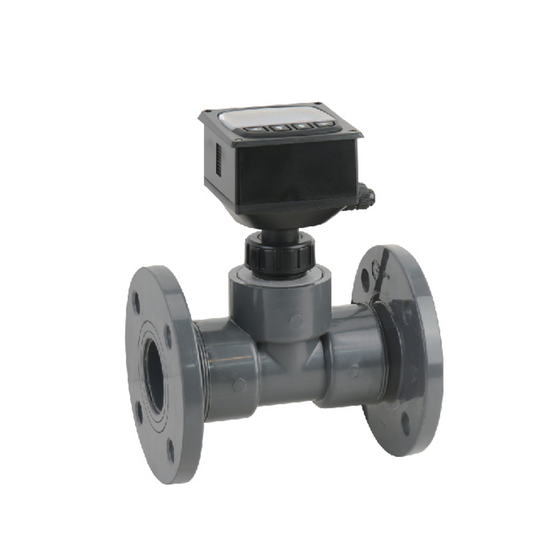
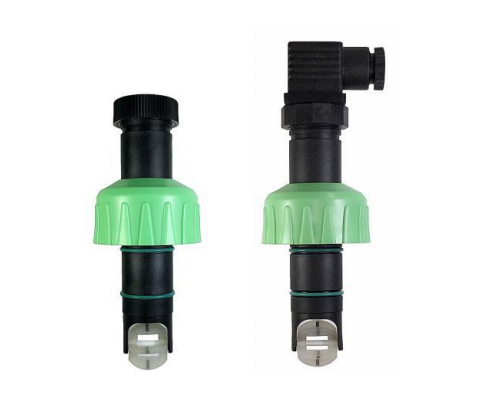
The KF510 Inline Impeller Flow Sensor is commonly used for liquid flow measurement in industries such as water, petroleum, and chemicals, including water supply and drainage systems and hydraulic systems. It features a simple structure, easy installation, and wide application in industrial fields and laboratories. Its measurement principle is based on the fact that when fluid flows through the flow meter, it drives the impeller to rotate; the impeller’s rotational speed is positively correlated with the fluid velocity. The impeller drives a magnetoelectric device, converting the mechanical rotation into electrical pulse signals. By calculating the pulse frequency, the instantaneous or cumulative flow rate of the fluid is obtained.
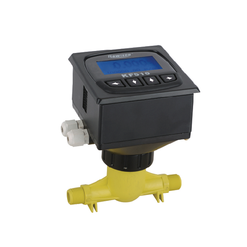
It comes in two connection styles, making it suitable for almost any line: KF510-FA with flange connections (DN32 to DN250) and KF510-VA with threaded connections (DN10 to DN50). Together, they cover DN10 through DN250.
The KF510 Inline Impeller Flow Sensor works by using a flow meter to rotate an impeller as fluid flows through it. The impeller’s rotation speed is directly proportional to the fluid velocity. The impeller drives a magnetoelectric device, which converts the mechanical rotation into electrical pulse signals. By calculating the pulse frequency, the instantaneous or cumulative flow rate of the fluid can be determined.
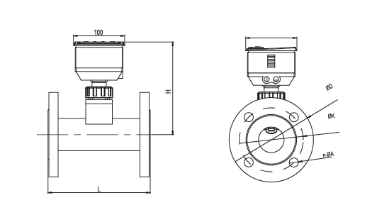
Dimensions per manufacturer datasheet: L = face-to-face length, D = flange outer diameter, K = bolt-circle diameter, H = height. N-Φd = number of bolt holes × bolt-hole diameter (e.g. 4-Φ18 = 4 holes of Ø18 mm).
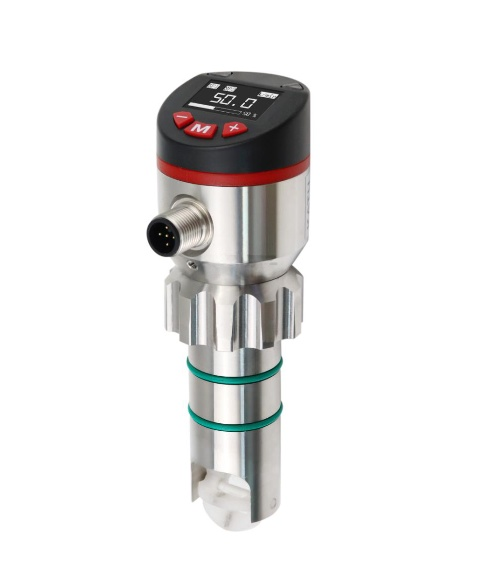
Threaded Model Selection – KF510-VA (DN10-DN50)
Code
Bore
External thread
Flow range (m³/h)
Working pressure
A (mm)
B (mm)
10
DN10
G3/8″
0.1 – 1.8
1.0 MPa
152
121
15
DN15
G1/2″
0.2 – 4
1.0 MPa
152
130
20
DN20
G3/4″
0.3 – 6
1.0 MPa
158
134
25
DN25
G1″
0.5 – 12
0.8 MPa
158
141
40
DN40
G1-1/2″
2 – 24
0.8 MPa
168
175
50
DN50
G2″
4 – 40
0.8 MPa
184
175
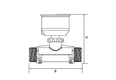
A and B are overall dimensions as listed in the manufacturer datasheet.
Application Industries
The KF510 measures liquid flow across a wide range of industries:
Petrochemical Industry
Metallurgical Industry
Textile Industry
Pharmaceutical Industry
Semiconductor Industry
Food and Beverage Industry
Paper and Pulp Industry
Power Plants
Urban Water Supply and Drainage
Environmental Protection
New Energy Industry
Shipbuilding Industry
Order Guide
Order code structure (8 fields): Series – Installation – Bore – Connection – Function – Power – Alarm – Unit
Connection codes follow the order listed in the manufacturer datasheet. Confirm flange standard (GB / ANSI / JIS) and rating with the supplier when ordering.
Among the several types of flow meters available in the market, helical flow meters attract attention due to their precision and ability to handle high-viscosity fluids and challenging flow conditions. Helical flow meters are extremely accurate measuring instruments to determine the volume flow rate of liquids in closed pipelines. This article explores the working principles, … Read more
In practice, most machines involve rotary motion as well as linear motion. Rotary motion is defined by stable operation and low impact on mechanical equipment. Therefore, it is very important for the smooth operation of the instrument. Rotary flow meters have been in use for a long time. Over time, they have become the preferred … Read more
Sino-Inst supplies various types of fertilizer flow meters, including volumetric flow meters, mass flow meters, and mass flow meters for powdered fertilizers. These are suitable not only for agricultural irrigation management but also for industrial-grade production monitoring and management. Fertilizer use has steadily increased over the past 50 years, especially in high-value crops such as … Read more
A method by which we can measure the amount of heat involved in a chemical or physical process is known as Calorimetry. Calorimetry is used to measure the amount of heat transferred into or from a substance. Among the several types of flow meters available, the calorimetric flow meter stands out for its reliability, preciseness, … Read more
Paint flow meters are necessary component of various industrial environments to measure and control the flow of paint, adhesives, and coatings. In applications like automotive, industrial manufacturing or commercial painting demand metering competent of handling thick, “sticky” and often abrasive materials. Additionally, Paint flow meters must be able to resist pump pulsations at often high line pressures due to the … Read more
Chlorine is an extremely reactive element and a strong oxidizing agent. The gas is greenish yellow in color. It is easy to compress and can be liquefied into a clear amber coloured liquid. As a corrosive and aggressive gas, the flow measurement of chlorine is a difficult job. Aggressive chemical element bring an element of … Read more
The KF510 Inline Impeller Flow Sensor’s in-line design allows for direct installation in pipelines, resulting in more stable measurements. Custom options are available for both threaded and flanged connections. Please contact our sales engineers at any time to confirm flow measurement solutions.
Zhang Wei, possesses 20 years of experience as an automation instrumentation engineer, specializing in the research, design, installation, commissioning, and maintenance of automation instruments.
Face to various instrument communication protocols (such as Modbus, Profibus, etc.), with solid hardware circuit design and software programming skills (proficient in C language and PLC programming). Has extensive project experience; projects he has led and participated in have all achieved outstanding results, improving product accuracy, reducing costs, and increasing production efficiency.
Possesses excellent communication and coordination skills and a strong team spirit, enabling him to quickly respond to customer needs and provide high-quality automation instrumentation solutions.