
Torque Transducer vs Torque Sensor vs Torque Meter: What’s the Difference?
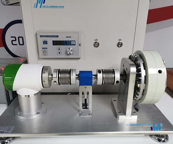
In most procurement communications and practical applications, we tend to use the terms “torque transducer,” “torque sensor,” and “torque meter” interchangeably. A torque transducer/sensor, torque cell, and torque meter all refer to a class of devices used to measure torque on various rotating or non-rotating mechanical components and convert it into a measurable electrical signal.
However, it is important to note that in the United States, the term “torque meter” refers to a handheld torque tester, not an in-line sensor installed within a drivetrain.
Of course, what truly determines your purchase decision is not these terms, but rather the measurement conditions—whether the component is rotating or not (reaction vs. rotary)—as well as the output signal and mounting interface.
Reaction and Rotary Torque Transducers
Our torque transducers grouped by how they are used: reaction sensors that do not rotate, rotary sensors for running shafts, and compact or special-mount models.
Reaction (static) torque sensors

CL1-98 Reaction Torque Sensor
Non-rotating sensor with flanges on both ends, for torque that turns less than 360°. Ranges up to 100,000 Nm (larger on request). Output 4-20 mA, 1-5 V or 5-15 kHz.
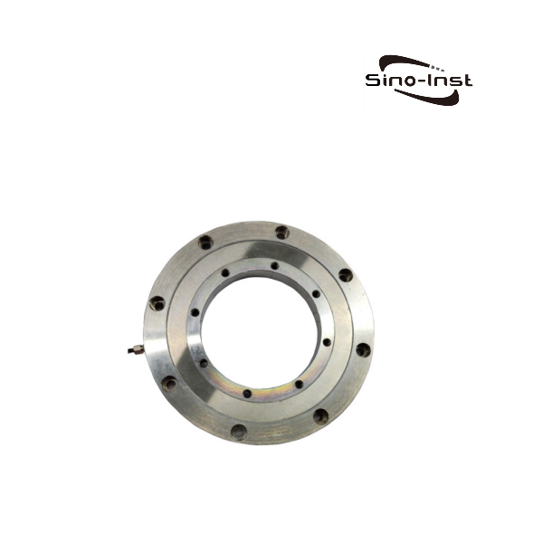
CL1-9500 Disc Reaction Torque Sensor
Stainless steel disc with flanges on both faces and a short axial length. 50 to 1,000 Nm, 1.5 mV/V output, ±0.1% or ±0.2% F.S.
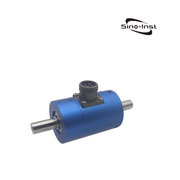
CL1-12 Shaft-to-Shaft Reaction Sensor
Low-range static sensor from 0.1 to 5 Nm with shafts on both ends, for small valves, mixers and torque testing machines. mV/V bridge output.
Rotary (dynamic) torque sensors

CL1-803 Contactless Rotary Torque Sensor
Rotary sensor with keyed shafts and no slip rings, for motor and engine test benches. Up to 8,000 rpm with a 60 pulse/rev speed signal. Torque output 5-15 kHz (10 kHz zero), 4-20 mA, 0-5 V or 0-10 V.

CL1-106 Bearingless Flange Torque Sensor
Flange disc design with no bearings, so no bearing friction in the reading. 50 Nm to 10 kNm, speeds up to 30,000 rpm. Output 10±5 kHz, ±5/±10 V, 4-12-20 mA, RS485 or CAN.
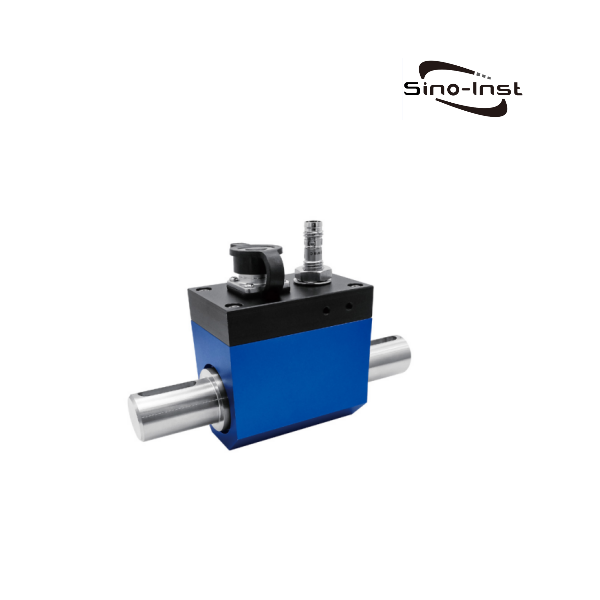
CL1-206 Torque Transducer with Speed
Inline rotary transducer from 5 to 5,000 Nm with a built-in speed measurement up to 1,000 rpm. Reads torque in both directions. 1.0-1.5 mV/V output.
Compact and special-mount models
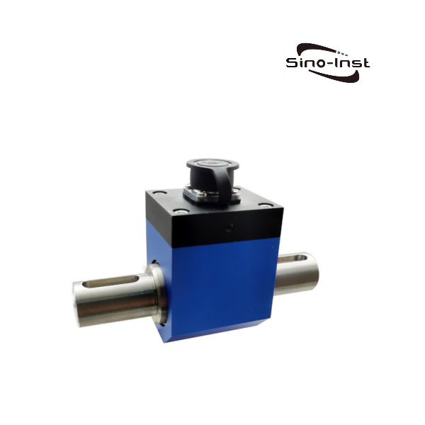
CL1-204 Inline Torque Transducer
Compact inline transducer from 5 to 2,000 Nm with a 1.0-2.0 mV/V bridge output for an external amplifier or indicator. Reads torque in both directions; 5-500 Nm models run up to 1,800 rpm.
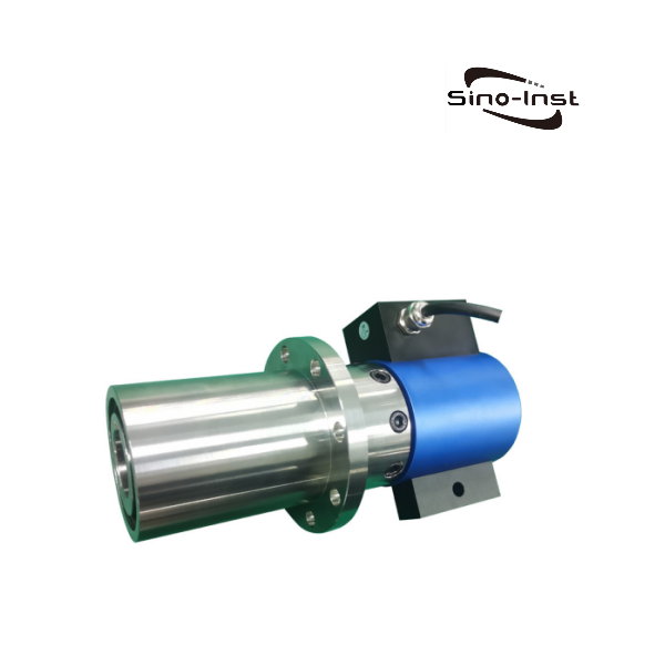
CL1-107 Pulley Rotary Torque Transducer
Mounts on a belt drive through a pulley instead of an inline coupling. 0 to 100 Nm, up to 6,000 rpm, with speed output. Output 10±5 kHz, 0-10 V, 4-20 mA, RS485 and more.
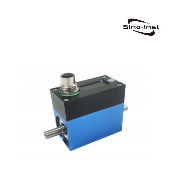
CL1-104 High-Speed Rotary Torque Sensor
Small-range shaft sensor from 0.1 to 5 Nm for speeds up to 16,000 rpm, such as small motors and spindles. Optional speed output. Output 10±5 kHz, ±5/±10 V, 4-12-20 mA, RS485 or CAN.
What Is a Torque Transducer?
A torque transducer is a precision measuring device that converts mechanical torque into a measurable electrical signal. It is used to detect the magnitude and changes in torque on rotating or non-rotating components.
It takes mechanical physical quantities as input and produces electrical or digital signals as output. Capable of simultaneously measuring parameters such as torque, rotational speed, and power, it serves as a critical interface component connecting mechanical systems to electronic control systems.
A key feature of torque transducers is their operation on a 12–28 VDC power supply, with output signals including: 0–5 VDC, 0–10 VDC, ±10 VDC, ±5 VDC, 0–20 mA, 4–20 mA, 10 ±10 mA, 12 ±8 mA, and RS485, among others.
Sino-Inst’s torque transducers operate on the principle of resistive strain gauges. Resistive strain gauges are bonded to the surface of the elastic shaft at specific angles to form a Wheatstone bridge configuration. When the elastic shaft undergoes minute deformation due to torque, it causes a change in the bridge’s resistance. This change in resistance is converted into a corresponding change in the electrical signal, thereby enabling torque measurement.
The sensor consists of a torsion shaft, a measuring bridge, an instrumentation amplifier, and an interface circuit. The torsion shaft serves as the sensing element, generating maximum compressive and tensile stresses at 45° and 135°, respectively; at these angles, the principal stresses and shear stresses are equal.
The measuring bridge employs semiconductor resistive strain gages connected in a differential full-bridge configuration, with its output voltage being proportional to the torque applied to the torsion shaft.
The amplification circuit uses an instrumentation amplifier, which can be either a dedicated instrument amplifier or a combination of three operational amplifiers. To ensure high accuracy, the sensitivity coefficient must be kept constant.
Torque Transducer vs Torque Sensor
Simply put, a torque transducer is a complete device that converts torque into an electrical signal. A torque sensor is the strain gauge that detects torque.
A sensor is a sensitive element—the part that directly “detects” torque. In a torque sensor, this is the strain gauge attached to the elastic shaft. When the shaft is subjected to torque and undergoes minute deformation, the resistance of the strain gauge changes accordingly. It is responsible only for detection and does not itself output a signal that can be used directly.
A transducer—also known as a converter—is the complete device that converts torque into an electrical signal for output. It includes an elastic shaft, strain gauges, a Wheatstone bridge, a housing, and wiring; rotary types may also include slip rings or non-contact transmission mechanisms. When powered (excited), it outputs a voltage signal proportional to the torque, typically measured in millivolts per volt (mV/V).
Of course, most of the time we do not strictly distinguish between these two terms. What really needs to be confirmed is the output signal (mV/V or amplified) and whether it is rotational (rotary) or non-rotational (reaction).
What is a Torque Meter?
Torque meter sometimes refers to handheld torque testers used with wrenches and screwdrivers, and other times it refers to inline rotary torque sensors. These are completely different products. Therefore, when searching for a torque meter, it is essential to clearly define your application scenario and measurement requirements.
Handheld torque testers are primarily used to calibrate torque wrenches, electric screwdrivers, and bottle cap torque, among other applications. They do not need to be mounted on a drive shaft. They typically measure the peak torque at the moment of tightening.
Inline torque meters are primarily used to measure the operating torque of motors, pumps, gearboxes, and marine shafts. They must be mounted on the drive shaft and connected to both ends via couplings. They can measure continuous torque, rotational speed, and power.
To accurately identify the product you need, there are two key factors to consider. First, whether the sensor rotates with the shaft; second, what type of signal output is required. Let’s take a closer look.
Reaction vs. Rotary
Whether the sensor rotates with the shaft is far more important than whether it is referred to as a “sensor” or a “transducer.”
A reaction torque sensor does not rotate. It is mounted between a fixed base and the part being twisted and measures the torque that reacts back into the mounting, for example on a torque wrench calibration bench, a valve actuator test stand or a locked-rotor motor test. With no rotating body it needs no slip ring, so it costs less.
A rotary torque sensor sits inline in the drive shaft and turns with it, connected through couplings. It measures torque while the shaft runs, for example on a motor or gearbox test bench, and usually adds a speed signal so power can be calculated. The signal crosses the rotating gap through slip rings or contactless transmission, so rotary models cost more and have a maximum rated speed.
Output Signals
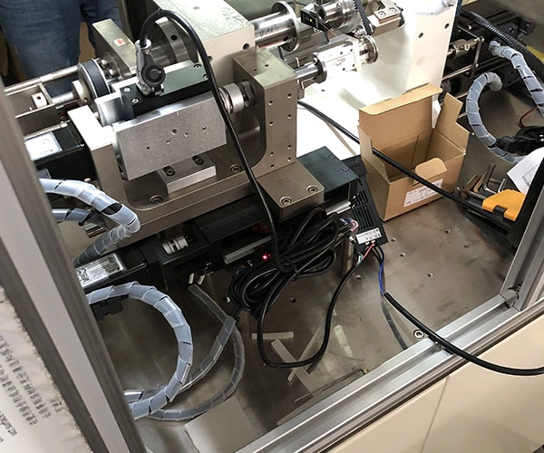
Most Sino-Inst industrial torque sensors have built-in signal conditioning, so the output is a frequency, voltage, current or digital signal that a PLC, data logger or display can read directly. Compact models such as the CL1-204 and CL1-206 output the raw bridge signal (about 1–2 mV/V) and need an external amplifier or indicator.
| Output Type | Options Available | Zero Torque / Notes | Best For |
|---|---|---|---|
| Frequency | 10 ± 5 kHz (5 V square wave) | 10 kHz = zero torque; 15 kHz and 5 kHz = full scale in opposite directions | Rotating test benches, long cable runs, sites with VFD noise; pulse counting resists interference |
| Bipolar voltage | 0 to ±5 VDC, 0 to ±10 VDC | 0 V = zero torque; sign indicates direction | DAQ cards and oscilloscopes where CW/CCW must be distinguished |
| Offset voltage | 0-5-10 VDC | 5 V = zero torque | PLCs that only accept unipolar voltage but still need direction |
| Unipolar voltage | 0-5 V, 0-10 V | 0 V = zero torque (one direction only) | Applications where torque acts in one direction only |
| Current | 4-12-20 mA, 4-20 mA, 0-20 mA | 4-12-20 mA: 12 mA = zero torque | Long-distance transmission to PLC/DCS in electrically noisy plants |
| Digital | RS485, RS232, CAN | Direct digital reading; torque, speed and power available | Multi-sensor networks, PC software, vehicle CAN bus |
If you need to measure bidirectional torque—such as a motor rotating in both directions or a valve opening and closing—you must select an output with zero-point offset. This includes options such as 10±5 kHz, 0–5–10 V, 4–12–20 mA, or ±5/±10 V. If you select a unidirectional 0–10 V or 4–20 mA output, the signal will drop directly to 0 during a direction change—this is the most common oversight when requesting a quote. For applications involving long cables and variable-frequency motors, prioritize the frequency-based or 4–12–20 mA outputs.
Order Guide
Therefore, based on the information provided above, the specific product name you choose is not the most important factor. You can simply compile the following points and contact us to confirm the product:
- Rated range and overload (peak/shock)
- Static or rotating; maximum rotational speed
- Connection method (shaft-to-shaft with key, flange, square drive, pulley)
- Signal output and power supply requirements
- Whether speed, angle, or power is required
- Accuracy (total error %FS)
- Environment (temperature, IP rating, explosion-proof)
- Calibration certificate requirements.
Further Reading
- What Is a Torque Sensor? and Types
- How to Measure Torque?
- Motor Torque Measurement – Static and Dynamic Sensors
FAQ
Zhang Wei, possesses 20 years of experience as an automation instrumentation engineer, specializing in the research, design, installation, commissioning, and maintenance of automation instruments.
Face to various instrument communication protocols (such as Modbus, Profibus, etc.), with solid hardware circuit design and software programming skills (proficient in C language and PLC programming). Has extensive project experience; projects he has led and participated in have all achieved outstanding results, improving product accuracy, reducing costs, and increasing production efficiency.
Possesses excellent communication and coordination skills and a strong team spirit, enabling him to quickly respond to customer needs and provide high-quality automation instrumentation solutions.
Want to see more of our engineering guides in Google Search? Add Sino-Inst as a preferred source.